Note: Descriptions are shown in the official language in which they were submitted.
CA 02598807 2007-08-17
METHOD OF NORMALIZING SURFACE TENSION OF A SAMPLE FLUID
FIELD OF THE INVENTION
[0001] The invention relates to the field of clinical
analyzers, and more particularly to a novel method for
normalizing surface tension of a sample fluid being run on
a clinical analyzer.
BACKGROUND OF THE INVENTION
[0002] Clinical analyzers generally utilize dry
chemistry systems and/or wet chemistry systems. Each
chemistry system is somewhat unique in terms of its
operation. For example, known "dry" chemistry systems
typically include a sample supply which includes a number
of sample containers, a metering/transport mechanism, and
an incubator having a plurality of test read stations. A
quantity of sample is aspirated into a metering tip using a
proboscis or probe carried by a movable metering truck
along a transport rail. A quantity of sample from the tip
is then metered (dispensed) onto a dry slide element which
is loaded into the incubator. The slide element is
incubated and optical or other reads are taken for analyte
detection.
[0003] A "wet" chemistry system on the other hand,
utilizes a reaction vessel such as a cuvette, into which
quantities of patient sample, at least one reagent fluid,
and/or other fluids are combined for conducting an assay.
The assay is also incubated and tests are conducted for
analyte detection. The "wet" chemistry system also
includes a metering mechanism to transport patient sample
fluid from the sample supply to the reaction vessel.
1
ak 02598807 2007-08-17
[0004] A number of known clinical analyzers incorporate
both wet and dry chemistry systems in a single apparatus,
and are known as "combinational" clinical analyzers.
[0005] When operating clinical analyzers, various
problems can be encountered. For example, the sample
volume that the analyzer delivers to the reaction cell may
vary by sample/patient. In addition, some analytes may
have reduced recovery and the recovery may vary by
sample/patient. Both of these issues result in what an end
user would observe as random bias. Customers usually
relate to this error as the lack of fit to a regression
line compared to a reference method. In addition, certain
controls and proficiency fluids may show lower predictions
on a particular analyzer compared to other systems.
[0006] A need exists for methods which can overcome
these problems and improve the accuracy and consistency of
clinical analyzers.
BRIEF SUMMARY OF THE INVENTION
[0007] To this end, investigation into the causes of
these problems shows that the random error in sample volume
is driven predominantly by the variability in the sample
fluid surface tensions. The random error in the recovery
is driven in part by the random error in volume but for
some assays there is also a loss in the analyte being
measured because the analyte tends to stick to the plastic
surfaces as the analyzer processes it.
[0008] The subject invention provides a method which
overcomes these problems by normalizing surface tension of
a sample fluid on a clinical analyzer. The method uses a
surface tension-reducing agent, which may also block
adhesion of analytes to plastic and which may also improve
2
ak 02598807 2014-05-08
metering performance of the clinical analyzer. The method
provided comprises:
aspirating a portion of a sample fluid into a
metering tip, the metering tip having a lower end through
which the sample fluid is aspirated and an upper end;
sealing the lower end of the metering tip, forming a
cuvette for the portion of the sample fluid;
pre-treating a micro-tip with a surface tension-
normalizing agent, and then dispensing the surface tension-
normalizing agent into the sample fluid in the cuvette;
mixing the surface tension-normalizing agent and the
sample fluid in the cuvette using the micro-tip to create a
mixture of the sample fluid and the surface tension-
normalizing agent, the mixture having a normalized surface
tension; and
using the mixture for testing on the clinical
analyzer.
[0008A] More specifically, in one embodiment there is
provided a method of normalizing surface tension of a sample
fluid on a clinical analyzer, the method comprising:
first aspirating a portion of the sample fluid into
a metering tip, the metering tip having a lower end through
which the sample fluid is aspirated and an upper end, and the
sample fluid being free of surface-tension normalizing agent;
then sealing the lower end of the metering tip,
forming a cuvette for the portion of the sample fluid;
then pre-treating a micro-tip with a surface
tension-normalizing agent by aspirating a volume of a surface-
tension normalizing agent into the micro-tip, then dispensing
out a portion of the volume of the surface-tension normalizing
3
ak 02598807 2014-05-08
agent and retaining in the micro-tip a remaining portion of
the volume of the surface-tension normalizing agent;
then dispensing the remaining portion of the volume
of the surface tension-normalizing agent into the sample fluid
in the cuvette;
then mixing the remaining portion of the volume of
the surface tension-normalizing agent and the sample fluid in
the cuvette using the micro-tip to create a mixture of the
sample fluid and the surface tension-normalizing agent,
wherein the mixing comprises repeatedly aspirating and
dispensing a volume of the mixture, the volume of the mixture
being less than or equal to the volume of the surface-tension
normalizing agent used to pre-treat the micro-tip, the mixture
having a normalized surface tension; and
using the mixture for testing on the clinical
analyzer.
[0009] The method of the subject invention overcomes the
above problems of prior analyzers, without adulterating the
original sample fluid and without substantially slowing down
the throughput of the analyzer. Additional features and
advantages of the subject invention will be apparent from the
description which follows when considered in conjunction with
the attached figures.
3a
CA 02598807 2007-08-17
BRIEF DESCRIPTION OF THE DRAWINGS
[0010] Fig. 1 is an operational block diagram of a
combinational wet/dry clinical analyzer including a
plurality of stations that interact with a metering system;
[0011] Fig. 2 is a top perspective view of the sample
aliquot handler of Fig. 1;
[0012] Fig. 3 is a partially exploded top perspective
view of the sample aliquot handler of Figs. 1 and 2;
[0013] Fig. 4 is a bottom view of the sample aliquot
handler of Figs. 1- 3;
[0014] Fig. 5 is a top plan view of the sample aliquot
handler of Figs. 1-4;
[0015] Fig. 6 is an exploded top perspective view of a
tip sealer used in connection with the sample aliquot
handler of Figs. 1-5;
[0016] Fig. 7 is a partial top perspective of the cover
of the sample aliquot handler of Figs. 1-6 showing an
exploded view of a tip stripper;
[0017] Fig. 8 is an enlarged partial top perspective
view of the sample aliquot handler of Figs. 1-7 showing the
removal of a sealed metering tip from the handler to a dump
station;
[0018] Figs. 9 and 10 are partial side elevational views
illustrating a sample integrity read station for the sample
aliquot handler of Figs. 1-8;
[0019] Fig. 11 is a perspective view of a metering
system for the analyzer of Fig. 1 showing a dispenser and a
carriage;
[0020] Fig. 12 is a perspective view of a pump for the
dispenser and a drive mechanism for the carriage
operatively connected to a control system for performing a
calibration and automatic alignment method; and
4
CD. 02598807 2007-08-17
[0021] Fig. 13 is a side elevational view of a pair of
disposable tips, a metering tip and a micro-tip, used in
conjunction with the chemical analyzer of Figs. 1-12.
DETAILED DESCRIPTION OF THE INVENTION
[0022] The following description relates to a
combinational (i.e., wet/dry) clinical analyzer that is
used for the testing of biological samples, such as urine,
whole blood, serum, or plasma, preferably human patient
samples. The invention is then described in the context of
this particular analyzer. It should be readily apparent to
those of ordinary skill in the art that the method of the
subject invention can also be practiced on analyzers of
other configurations that can readily be adapted to the
method disclosed herein. For example, the analyzer could
include a pair of wet chemistry systems or only a wet
chemistry system.
[0023] By "combinational" it is meant that the analyzer
includes at least two chemistry systems which can encompass
any combination of "dry" and/or "wet" chemistry systems.
In brief and in a typical "dry" chemistry system, a patient
sample and/or other fluids are aspirated from a fluid
supply and deposited onto a dry slide element such as those
described in U.S. Patent No. 3,992,158 to Przyblyowicz et
al. The dry slide element is incubated and the amount or
presence of at least one analyte in the sample metered onto
the element is determined, such as through use of an
electrometer, reflectometer or other suitable testing
device.
[0024] A "wet" chemistry system for purposes of the
description which follows includes a reaction vessel which
receives predetermined volumetric quantities of sample,
CA 02598807 2007-08-17
reagent, and other fluids which are appropriately metered
into the reaction vessel in order to perform an assay(s).
The assay is incubated as the fluids are added to the
assay(s) and specific analysis is performed, such as
through luminescence, light transmissivity, photon
detection, and the like using suitable testing apparatus.
[0025] Several other terms are used throughout the
discussion including the terms "metering tips" and "micro-
tips". For purposes of this description, a metering tip
refers to a fluid aspirating/dispensing member which can be
attached to a proboscis as used in a metering mechanism.
The tip includes an open top end and a bottom dispense end
and is capable of retaining a volumetric quantity of fluid.
Metering tips in and of themselves are well known in the
field. A "micro-tip" for purposes of this discussion
refers to a metering tip which fits the definitional
requirements set forth above. In addition, this tip is
sized to retain a smaller (micro) volume of fluid.
Moreover, the micro-tip can be fitted within the confines
of the metering tip for advantages which will be apparent
below.
[00261 Referring to Fig. 1, there is shown an automated
combinational clinical analyzer 10 having a number of
component systems which are briefly discussed to provide
adequate background for the invention. The analyzer 10
includes a primary sample handler 14 that retains a
plurality of primary sample containers 18, a primary
metering mechanism 22 which includes a metering transport
rail 26 and a metering truck 30 which is movable along the
transport rail between a number of stations. Among the
stations disposed along the travel path of the metering
mechanism 22 are a metering station 68 for a first
6
CD, 02598807 2007-08-17
incubator assembly 34. At the metering station 68, a
quantity of sample can be deposited onto a dry slide
element which is then shuttled into the incubator assembly
34. The incubator assembly 34 includes at least one read
station including a testing device for correlated analyte
detection, such as reflectometer (not shown) or an
electrometer (not shown). The preceding components each
comprise a dry chemistry system for the herein described
automated combinational analyzer 10.
[0027] Still referring to Fig. 1, the analyzer 10
further includes a secondary metering mechanism 42 that
includes a metering truck 44 which is also movable along
the metering transport rail 26, a reagent wheel 52 which
includes a plurality of containers of at least one reagent
fluid, a second incubator assembly 56, a micro-tip supply
58, and a reaction vessel conveyor 60 which carries a
plurality of reaction vessels 64. These components have
merely been listed in this portion of the discussion.
Details relating to their features will be additionally
supplied in a later portion of the discussion. For
purposes of this description, however, each of the above-
noted components define a wet chemistry system for the
herein described combinational analyzer 10.
[0028] As introduced above, the primary metering
mechanism 22 and the secondary metering mechanism 42 travel
among a number of stations of the analyzer 10. Each of
these stations is defined as a metering stopping point for
the metering truck 30 and 44 respectively. By way of
example, and in no paticular order of significance or
priority, these metering stopping points include for
example: a primary metering point (P1) for the initial
aspiration of sample by the primary metering mechanism 22;
7
ak 02598807 2007-08-17
a reflex metering point (P2) where additional aspirates of
sample can be taken if needed, i.e. for dilution purposes,
etc.; a priority handling or STAT metering point (P3) for
introducing priority/STAT samples; a thin film metering
point (P4) where the slide element 36 is spotted with
sample fluid; a tip seal point (P5) for sealing a lower end
105 of a metering tip 102 (see Fig. 10) at the tip sealer
142 for forming a cuvette ("cuvetip"); a first tip pick-up
point (P6) where the primary metering mechanism 22 obtains
a new metering tip 102; a first tip eject point (P7) where
the primary metering mechanism 22 drops off a used metering
tip 102 or sealed tip 102 after testing has been completed;
a second cuvette metering point (P8) where the secondary
metering mechanism 42 meters samples from a cuvetip; a
second tip pick-up point (P9) where the primary metering
mechanism 22 obtains another new metering tip 102; a
cuvette metering point (P10) where the secondary metering
system meters into a wet cuvette (traditional type); a
micro-tip pick-up point (P11) where the secondary metering
mechanism 42 picks up new microtips 107; a second tip eject
point (P12) where the secondary metering mechanism 42
deposits used microtips; and a wet reagent metering point
(P13) where the secondary metering mechanism 42 aspirates
wet reagent at the reagent wheel 52.
[0029] As will be described in greater detail later in
the disclosure, these stations or points (Pl-P13) are
illustrative of the various points interacted on by the
metering mechanisms 22 and 42 respectively.
[0030] Still referring to Fig. 1, a sample aliquot
handler apparatus 40 is disposed in spaced relation between
the first incubator assembly 34 of the dry chemistry system
and the second incubator assembly 56 of the wet chemistry
8
CD, 02598807 2007-08-17
system of the above-described analyzer 10. The following
discussion pertains to a specific description of the sample
aliquot handler 40 followed by the operational details of
the sample handler in conjunction with the wet and dry
chemistry systems of the herein described combinational
analyzer 10.
[0031] First, and as shown in Figs. 1-3 and 5, the
sample aliquot handler 40 includes a circular cylindrical
housing 80 having a cover 84. The housing is defined by an
interior sized for containing a number of retained
components which include an inner rotor assembly 88 (not
shown in Fig. 2), a pair of position sensors 126, 128, and
a tip removing assembly 122. Each of the above-noted
components are attached to an interior facing surface of a
bottom mounting plate 138 of the housing 80. In addition,
an outer rotor assembly 92 is supported at the top of the
housing 80, the outer rotor assembly being disposed outside
the periphery of the cover 84.
[0032] A pair of stanchions 90 also extending from the
interior facing surface of the mounting plate 138 assist in
supporting the cover 84 which covers the inner rotor
assembly 88. The cover 84 further includes a center handle
86, as well as a pair of opposing twist fasteners 87 which
engage corresponding openings provided in the stanchions
90. The cover 84 also includes a tip stripping assembly
154 that is described in greater detail below. The
following relates to a more detailed discussion of the
inner and outer rotor assemblies 88, 92. Referring to Figs.
3, 5, and 8, the inner rotor assembly 88 includes a
rotatable circular ring member 96, which is rotatably
driven about a center axis of rotation by means of a gear
drive mechanism. The drive mechanism includes a motor
9
CD, 02598807 2007-08-17
having a rotating engagement portion 130 which extends
above the interior facing surface of the mounting plate
138. A set of linear gear teeth 134 are provided on an
inner edge of the ring member 96 which mesh with the
engagement portion 130. The ring member 96 of the inner
rotor assembly 88 further includes a plurality of sample
container supply stations 100, each of the stations being
circumferentially disposed about the periphery of the ring
member. Each of the sample container supply stations 100
are defined by a slotted outer opening 104 which is linked
to a radially adjacent and contiguous inner opening 108.
The size of the inner opening 108 is much larger than that
of the slotted outer opening 104 for reasons which will be
become apparent below. According to this specific
embodiment, (30) thirty sample container supply stations
100 are provided on the inner ring member 96, though it
should be readily apparent that this parameter can be
easily varied.
[0033] Referring now to Figs. 2, 3, 5, and 8, and as
noted above, the outer rotor assembly 92 of the sample
aliquot handler 40 extends outside the periphery of the
cover 84. This assembly is comprised of a circular support
ring 114 having a plurality of circular circumferentially
disposed tip supply stations 118 which are equally spaced
about the periphery of the ring. Like the inner rotor
assembly 88, a gear drive mechanism is used to rotatably
drive the ring. A set of linear gear teeth 146 provided on
an outer edge of the support ring 114 are engaged by the
engagement portion (not shown) of a motor (not shown) to
cause rotation of the support ring 114. It should be
pointed out that the above described gear drive mechanisms
are exemplary. That is, other drive mechanisms can be
CA 02598807 2007-08-17
employed to cause rotational movement of either the support
ring 114 or the ring member 96.
[0034] The support ring 114 and the ring member 96 of
the outer rotor assembly 92 and inner rotor assembly 88,
respectively, are concentric, the rotating components of
each assembly being independently driven by their
respective gear drive mechanisms about a common axis of
rotation.
[0035] According to this embodiment, the support ring
114 of the outer rotor assembly 92 further includes a
series of circumferentially spaced slots 120, Fig. 8,
disposed on an outer periphery of the ring for aiding in
the initial angular positioning of the ring during
assembly.
[0036] Still referring to Figs. 2, 3, 5 and 8, each of
the tip supply stations 118 of the support ring 114 of the
outer rotor assembly 92 are circular openings which are
sized to receive a metering tip 102, Fig. 9, 10, from a tip
supply (not shown) at a tip deposit station 150 provided as
an opening in an adjacent cover 166 covering the drive
motor (not shown) for the rotatable support ring 114 of the
outer rotor assembly 92. According to this embodiment, a
total of sixty (60) equally spaced tip supply stations 118
are provided, though it should be apparent, as previously
noted above, that this parameter can be suitably varied.
[0037] According to this specific embodiment, each of
the sample container supply stations 100 and the tip supply
stations 118 of the inner rotor and outer rotor assemblies
88, 92, respectively, are sized to receive a fluid
aspirating/dispensing member. According to this
embodiment, the fluid aspirating/dispensing member is a
metering tip 102, shown in Figs. 9 and 10, which includes
11
CA 02598807 2007-08-17
an open upper end 103 and a lower dispense end 105 through
which liquid can be dispensed. More specifically, the
metering tip described herein is a disposable plastic
member made from polypropylene or other plastic moldable
material, such as the metering tip manufactured by the
Johnson & Johnson Company under the trade name of VitrosTM,
though it will be apparent that other fluid
dispensing/aspirating members can be substituted.
[0038] Referring to Figs. 2-6, the sample aliquot
handler 40 includes a tip sealer 142 which is mounted by
conventional means, such as threaded fasteners, to the
exterior of the housing 80.
[0039] Referring more particularly to Fig. 6, the tip
sealer 142 includes a housing 170 which is mounted to the
exterior of the handler housing 80, Fig. 3, the housing
having a defined interior 174 and a cover 178 which covers
the top end of the housing held in place by fastener 202.
A number of components are contained within the sealer
housing 170 including a cylindrical support 194, and a
heating element assembly 190, which is placed in a recess
of the support within a bottom portion of an anvil 186.
The heating element assembly 190 includes a resistive type
heater and a control thermistor. The cover 178 includes a
center opening 182 which is sized to permit passage of a
metering tip 102, Fig. 9, such that the opening of the
dispense end 105 of the tip can be sealed through
engagement with the heated anvil 186. A safety thermostat
198 attached to the bottom of the housing 170 automatically
shuts down the tip sealer 142 if a predetermined
temperature is reached to prevent overheating. Further
details relating to the sealing of metering tips in this
manner is described in commonly owned U.S. Patent No.
12
CA 02598807 2014-05-08
6,797,518, issued September 28, 2004, of Jacobs et al.,
entitled ANALYSIS METHOD WITH SAMPLE QUALITY MEASUREMENT.
[0040] Referring to Fig. 7, the sample aliquot handler
40 further includes a tip stripping assembly 154 that is
provided within a recessed portion 210 of the bottom of the
cover 84, A pair of V-blocks 214 are biasedly maintained
in a first or "home" position by a pair of compression
springs 218 within respective slotted regions 215. The V-
blocks 214 are biased in order to create a predetermined
gap between a pair of tapered surfaces 220. The cover 84
includes an opening 162 within a raised portion 206, which
is aligned with the gap of the V-blocks 214 to permit
passage there through of a metering tip 102, Fig. 9. A
retaining plate 222 used to support the components of the
tip stripping assembly 154 is secured to the bottom of the
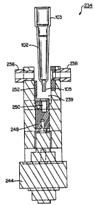
cover 84 using fasteners 226 (only one being shown in Fig.
7) which extend through corresponding holes 232 formed in
the retaining plate. Hole 230 permits the metering tip 102
to be dropped into an empty sample container supply
position 100 of the circular ring 96 of the inner rotor
assembly 88.
[0041] Referring to Figs. 9 and 10, a sample integrity
read station 234 includes a station housing 240 and an
optical reading device, such as a spectrophotometer which
includes receiving and transmitting optics 236, 238
disposed on opposite sides of a test slot or cavity 239. A
linear actuator 244 is disposed at the bottom of the
station housing 240, the actuator having an engagement
member 248 attached thereto which is vertically movable and
includes a tip receiving cavity 250 and a vertically
13
ak 02598807 2007-08-17
extending flag 252. The actuator 244 and engagement member
248 together form a lift mechanism that aligns the fluid
contents of a retained metering tip 102 with the receiving
and transmitting optics 236, 238 of the spectrophotometer.
The housing 240 of the sample integrity read station 234 is
stationarily positioned to the mounting plate 138 beneath a
predetermined angular position of the circular ring 96 and
the cavity 239 is aligned with the sample container supply
stations 100, Fig. 5. As described below, the sample
integrity read station 234 provides spectrophotometric
analysis of the sample contents of a sealed metering tip
102 in order to ascertain the presence of certain sera
components, such as hemoglobin, albumin, lipoproteins etc.
[0042] Referring to Fig. 1, and with respect to the
remaining components of the present analyzer 10, the second
incubator assembly 56 is positioned adjacent to the sample
aliquot handler apparatus 40. The second incubator
assembly 56 is sized to receive at least one reaction
vessel 64 and includes a read station (not shown) including
a testing device, such as a spectrophotometer, for
detecting the presence or amount of an analyte in a sample.
[0043] Each reaction vessel 64 is conveyed in relation
to the second incubator assembly 56 and a metering station
for receiving sample from sealed metering tips 102 within
the sample aliquot handler apparatus 40 and at least one
reagent from the reagent wheel 52.
[0044] The micro-tip supply 58 conveys a plurality of
disposable plastic micro-tips 107, Fig. 13, in which each
of the tips are smaller than the sealed sample-containing
metering tips 102, that are retained within the sample
aliquot handler apparatus 40, as shown in Figs. 2 and 3.
The micro-tips 107 are retained in packages which are
14
CA 02598807 2014-05-08
conveyed to a pickup station which is aligned with the
metering truck 44 of the wet chemistry system of the herein
described analyzer 10.
[0045] Each of the reaction vessels 64 includes a
plurality of spaced reaction chambers for conducting a wet
assay. A preferred version is described in commonly owned
U.S. Patent Pub. No. US 2003/0003591 of LaCourt et al.
entitled "Reaction Vessel",
The reaction chambers
can be provided for single (disposable) as well as for
multiple use, according to the present invention. The
vessels 64 of the present embodiment further include
windows (not shown) on opposing sides of each reaction
chamber which permit testing of the contents by means of a
testing device, such as a spectrophotometer (not shown)
which is included in a testing chamber which is disposed
adjacent to the second incubator assembly 56. It will
apparent, however, that other forms of reaction containment
devices, such as reaction wells, cuvettes, test tubes, and
even thin film or dry slide elements can be substituted.
[0046] The rotatable reagent wheel 52 includes a
plurality of reagent containers or packs 54 each being
disposed within appropriately sized slotted portions of a
rotatable ring component. Each of the reagent packs 54
contain at least one and preferably two separately housed
reagents within an injection molded structure, the packs
being driven by a suitable drive mechanism along a circular
path wherein the packs are stored for access and rotated to
an appropriate position for aspiration. The reagent packs
54 can be loaded individually through a slot (not shown) in
a cover (not shown) of the reagent wheel, the wheel further
CA 02598807 2007-08-17
including a cooler (not shown) which maintains the reagents
at an appropriate temperature and humidity.
[0047] As will now be more clearly described, the above-
described sample aliquot handler 40 is used to
asynchronously link the dry chemistry and wet chemistry
systems of the combinational clinical analyzer 10. Having
completed the description of the individual features and
subassemblies of the clinical analyzer 10, details relating
to the operation of the clinical analyzer are now provided.
[0048] Initially, a plurality of unsealed metering tips
102 are loaded one at a time as fed from a tip supply (not
shown) through the opening that defines the tip deposit
station 150 and are dropped into empty tip supply stations
118 provided on the support ring 114 of the outer rotor
assembly 92. The support ring 114 is rotated incrementally
by means of the gear drive mechanism (not shown) in order
to align empty tip supply stations 118 into proper
alignment with the tip deposit station 150.
[0049] As previously noted, the primary sample handler
14 contains a plurality of patient sample containers 18
which are movably disposed on rotatable sample trays 16.
Details relating to the primary sample handler 14 and
movement of the sample containers 18 are commonly known to
those of ordinary skill in the field and do not form an
essential part of the invention. Briefly, the sample
containers 18 are generally tubular in shape and are
disposed on rotatable sample trays 16 disposed on a drive
belt or other support. The sample trays 16 are typically
carousels which retain a plurality of the tubular sample
containers 18, the trays being incremented about an
elliptically shaped track by means of a drive mechanism
16
CA 02598807 2014-05-08
(not shown) such as a magnetic drive, belt, or other known
means into alignment with the metering transport rail 26.
[0050] As noted above, the metering transport rail 26 is
aligned with the primary sample handler 14 and the
auxiliary sample handler 40 such that a metering tip 102,
Fig. 9, can be attached onto a proboscis (not shown) of the
movable metering truck 30 of the primary metering mechanism
22 from a predetermined tip supply station 118.
[0051] The metering truck 30 is then shuttled along the
transport rail 26 to the primary sample handler 14 and a
volume of sample is drawn under vacuum and is aspirated
from one of the patient sample containers 18 into the
metering tip 102, Figs. 9 and 10. Specific details
relating to the attachment of a metering tip to a proboscis
as well as details relating to the aspiration and metering
of sample and other fluids are commonly known to those in
the field. An example is provided, for example, in U.S.
Patent No. 4,340,390 to Collins et al.
[0052] With reference to Fig. 11, metering truck 30, 44
comprises a dispenser 340 and a means for positioning
dispenser 340 which includes a carriage 342 for moving
dispenser 340 laterally through a plurality of stations (P1
through P13 as shown in Fig. 1) in analyzer 10, and a
vertical drive 344 for raising and lowering dispenser 340
at each of the stations P1 through P13. Dispenser 340
comprises a dispenser head 346 which is adapted to receive
disposable metering tip 102, and is connected by means of a
line 350 to a pump 352 (Fig. 12) of the positive
displacement type. Pump 352 comprises a piston, not shown,
which is driven by a bi-directional stepper motor 354. The
17
CD, 02598807 2007-08-17
stepper motor 354 is operatively connected to and
controlled by a control system 410.
[0053] When motor 354 is actuated by the control system
410 in one direction, a partial vacuum is created in line
350 by pump 352, and fluid is drawn into tip 102 until the
tip is partially filled. Motor 354 is actuated in an
opposite direction to meter fluid from tip 102. In the
metering operation, motor 354 drives pump 352 for a pre-
selected period during which the pressure in line 350 and
tip 102 is raised sufficiently to force about 10 ul of
fluid onto an analysis slide. Under certain operating
conditions, depending on the amount of fluid aspirated into
tip 102, it may be desirable to vent line 350 before
dispensing fluid onto an analysis slide. A pressure
transducer 356 is operatively connected to and controlled
by control system 410 and closely monitors pressure in line
350 for purposes which will be explained in more detail
hereinafter.
[0054] Carriage 342 is mounted for horizontal movement
on metering transport rail 26. Rail 26 is carried on a
pylon 343 attached to the analyzer frame, not shown. A
drive means for carriage 342 includes a bi-directional
stepper motor 372 (Fig. 12) which is connected to a capstan
drive 374. Drive 374 comprises a drum 376; a cable 378
carried on drum 376 is supported on guide pulleys 380 and
connected to carriage 342. The stepper motor 372 is
operatively connected to and controlled by the controller
410. It will be seen from Figs. 11 and 12, that when motor
372 is driven, for example, in a counterclockwise
direction, as viewed in Fig. 12, carriage 342 will move to
the right (Fig. 11). Carriage 342 must be located along a
line at multiple points or stations which include for
18
CD, 02598807 2007-08-17
example, stations at positions P1 through P13. Horizontal-
position sensors 386 of a photoelectric type cooperate with
a carriage flag 387 on carriage 342 to precisely position
the carriage 342 at each of these stations P1 through P13.
[0055] Vertical drive 344 comprises a rack 390 which is
attached to dispenser head 346. Rack 390 is raised and
lowered by means of a pinion 392 driven by a stepper motor
394 mounted on a carriage 342. Vertical-position sensors
396 cooperate with a rack flag 398 on rack 390 to precisely
determine the vertical position of dispenser head 346.
Power from a power supply, not shown, is supplied to the
sensors 396 and motor 394 through a ribbon cable 400. The
sensors 396 and motor 394 are operatively connected to and
controlled by the controller 410 through the ribbon cable
400.
[0056] In the use of the disclosed metering mechanism 22
and 42 with the high-throughput clinical analyzer 10, as
shown in Fig. 1, a metering operation takes place
approximately every nine (9) seconds. Thus, it will be
seen that each of the steps in the metering cycle must be
carefully controlled and monitored by the control system
410, and metering apparatus 30 and 44 must function in
timed relation to other elements of analyzer 10. Pressure
transducer 356 is used to monitor the performance of
apparatus 30 and 44. Pressure is sensed in line 350, and
if conditions are present such as a plugged tip 102, no
fluid in sample container 18, or a separation of the fluid
stream between the tip 102 and the slide element 36, or if
the tip 102 is close to a surface, they will be detected by
the pressure transducer 356. The control system 410 for
the metering apparatus 30 and 44 includes one or more
computers which may take any of the various forms known in
19
CA 02598807 2007-08-17
the art that include programmable microcomputers. In
general, the instructions and method of programming such
computers is well known in the art, and thus, no further
explanation is considered necessary.
[0057] The metering truck 30 carrying the unsealed
metering tip 102 with aspirated sample is shuttled along
the transport rail 26 from the primary sample handler 14 to
the metering station 68. At the metering station 68, a
volumetric portion of patient sample contained within the
metering tip 102 is dispensed onto a dry slide element,
shown pictorially as 36 in Fig. 1, which is arranged to be
loaded using conventional means, such as a reciprocating
pusher blade 39, also shown pictorially in Fig. 1, into the
first incubator assembly 34. The sample which is metered
is then used in conjunction with the dry chemistry system
of the herein described combinational analyzer 10. The
sample is metered onto, for example, a colorimetric or
potentiometric slide element which is incubated, the sample
being analyzed at a read station for correlated analyte
detection. Details relating to the incubation and testing
of dry slide elements is known in the field such as
described, for example, in U.S. Patent No. 4,296,069
entitled: Apparatus for Processing an Analysis Slide, and
therefore require no further discussion.
[0058] Following the above-described metering step, the
metering tip 102 is then further shuttled by the metering
truck 30 toward the sample aliquot handler 40 and more
specifically to the tip sealer 142. At the tip sealer 142,
the metering tip 102 is placed within the opening 182 of
the sealer housing 174 and is lowered until the tip is
positioned relative to the anvil 186. Heat from the
heating element 190 is applied through the anvil 186 to the
CA 02598807 2014-05-08
dispense end 105 of the tip 102 while the tip is still
attached to the proboscis (not shown) of the metering truck
30. The fluid within the tip 102 is aspirated further away
from the dispense end 105 and a bubble is formed which
prevents temperature effects to the fluid as well as
removing the fluid from the area to be sealed. As noted
above, further details relating to the above noted sealing
operation are provided in commonly
owned U.S. Patent No. 6,797,518, issued September 28, 2004,
of Jacobs et al., entitled ANALYSIS METHOD WITH SAMPLE
QUALITY MEASUREMENT.
[0059] The above sealing operation seals the dispense
end 105 of the metering tip 102, Fig. 9, 10, and therefore
creates a sample supply container for use by the wet
chemistry system of the present combinational analyzer 10
as will be described below.
[0060] Following the above sealing steps, the proboscis
(not shown) is raised in a conventional manner, removing
the metering tip 102 from the tip sealer 142. The metering
tip 102 is then shuttled along the transport rail 26 by the
metering truck 30 to the tip stripping assembly 154 which
is provided on the cover 84 of the sample aliquot handler
40. The opening 162 of the tip stripping assembly 154 is
aligned with the transport rail 26 and more specifically
the travel path of the metering truck 30. The proboscis
(not shown) is lowered along with the attached metering tip
102, Fig. 9, into the opening 162 of the raised portion 206
of the cover 84. Initially, the dispense end 105 of the
sealed metering tip 102, Fig. 9, 10, engages the ramped
surfaces 220 of the V-blocks 214. As the proboscis is
further lowered, the downward force applied by the tip 102
against the ramped surfaces 220 causes the gap between the
21
CD, 02598807 2007-08-17
V-blocks to widen and permits the entire metering tip 102
to pass through the extended gap. When the top of the
upper end 103 of the metering tip 102 has passed through
the V-blocks 214, the V-blocks are caused to close inwardly
due to the biasing force applied by each of the compression
springs 218 toward the body of the proboscis, above the top
of the metering tip 102. Upward movement of the proboscis
therefore causes engagement against the shoulder of the
open upper end 103 of the metering tip 102, causing the tip
to be stripped from the proboscis and dropped into an empty
sample container supply position 100 of the circular ring
96 of the inner rotor assembly 88.
[0061] A tip presence sensor located at a dump position
of the sample aliquot handler 40 indicates whether or not a
sample container supply station 100 is empty prior to
loading the sealed metering tip 102, the sensor further
confirming the presence of a new tip which has been loaded.
[0062] The above noted steps are repeated in order that
a plurality of sealed metering tips 102 are individually
added to the sample aliquot handler 40 and more
specifically to sample container supply stations 100 of the
inner rotor assembly 88. The rotatable ring 96 of the
inner rotor assembly 88 is driven about its axis of
rotation through means of the meshing of the engagement
portion 130 of the drive motor and the gear teeth 134
provided on the ring 96 either incrementally or as
required. The retained sample containers (sealed metering
tips 102) are driven relative to an aspiration station 158
and sample integrity read station 234. According to the
present embodiment, the sample integrity read station is
angularly disposed between the tip stripping assembly 154
and the aspiration station 158. The locations of each of
22
CA 02598807 2014-05-08
the above stations 158, 234 can of course be suitably
varied. What should be noted is that the disposition of
the sample integrity station 234 within the housing of the
sample aliquot handler 40 permits readings to be performed
at a time which does not affect throughput of the analyzer
10.
[0063] As more clearly shown in Figs. 9 and 10, a sealed
metering tip 102 is advanced by the inner rotor assembly
88, Fig. 3, to the sample integrity station 234. As noted
previously, the sample integrity read station 234 is placed
at a predetermined circumferential position relative to the
sample container supply positions 100 of the rotatable ring
96. At this station 234 and according to his embodiment,
the sealed metering tip 102 is roughly angularly aligned
with the test cavity 239 and moreover is roughly vertically
aligned with the receiving and transmitting optics 236, 238
of the optical testing device in the position which is
shown in Fig. 10.
[0064] The optical reading apparatus according to this
embodiment, is a spectrophotometer which makes light
absorbance transmission measurements of a sample retained
within the sealed disposable metering tip 102. The sealed
metering tip 102, being made from a transparent plastic
material therefore permits optical testing to be performed
upon the fluid contents. Details relating to the optical
reading of the fluid contents of the sample are known as
provided in U.S. Patent Nos. 6,013,528 and 5,846,492, to
Jacobs et al.
[0065] According to this embodiment, the lift mechanism
is used to better or repeatably align each sealed metering
tip 102 to the receiving and transmitting optics 236, 238
23
CA 02598807 2015-09-25
of the optical testing apparatus. The actuator 244 is
initially engaged and the tip receiving cavity 250 of the
engagement member 248 of the linear actuator 244, sized to
receive the dispense end 105 of the tip 102, causes the tip to
be moved upwardly relative to its position within the ring 96
(the ring is not shown in Figs. 9 and 10). The upward movement
of the sealed metering tip places the lower portion of the tip
containing the aliquot of sample fluid into proper alignment
between the receiving and transmitting portions 236, 238 of the
optical testing device prior to obtaining readings of the
contained aliquot sample. The flag 252 provided on the
engagement member 248 is used to perform a dark read of the
optical reading apparatus prior to lifting the metering tip
102, as better described by the above referenced Jacobs
patents.
[0066] Upon
completion of the read, the engagement member
248 is lowered and the metering tip is again lowered into
engagement within the outer slotted opening 104 of the
corresponding sample container supply position 100. The ring
96 of the inner rotor assembly 88 resumes rotational movement
by means of its gear drive mechanism until the metering tip 102
is aligned with the opening representing the aspiration station
158. If sample is required, the secondary metering system 42
is used to bring a micro-tip (not shown) from the micro-tip
loader 58 using a proboscis (not shown) extending downwardly
from the movable metering truck 44 which is moved into position
using the metering transport rail 26. The
operation of the
secondary metering mechanism in terms of the attachment of a
tip to the proboscis (not shown), the raising and lowering of
the proboscis relative to the metering truck 44, the movement
of the metering truck along the transport rail 26 and the
24
CD, 02598807 2007-08-17
aspiration and dispensing of fluid using the micro-tip are
literally identical to that of the primary metering
mechanism 22, Fig. 1 and those details in and of themselves
require no further discussion. As previously defined,
however, the micro-tip 107 is a fluid dispensing member
which can fit within the confines of a sealed metering tip
102, permitting aspiration therfrom.
[0067] The micro-tip 107 is positioned within the
confines of the sealed metering tip 102 in order to
aspirate a predetermined volume of liquid from the sealed
tip to use the liquid to conduct a wet assay or dilution.
The metering truck 44 then moves the micro tip into
alignment with a reaction vessel 64 and dispenses the
aspirated fluid. Following the delivery of patient sample
aspirated from the secondary sample container, the micro
tip is disposed of by dropping the used micro-tip into a
dump station (not shown) of the analyzer 10.
[0068] In a clinical analyzer, reagents are also brought
to the reaction vessel 64 from a reagent container 54 which
is rotated to an aspiration position by the reagent wheel
52. In one aspect, a mainframe metering tip 102 is first
picked up by the metering truck 44 from the outer ring of
the sample aliquot handler apparatus 40 and is then
shuttled to the aspiration position of the reagent wheel
52. Reagent fluid is then aspirated from the reagent
container 54 into the attached metering tip 102. The used
metering tip 102 is then shuttled along the metering rail
26 to the metering position and the reagent is dispensed
directly into the reaction chamber of the reaction vessel
64. Preferably, the reaction chamber of the vessel 64 is
sized to receive the tip 102, whose dispense end 105 can be
positioned withing the confines of the reaction vessel and
CA 02598807 2007-08-17
more particularly placed into direct contact with the
already retained sample/reagent. As reagent is dispensed,
the fluids are "swish-mixed" providing an advantage over
metering systems which require a paddle or other apparatus
for mixing.
[0069] Following the above dispensing step, this tip 102
is also sealed and discarded at the dump station.
Preferably, the coordination of wet assay testing utilizes
the sample aliquot handler apparatus 40 as part of the
scheduling in order to effectively utilize throughput.
Additional quantities of a second reagent and/or sample or
other substances such as calibration liquid can be obtained
similarly using an unused metering tip which is picked up
by the movable truck 44 of the secondary metering system 42
shuttled to an aspiration station for aspiration of an
appropriate liquid and then dispensing the liquid into the
reaction vessel. As such, there is no need to wash the
reagent proboscis since the liquid is retained by the
metering tip. In this analyzer, the use of disposable
metering tips effectively replaces the wash apparatus
normally associated with so-called wet chemistry systems.
It should be noted that the sequencing of fluids (sample
followed by first reagent followed by second reagent) may
not be essential relative to the workings of the analyzer.
That is, and in the majority of wet assays, first reagent
is first metered into the reaction vessel 64 prior to the
dispensing of sample.
[0070] Details relating to the operation of the wet
chemistry portion of the herein described analyzer are
provided in commonly owned U.S. Patent Application No.
10/185,613, published as Pub. No. US 2003/0022380 on
January 30, 2003, of Jakubowicz et al. entitled "Chemistry
26
CA 02598807 2015-09-25
. .
t
System for a Clinical Analyzer" and commonly owned U.S. Patent
Application No. 09/910,399, published as Pub. No. US
2003/0026733 on February 6, 2003, of LaCourt et al. entitled
"Auxiliary Sample Supply for a Clinical Analyzer".
[0071] Once the sealed metering tip 102 has been used in
accordance with all tests/assays which may be required based on
the scheduling of the combinational analyzer 10, the ring 96 of
the inner rotor assembly 88 is rotated into alignment with the
tip removal assembly 122. At this location, an actuable hook
blade 124 which is moved outwardly by the assembly engages the
protruding upper end 103 and body of the metering tip 102 and
pulls the tip from the slotted outer opening 104 of the supply
station 100 to the larger diameter inner opening 108. The
inner opening 108 of the sample container supply stations 100
has a diameter which is larger than that of the upper end 103
of the tapered metering tip 102, thereby causing the tip to
fall through the opening and into a dump station (not shown)
located beneath the ring 96. A position sensor 128 detects the
position of the hook blade relative to the inner rotor assembly
88.
Method for Normalizing Surface Tension
[0072] The above description describes a combinational
clinical analyzer having a dry and wet chemistry system. The
method of the subject invention relates to the wet chemistry
system of this or a similar analyzer. In particular, the
method provides for the treatment of the sample fluid with a
surface tension-normalizing agent without adulterating the
entire sample fluid and without
27
CA 02598807 2007-08-17
substantially reducing throughput of the analyzer. This is
accomplished by the following components/steps which
incorporate into the analyzer/method as described above.
[0073] A metering tip 102 aspirates 180 pl of sample
fluid from a sample container 18. The metering tip 102 is
positioned and moved by the primary metering mechanism 22.
As discussed above, the metering tip 102 is then shuttled
to the tip sealer 142. Once sealed the metering tip 102
forms a cuvette or cuvatip containing the aliquot or
portion of the sample fluid. This sealed metering tip 102
is placed in an empty sample container supply position 100
of the sample aliquot handler 40. The secondary metering
mechanism 42 then picks up a micro-tip 107 and proceeds to
the reagent wheel 52 where a reagent container 54 contains
the surface tension-normalizing agent. The micro-tip 107
is "coated" or pre-treated with the surface tension-
normalizing agent by aspirating 120 pl of the agent into
the micro-tip, and metering or dispensing 100 pl back out
of the micro-tip. The remaining 20 pl of surface tension-
normalizing agent is then transported to the metering tip
102 that has previously been sealed, situated on the sample
aliquot handler 40, and which contains the aliquot or
portion of the sample fluid. The secondary metering
mechanism 42 meters the 20 pl of agent into the metering
tip 102, then proceeds to aspirate 120 pl of the resulting
mixture into the micro-tip 107 and then meters 120 pl out
of the micro-tip 107, repeating this aspirate/meter step
three times. The resulting mixture in the metering tip 102
is a homogeneous mixture of sample fluid and surface
tension-normalizing agent, having a normalized surface
tension. This mixture is then used for testing on the
clinical analyzer, in particular the wet chemistry system.
28
CA 02598807 2007-08-17
P
As such, a second micro-tip 107 is used to aspirate an
aliquot or portion of the mixture, and that aliquot or
portion of the mixture is transported by a metering
mechanism to the reaction vessel 64 where the mixture is
analyzed as required.
[0074] This method is particularly useful when the
sample fluid contains analytes of interest that are
hydrophobic. Such analytes stick to the plastic material
of which the tips are constructed, causing inaccurate
results in the measurement of the analyte. The mixing of
the surface tension-normalizing agent with the fluid
sample, using the resulting mixture for analysis, blocks
this adhesion of the analyte to the plastic material
allowing accurate and true measurement of the analyte
present in the sample fluid. The mixing also improves
metering performance of the clinical analyzer.
[0075] The method of the subject invention permits the
use of disposable plastic tips with "sticky" analytes and
with the use of extremely small sample volumes where
accurate metering can be a problem. This is accomplished
by treating only a portion or aliquot of the original
sample fluid, leaving the original sample fluid for other
testing on other analyzers as is often required in the
field. Furthermore, the addition of the surface tension-
normalizing agent is accomplished in an automated manner
using the existing analyzer components with no substantial
decrease in throughput of the analyzer. This is another
advantage in the field.
[0076] Thus, the invention provides a method of
normalizing surface tension of a sample fluid on a clinical
analyzer, the method comprising:
29
CD, 02598807 2007-08-17
aspirating a portion of a sample fluid into a metering
tip, the metering tip having a lower end through which the
sample fluid is aspirated and an upper end;
sealing the lower end of the metering tip, forming a
cuvette for the portion of the sample fluid;
pre-treating a micro-tip with a surface tension-
normalizing agent, and then dispensing the surface tension-
normalizing agent into the sample fluid in the cuvette;
mixing the surface tension-normalizing agent and the
sample fluid in the cuvette using the micro-tip to create a
mixture of the sample fluid and the surface tension-
normalizing agent, the mixture having a normalized surface
tension; and
using the mixture for testing on the clinical
analyzer.
[0077] Preferably, the surface tension normalizing agent
is a surfactant, such as a non-ionic surfactant. Suitable
non-ionic surfactants include poly(oxyalkylene) block
copolymers of the formula (PO)y(E0)x(PO)y, wherein PO is
polypropylene oxide, EO is polyethylene oxide, and X < Y.
A preferred poly(oxyalkylene) block copolymers is Pluronic
25R2 wherein X is 14 and Y is 22. Other suitable non-ionic
surfactants include polyalkoxylated alkanols. A preferred
polyalkoxylated alkanol is ceteareth 55, sold by BASF under
the name Plurafac A39 . A presently preferred embodiment is
a mixture of Pluronic 25R2 and Plurafac A39 . Suitable
non-ionic surfactants also include polyethylene glycol P-
1,1,3,3-tetramethylbutylphenyl ether (commonly known as TX-
100 ) .
[0078] Table 1 shows the various surfactants/compounds
which were tested for the ability to normalize surface
ak 02598807 2014-05-08
tension and/or block adhesion of analytes to the plastic
micro-tips, including various combinations thereof.
[0079] In analyses for drugs of abuse (DAT), the sample is
preferably urine. In such a case, the method of the subject
invention is particularly useful in the analysis for a
hydrophobic molecule, such as a tetrahydrocannabinoid or a
tetrahydrocannabinoid metabolite, or methadone.
[0080] While particular embodiments of the invention have
been shown, it will be understood, of course, that the
invention is not limited thereto, since modifications may be
made by those skilled in the art, particularly in light of the
foregoing teachings. The scope of the claims should be given
the broadest interpretation consistent with the description as
whole.
31
CA 02598807 2007-08-17
-
Table 1
Surfactants/ Classification HLB1
Surfactant Recovery %2
Components Tried
Concentration (MC707)
(final)
Surfactants
Nothing Added NA NA 58
Water NA 0.074% 53
N-lauroyl sarcosine anionic 0.074% 77
LADO zwitterionic 0.074% 65
(lauryldimethylamine
oxide)
SDS anionic 0.074% 74
C12APS (Zwittergent zwitterionic 0.074% 77
3-12)
Zwittergent 3-16 zwitterionic 0.074% 70
Chondroitin sulfate proteoglycan 0.074%
TX-100 non-ionic 13.5 0.074% 78
Tween 20 non-ionic 16.7 0.074% 72
C16 TAB cationic 0.074% 57
Brij 35 non-ionic 16.9 0.074% 60
Plurafac A39 non-ionic 24 0.100%
Note 3
Pluronic 25R2 non-ionic 6 0.100%
Note 4
Plurafac non-ionic/ 0.074% total 74
A39/Pluronic 25R2
(PA39/P25R2) non-ionic (2:3 ratio)
Surfactants and
Solvents
5% DMSO, 0.045% NaC1 solvent/salt NA 49.5
5% Et0H solvent NA 49.2
5% DMSO, 0.045% solvent/salt/ 0.100% 78.7
NaC1, 0.1% TX-100
non-ionic
5% DMSO, 0.045% solvent/salt/ 0.100% 88.1
NaC1, 0.1%
PA39/P25R2 non-ionic
5% Et0H, 0.045% solvent/salt/ 0.100% 86.1
NaC1, 0.1% TX-100
non-ionic
5% Et0H, 0.045% solvent/salt/ 0.100% 85.4
NaC1, 0.1%
PA39/P25R2 non-ionic
5%. Me0H, 0.045% solvent/salt/ 0.100% 83.9
NaC1, 0.1% TX-100
non-ionic
32
CA 02598807 2007-08-17
5% Me0H, 0.045% solvent/salt/ 0.100% 78.1
NaC1, 0.1%
PA39/P25R2 non-ionic
5% IPA, 0.045% NaC1, solvent/salt/ 0.100% 86.6
0.1% TX-100
non-ionic
5% IPA, 0.045% NaC1, solvent/salt/ 0.100% 86.4
0.1% PA39/P25R2
non-ionic
Final Patch
TX-100 0.074% 71.8
TX-100 0.100% 78.2
TX-100 0.200% 73.1
TX-100 0.250% 83.4
PA39/P25R2 0.074% 81.1
PA39/P25R2 0.100% 82.4
PA39/P25R2 0.200% 77.5
PA39/P25R2 0.250% 83.2
1 HLB = hydrophile/lipophile balance. This number is
frequently used to characterize non-ionic polyoxyethylenes.
2 The %- recovery is calculated assuming a nominal
concentration of 100 ng/mL for BCD control MC707.
3 Did not work as well alone as in combination with P25R2
4
Did not work as well alone as in combination with PA39
33