Note: Descriptions are shown in the official language in which they were submitted.
CA 02599303 2007-08-29
TITLE: SURFACE CLEANING APPARATUS
FIELD
This application relates to surface cleaning apparatus, such as vacuum
cleaners.
BACKGROUND
Various types of vacuum cleaners are known in the art. Currently, many
of the vacuum cleaners, which are sold for residential applications, utilize
at
least one cyclone as part of the air filtration mechanism.
SUMMARY
In accordance with one embodiment of this invention, a surface cleaning
apparatus is provided which includes a cyclone having a dirt outlet and an
impingement surface positioned distal to the dirt outlet. The impingement
surface is positioned from eight to thirty millimeters from the dirt outlet.
Preferably, the dirt outlet is provided in a frustoconical portion of a
cyclone and
the impingement surface is provided in a dirt collection chamber. In a
particularly
preferred embodiment, the cyclone is inverted (i.e. the air inlet and the air
outlet
are provided in a lower portion of the cyclone) and the dirt outlet is
provided in
an upper portion of the cyclone. Accordingly, in such an embodiment, the
impingement surface is positioned above the dirt outlet.
In accordance with such an embodiment, it is preferred that the dirt
collection chamber surrounds at least a portion of, and preferably all of, the
cyclone. The impingement surface may be a floor or lid of the dirt collection
chamber or may be suspended therefrom.
In accordance with this aspect of the invention, there is provided a
surface cleaning apparatus comprising:
(a) a dirty air inlet;
-1-
CA 02599303 2007-08-29
(b) a filtration apparatus comprising a cyclone downstream from the dirty
air inlet, the cyclone having a lower air inlet, a lower air outlet and an
upper dirt outlet;
(c) an impingement surface positioned above the upper dirt outlet and
positioned from 8 mm to 30 mm from the upper dirt outlet;
(d) a dirt collection chamber in communication with the dirt upper dirt
outlet;
(e) a suction motor; and,
(f) a clean air outlet downstream from the suction motor.
In one embodiment, the cyclone is frusto-conical.
In another embodiment the dirt collection chamber is positioned around at
least a portion of the cyclone and the filtration apparatus comprises a lid
positioned over the dirt collection chamber and the cyclone and the
impingement surface comprises a portion of the lid.
In another embodiment the impingement surface comprises a plate
positioned above the upper dirt outlet and spaced from a lid positioned above
the plate. Preferably the plate, which may be of any design, is suspended from
the lid.
In another embodiment the dirt collection chamber is positioned around at
least a portion of the cyclone, the dirt collection chamber has a lower
moveable
dirt collection chamber floor, the cyclone has a lower moveable cyclone floor
connected to the lower moveable dirt collection chamber floor, whereby both
the
cyclone floor and the dirt collection chamber floor are moveable concurrently
such that the dirt collection chamber and the cyclone are concurrently
emptied.
In another embodiment the dirt collection chamber floor and the cyclone
floor comprise a pivoting bottom of the filtration apparatus.
-2-
CA 02599303 2007-08-29
In another embodiment the cyclone floor includes a vortex finder mounted
thereto.
In another embodiment the surface cleaning apparatus further comprises
a filtration member positioned beneath the vortex finder.
The surface cleaning apparatus of any of claims 8 and 9 wherein the
vortex finder has an inlet positioned inside the cyclone and the inlet is free
of a
surrounding shroud.
In another embodiment the pivoting bottom has a lower surface and an
access door is provided on the lower surface, a filtration chamber is
positioned
between the lower surface and the access door and a filtration member is
provided in the filtration chamber adjacent the lower air outlet of the
cyclone.
In another embodiment the filtration member is moveably mounted in the
filtration chamber.
In another embodiment the filtration member is moveably mounted to the
access door.
In another embodiment the filtration member is removeably mounted to
the access door.
In another embodiment the filtration member comprises screen.
In another embodiment the cyclone floor includes a vortex finder mounted
thereto, the filtration member is positioned beneath the vortex finder, the
vortex
finder has an inlet positioned inside the cyclone and the inlet is free of a
surrounding shroud.
One advantage of this design is that the dirt separation efficiency of the
cyclone is enhanced by positioning the impingement surface between eight and
-3-
CA 02599303 2007-08-29
thirteen millimeters from the dirt outlet. Preferably, the impingement surface
is
positioned 12 to 25 millimeters from the dirt outlet.
In accordance with another embodiment, the surface cleaning apparatus
utilizes a filtration apparatus comprising at least one inverted cyclone
wherein at
least one anti-re-entrainment member is positioned on an outer surface of the
cyclone. Accordingly, the cyclone may have a lower air inlet, a lower air
outlet
and upper dirt outlet. The anti-re-entrainment member may comprise at least
one longitudinally extending rib provided on the outer surface of the cyclone
and/or an annular ring provided on the outer surface of the cyclone. The rib
and/or ring may be continuous or have discontinuities. Preferably, a plurality
of
ribs and/or rings are provided. In accordance with this embodiment, the outer
surface of the cyclone having the anti-re-entrainment member is positioned in
fluid communication with the dirt collection chamber and, preferably, is
positioned within the dirt collection chamber. For example, the cyclone may be
positioned, preferably centrally positioned, within a casing whereby the
casing
defines a dirt collection chamber surrounding the dirt outlet of the cyclone.
An
advantage of this design is that the dirt separation efficiency of the cyclone
is
enhanced by the provision of the anti-re-entrainment member on the outer
surface of the cyclone.
In accordance with this aspect of the invention, there is provided a
surface cleaning apparatus comprising:
(a) a dirty air inlet;
(b) a filtration apparatus comprising a cyclone downstream from the dirty
air inlet, the cyclone having a lower air inlet, a lower air outlet, an upper
dirt outlet and an outer surface;
(c) at least one anti-re-entrainment member positioned on the outer
surface of the cyclone;
-4-
CA 02599303 2007-08-29
(d) a dirt collection chamber in communication with the dirt upper dirt
outlet;
(e) a suction motor; and,
(f) a clean air outlet downstream from the suction motor.
In one embodiment the dirt collection chamber at least partially surrounds
the cyclone and the anti-re-entrainment member is positioned in the dirt
collection chamber.
In another embodiment the anti-re-entrainment member comprises at
least one member extending outwardly from the outer surface.
In another embodiment the anti-re-entrainment member comprises at
least one ring extending around the outer surface.
In another embodiment the at least one ring extends continuously around
the outer surface.
In another embodiment the anti-re-entrainment member comprises at
least one rib extending upwardly along the outer surface.
In another embodiment the anti-re-entrainment member comprises a
plurality of ribs extending upwardly along, and spaced equidistantly around
the
outer surface.
In another embodiment the anti-re-entrainment member comprises at a
plurality of ribs extending upwardly along, and spaced differing distances
apart
around the outer surface.
In another embodiment the cyclone is frustoconical.
In another embodiment the cyclone has a cylindrical lower section and a
frustoconical upper section and the anti-re-entrainment member is provided at
least on the cylindrical section.
-5-
CA 02599303 2007-08-29
In another embodiment the cyclone has a cylindrical lower section and a
frustoconical upper section and the anti-re-entrainment member is provided at
least on the frustoconical section.
In accordance with a further alternate embodiment of this invention, a
surface cleaning apparatus includes a cyclone and a dirt collection chamber in
communication with the dirt outlet of the cyclone. The cyclone is an inverted
cyclone having a floor and an upper dirt outlet. A lower air inlet is provided
and
an air outlet is provided through the floor or a sidewall of the cyclone. In
operation, air will enter through the air inlet and cyclone upwardly. Some of
the
dirt will exit upwardly through the dirt outlet. The air will then travel
downwardly
and exit the cyclone through the cyclone outlet. Some of the dirt will
accumulate
on the floor of the cyclone. The dirt collection chamber surrounds at least a
portion of the cyclone and, preferably, all of the cyclone. The dirt
collection
chamber has a floor on which dirt entering the dirt collection chamber will
accumulate. The floor of the cyclone and the floor of the dirt collection
chamber
concurrently open so that the dirt collected in the cyclone and the dirt
collected
in the dirt collection chamber are emptied concurrently. An advantage of this
design is that fewer steps are required for a user to empty the dirt
collection
areas of the vacuum cleaner.
In accordance with this aspect of the invention, there is provided a
surface cleaning apparatus comprising:
(a) a dirty air inlet;
(b) a filtration apparatus comprising a cyclone downstream from the dirty
air inlet, the cyclone having a dirt outlet and a lower moveable cyclone
floor;
(c) a dirt collection chamber in communication with the dirt outlet,
positioned around at least a portion of the cyclone and having a lower
moveable dirt collection chamber floor;
-6-
CA 02599303 2007-08-29
(d) the lower moveable dirt collection chamber floor is moveable
concurrently with the lower moveable cyclone floor, whereby the dirt
collection chamber and the cyclone are concurrently emptied when the
dirt collection chamber floor and the cyclone floor are moved to an open
position;
(e) a suction motor; and,
(f) a clean air outlet downstream from the suction motor.
In one embodiment the dirt collection chamber floor and the cyclone floor
comprise a pivoting bottom of the filtration apparatus.
In another embodiment the cyclone floor includes a vortex finder mounted
thereto.
In another embodiment the surface cleaning apparatus further comprises
a filtration member positioned beneath the vortex finder.
In another embodiment the vortex finder has an inlet positioned inside the
cyclone and the inlet is free of a surrounding shroud.
In another embodiment the pivoting bottom has a lower surface and an
access door is provided on the lower surface, a filtration chamber is
positioned
between the lower surface and the access door and a filtration member is
provided in the filtration chamber adjacent the lower air outlet of the
cyclone.
In another embodiment the filtration member is moveably mounted in the
filtration chamber.
In another embodiment the filtration member is moveably mounted to the
access door.
In another embodiment the filtration member is removeably mounted to
the access door.
In another embodiment the filtration member comprises screen.
-7-
CA 02599303 2007-08-29
In another embodiment the cyclone floor includes a vortex finder mounted
thereto, the filtration member is positioned beneath the vortex finder, the
vortex
finder has an inlet positioned inside the cyclone and the inlet is free of a
surrounding shroud.
In another embodiment the cyclone has a lower air inlet, a lower air outlet
and the dirt outlet is in an upper portion of the cyclone.
In accordance with a further alternate embodiment of this invention, a
surface cleaning apparatus comprises a filtration apparatus having a cyclone.
The cyclone has an air inlet and an air outlet. A filtration member, which is
preferably a screen, such as a mesh wire screen, is positioned exterior to the
cyclone adjacent the cyclone air outlet. Accordingly, after the air exits the
cyclone, the air passes through a filtration member. The filtration member may
be accessed for cleaning by an access door, which is provided exterior to the
cyclone (e.g. a door on an outer casing of the filtration apparatus).
In accordance with the prior art, a shroud or a screen may be provided
interior of a cyclone (i.e. in the cyclone chamber). During use of the surface
cleaning apparatus, elongate member such as hair and fibres may become
adhered to the outer surface of the shroud or screen. Accordingly, in order to
maintain the optimal cleaning efficiency of the vacuum cleaner, the shroud or
screen must be cleaned from time to time. Either access must be provided to
the interior of the cyclone to clean the shroud or screen, or, alternately,
the
shroud or screen must be removable. In accordance with this embodiment, a
screen or other filtration member is positioned exterior to the cyclone.
Accordingly, it is not necessary to remove a screen or shroud positioned
within a
cyclone chamber or to access the interior of the cyclone chamber in order to
clean the filtration member.
In a particularly preferred embodiment, a cyclone chamber has no interior
screen, shroud or filter covering the cyclone air outlet. Accordingly, no
member
-8-
CA 02599303 2007-08-29
requiring cleaning is positioned inside the cyclone chamber or surrounding the
cyclone outlet (e.g. surrounding the vortex finder).
In a particularly preferred embodiment, the cyclone comprises an inverted
cyclone provided as part of the filtration apparatus. The filtration apparatus
has
a bottom surface on which the access door is provided. Accordingly, when the
access door is opened, the filtration member may be accessed for cleaning.
Preferably, the filtration member is mounted on the access door and may be
movably mounted thereon or removably mounted thereto.
In accordance with this aspect of the invention, there is provided a
surface cleaning apparatus comprising:
(a) a dirty air inlet;
(b) a filtration apparatus having a lower surface and comprising a cyclone
downstream from the dirty air inlet, the cyclone having a dirt outlet and a
cyclone floor;
(c) a dirt collection chamber in communication with the dirt upper dirt
outlet and having a dirt collection chamber floor;
(d) an access door is provided on the lower surface, a filtration chamber
is positioned between the lower surface and the access door and a
filtration member is provided in the filtration chamber adjacent the lower
air outlet of the cyclone;
(e) a suction motor; and,
(f) a clean air outlet downstream from the suction motor.
In one embodiment the filtration member is moveably mounted in the
filtration chamber.
In another embodiment the filtration member is moveably mounted to the
access door.
-9-
CA 02599303 2007-08-29
In another embodiment the filtration member is removeably mounted to
the access door.
In another embodiment the filtration member comprises screen.
In another embodiment the cyclone floor includes a vortex finder mounted
thereto, the filtration member is positioned beneath the vortex finder, the
vortex
finder has an inlet positioned inside the cyclone and the inlet is free of a
surrounding shroud.
In another embodiment the dirt collection chamber is positioned around at
least a portion of the cyclone, the dirt collection chamber floor is moveable,
the
cyclone floor is moveable and is connected to the lower moveable dirt
collection
chamber floor and the lower surface comprises the cyclone floor and the dirt
collection chamber floor, whereby both the cyclone floor and the dirt
collection
chamber floor are moveable concurrently such that the dirt collection chamber
and the cyclone are concurrently emptied.
In another embodiment the dirt collection chamber floor and the cyclone
floor comprise a pivoting bottom of the filtration apparatus.
In another embodiment the cyclone floor includes a vortex finder mounted
thereto.
In another embodiment the surface cleaning apparatus further comprises
a filtration member positioned beneath the vortex finder.
In another embodiment the vortex finder has an inlet positioned inside the
cyclone and the inlet is free of a surrounding shroud.
In another embodiment the pivoting bottom is the lower surface.
In another embodiment at least a portion of the access door is
transparent.
-10-
CA 02599303 2007-08-29
In another embodiment the cyclone has a lower air inlet, a lower air outlet
and the dirt outlet is in an upper portion of the cyclone.
In accordance with another aspect of the invention, there is provided a
surface cleaning apparatus comprising:
(a) a dirty air inlet;
(b) first and second housings positioned side by side, the first housing
comprises at least one cyclone and the second housing comprises a
filter;
(c) the second housing having a second housing bottom that is openable
and the filter is visible when the second housing bottom is opened;
(d) a suction motor; and,
(e) a clean air outlet downstream from the suction motor.
In one embodiment the first housing has a first housing bottom that is
openable.
In another embodiment the first housing bottom is connected to the
second housing bottom whereby both the first housing bottom and the second
housing bottom are moveable concurrently.
In another embodiment the first housing further comprises a dirt collection
chamber positioned around at least a portion of the cyclone, the dirt
collection
chamber has a moveable dirt collection chamber floor, the cyclone has a lower
moveable cyclone floor, whereby both the dirt collection chamber and the
cyclone are concurrently emptied when the first housing bottom and the second
housing bottom are opened concurrently.
In another embodiment the first housing bottom comprises the collection
chamber floor and the cyclone floor.
-11-
CA 02599303 2007-08-29
In another embodiment the cyclone floor includes a vortex finder mounted
thereto.
In another embodiment the surface cleaning apparatus further comprises
a filtration member positioned beneath the vortex finder.
In another embodiment the vortex finder has an inlet positioned inside the
cyclone and the inlet is free of a surrounding shroud.
The surface cleaning apparatus of claim 54 wherein the first housing
bottom has a lower surface and an access door is provided on the lower
surface, a filtration chamber is positioned between the lower surface and the
access door and a filtration member is provided in the filtration chamber
adjacent the lower air outlet of the cyclone.
In another embodiment the filtration member is moveably mounted in the
filtration chamber.
In another embodiment the filtration member is moveably mounted to the
access door.
In another embodiment the filtration member is removeably mounted to
the access door.
In another embodiment the filtration member comprises screen.
In another embodiment the cyclone floor includes a vortex finder mounted
thereto, the filtration member is positioned beneath the vortex finder, the
vortex
finder has an inlet positioned inside the cyclone and the inlet is free of a
surrounding shroud.
In another embodiment the first housing bottom and the second housing
bottom form part of an airflow passage from a cyclone outlet to an upstream
side of the filter.
-12-
CA 02599303 2007-08-29
In another embodiment the first and second housings have a single
pivoting bottom, the pivoting bottom comprising the first housing bottom and
the
second housing bottom and the pivoting bottom forms part of an air flow
passage from a cyclone outlet to an upstream side of the filter.
In another embodiment the pivoting bottom has a lower surface and an
access door is provided on the lower surface, a filtration chamber is
positioned
between the lower surface and the access door and a filtration member is
provided in the filtration chamber adjacent the lower air outlet of the
cyclone.
In another embodiment the surface cleaning apparatus further comprises
a mechanical filter-cleaning member.
In another embodiment the mechanical filter-cleaning member comprises
a vibrator connected to the filter.
In another embodiment the vibrator is actuated when the second housing
bottom is opened.
In another embodiment the mechanical filter-cleaning member comprises
a wiper positioned on an upstream side of the filter.
In another embodiment the wiper is actuated when the second housing
bottom is opened.
In another embodiment the mechanical filter-cleaning member is battery
powered.
In another embodiment at least a portion of the airflow passage is
transparent.
In accordance with a further embodiment of the instant invention, a
surface cleaning apparatus has a bottom that is openable. When the bottom is
opened, a filter is exposed. Preferably, the upstream surface of the filter is
exposed. Accordingly, the surface of the filter which first encounters
particulate
-13-
CA 02599303 2007-08-29
matter transported in a fluid flow stream is accessible when the bottom is
opened. In accordance with this embodiment, the surface cleaning apparatus
may be opened over a dirt receptacle (e.g. a garbage can). The dirt adhered to
the upstream surface of the filter may then be removed by banging the surface
cleaning apparatus against the garbage receptacle or by a user using their
hand
or other implement to tap or wipe the upstream surface of the filter.
While the filter may be removable, the upstream surface is exposed when
the door is opened. If the filter is oriented to face downwardly, such as if
the
surface cleaning apparatus is held upright such as by a handle provided to use
the surface cleaning apparatus, some dirt will fall out.
This embodiment is particularly preferred in combination with a bottom-
emptying door for a cyclone and/or dirt collection chamber. In such an
embodiment, the bottom that overlies the filter is preferably concurrently
opened
with the bottom-emptying door for a cyclone and/or dirt collection chamber.
Accordingly, the filter will be cleaned when the cyclone and/or dirt
collection
chamber is emptied.
A mechanical member, such as a vibrator that may be battery operated
may be provided to assist in removing dirt by agitating the filter.
Accordingly, an advantage of this design is that the filter is easier to clean
as the dirt will tend to fall by gravity away from the filter when the bottom
is
opened.
In accordance with a further alternate embodiment of this invention, wire
welding is used to manufacture an appliance, preferably a portion of a surface
cleaning apparatus. More preferably, the portion comprises part of an airflow
conduit. An advantage of using wire welding is that thinner walled material
may
be utilized. In particular, screw ports and reinforcing ribs surrounding the
screw
ports are not required. Accordingly, thinner, lighter plastic components may
be
utilized to manufacture a surface cleaning apparatus. In addition, the use of
wire
-14-
CA 02599303 2007-08-29
welding can simplify securing parts together so as to create an airtight
passage.
It will be appreciated that leakage of air into a fluid flow passage may
disrupt the
cleaning efficiency of the surface cleaning apparatus. In addition, the wire-
welded parts may be stronger as the wire welding may result in the part
effectively forming a unibody construction.
In a particularly preferred embodiment, the electrically conductive wire
that is utilized preferably extends continuously along the perimeter of a part
to
be secured to another part except for a gap. The gap is preferably less than
0.08 inches, more preferably less than 0.04 and, most preferably less than
0.02
inches. Plastic material positioned in the gap will be melted when a current
is
passed through the wire. Accordingly, a surface cleaning apparatus in
accordance with this alternate embodiment includes at least two parts, which
are secured together by wire welding.
In accordance with this aspect of the invention, there is provided a
method of manufacturing a portion of a surface cleaning apparatus comprising:
(a) providing first and second portions constructed from a weldable
material, the first portion having a first mating surface and second portion
having a second mating surface;
(b) providing an electrically conductive wire along one of the mating
surfaces;
(c) bringing the first and second mating surfaces together; and,
applying a current through the wire.
In one embodiment the step of providing an electrically conductive wire
along one of the mating surfaces comprises positioning the wire around all of
a
perimeter of the one of the mating surface except for a gap.
-15-
CA 02599303 2007-08-29
In another embodiment the method further comprises providing a gap of
up to 0.08 inches, preferably. up to 0.04 inches and, more preferably up to
0.02
inches.
In another embodiment the first and second portions define at least part
of a fluid conduit and the method further comprises using the method to
produce
a fluid tight seal of the fluid conduit.
In another embodiment the first and second portions define two parts of a
cyclone and the method further comprises using the method to produce a fluid
tight seal of the cyclone.
In another embodiment the first and second portions define two parts of a
dirt collection chamber and the method further comprises using the method to
produce a fluid tight seal of the dirt collection chamber.
In accordance with this aspect of the invention, there is also provided a
surface cleaning apparatus comprising:
(a) a dirty air inlet;
(b) a filtration apparatus;
(c) a dirt collection chamber in communication with the dirt upper dirt
outlet;
(d) a suction motor;
(e) a clean air outlet downstream from the suction motor; and,
(f) a fluid flow passage from the dirty air inlet to the clean air outlet and
first and second portions define a portion of the fluid flow passage, the
first and
second portions are secured together by wire welding.
In one embodiment the first and second portions have an absence of
screw ports securing the first and second portions together.
-16-
CA 02599303 2007-08-29
In another embodiment the first and second portions define two parts of a
cyclone.
In another embodiment the first and second portions define two parts of a
dirt collection chamber
In accordance with a further alternate embodiment of this invention, a
surface cleaning apparatus uses a plurality of filtration members having
varying
filtration ability. In accordance with this embodiment, a surface cleaning
apparatus utilizes a screen, a foam filter positioned downstream from the
screen, a felt filter positioned downstream from the foam filter and a HEPA
filter
positioned downstream from the felt filter. Preferably, a shroud is provided
for
the air outlet of a cyclone chamber, if the vacuum cleaner utilizes a cyclone.
The
suction motor of the surface cleaning apparatus is preferably provided
downstream from the HEPA filter, but may be upstream of the HEPA filter.
An advantage of this design is that filtration materials having a finer pore
sizes are positioned downstream from a series of coarse filtration elements
thereby extending the lifetime of the finer filter elements.
In accordance with this aspect of the invention, there is provided a
surface cleaning apparatus comprising:
(a) a dirty air inlet, a clean air outlet downstream, a fluid flow passage
extending from the dirty air inlet to the clean air outlet,
(b) a suction motor provided in the fluid flow passage;
(c) a filtration apparatus downstream from the dirty air inlet and
comprising a cyclone having a cyclone outlet, the cyclone outlet having a
shroud;
(d) a screen downstream from the vortex finder;
(e) a foam filter downstream from the screen;
-17-
CA 02599303 2007-08-29
(f) a felt filter downstream from the foam filter; and,
(g) a HEPA filter downstream from the felt filter.
In any embodiment the suction motor is downstream from the HEPA filter.
In any embodiment the suction motor is upstream from the HEPA filter.
In any embodiment the screen comprises an open wire mesh.
In any embodiment the shroud comprises an apertured end of the
cyclone outlet.
It will be appreciated by those skilled in the art that any of these alternate
embodiments may be used individually or in a single surface cleaning
apparatus, as exemplified in a preferred embodiment described herein, or in
any
particular sub-combination. Accordingly, any two or more alternate
embodiments may be used in a single surface cleaning apparatus. In addition,
any of the optional features described herein may be used in combination with
any alternate embodiment or sub-combination or combination of alternate
embodiments.
BRIEF DESCRIPTION OF THE DRAWINGS
These and other advantages of the instant invention will be more fully
and completely understood in conjunction with the following description of the
preferred embodiments of the invention in which:
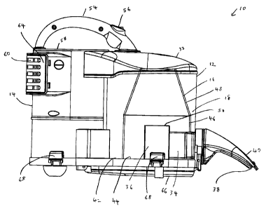
Figure 1 is a side elevational view of a preferred embodiment of a
vacuum cleaner in accordance with this design wherein the outer casing
surrounding the cyclone and forming an outer wall of a dirt collection chamber
is
optionally transparent;
Figure 2 is a perspective view from the front and the right side of the
vacuum cleaner of Figure 1;
-18-
CA 02599303 2007-08-29
Figure 3 is a cross-section along the line 3 - 3 in Figure 2;
Figure 4 is a schematic drawing of the vacuum cleaner of Figure 1
showing the airflow passage therethrough;
Figure 5 is a perspective view from the bottom of the vacuum cleaner of
Figure 1 wherein the bottom of the first and second housings is open;
Figure 6 is a perspective view of the bottom of the vacuum cleaner of
Figure 1 wherein the first and second housings are closed but an access door
is
open;
Figure 7 is a perspective view of the vacuum cleaner of Figure 1 with the
lid removed showing the wire provided to permit the lid to be secured to the
dirt
collection chamber by wire welding;
Figure 8 is an enlargement of area A of Figure 7;
Figures 9A and 9B comprise a perspective view and a top plan view of a
cyclone having a pair of equidistantly spaced ribs used as anti-re-entrainment
members;
Figure 10A and 10B comprise a perspective view and a top plan view of a
cyclone having four equidistantly spaced ribs used as anti-re-entrainment
members;
Figures 11A and 11 B comprise a perspective view and a top plan view of
a cyclone having four unequidistantly spaced ribs used as anti-re-entrainment
members;
Figures 12A and 12B comprise a perspective view and a side elevation
view of a cyclone having a single annular ring provided on the outer surface
of a
cyclone for use as an anti-re-entrainment member;
-19-
CA 02599303 2007-08-29
Figures 13A and 13B comprise a perspective view and a side elevation
view of a cyclone having two spaced apart annular rings provided on the outer
surface of a cyclone for use as anti-re-entrainment members;
Figures 14A, 14B and14C comprise a perspective, top plan and side
view, respectively, of a cyclone having a non-circular annular ring provided
on
the outer surface of the cyclone as an anti-re-entrainment member; and,
Figures 15A, 15B and 15C comprise a perspective, top plan and side
view, respectively, of a cyclone having an elliptical ring positioned at an
angle to
the vertical as an anti-re-entrainment member on the outer surface of the
cyclone.
DETAILED DESCRIPTION
The preferred embodiment set out in Figures 1 - 8 contains each of the
alternate embodiments described in the summary of the invention. These have
been described in a single preferred embodiment for convenience. However,
each may be used individually or in combination with any one or more other
alternate embodiments.
As shown in Figures 1 - 8, a surface cleaning apparatus comprises a
vacuum cleaner 10. It will be appreciated that, surface cleaning apparatus may
be a vacuum cleaner, a carpet extractor, a bare floor cleaner or the like.
Preferably, as exemplified, the surface cleaning apparatus is hand held.
However the surface cleaning apparatus may be configured as an upright
vacuum cleaner, a stick vacuum cleaner, a canister vacuum cleaner, a back
pack or shoulder strap vacuum cleaner or other configuration known in the art.
As exemplified, surface cleaning apparatus 10 has a first housing 12 and
a second housing 14. As exemplified, first housing 12 comprises at least one
cyclone 16 and a dirt collection chamber 18 and second housing 14 houses a
plurality of filters which, preferably, in order comprise foam filter 20, felt
filter 22
-20-
CA 02599303 2007-08-29
and HEPA filter 24 followed in the downstream direction by suction motor 26.
It
will be appreciated that only a single filter may be provided.
In accordance with a first embodiment of this invention, cyclone 16 has a
dirt outlet 28 and an impingement surface 30 spaced from dirt outlet 28 in
dirt
collection chamber 18. As shown in Figure 3, impingement surface 30 is
preferably spaced a distance D from outlet 28 wherein distance D is from 8 to
30
millimeters and, preferably from 12 to 25 millimeters. It will be appreciated
that
impingement member 30 may be mounted to lid 32 of dirt collection chamber
18. Alternately, impingement member may be mounted to a sidewall of dirt
collection chamber 18 and/or cyclone 16.
As exemplified in Figure 3, cyclone 16 is an inverted cyclone.
Accordingly, cyclone 16 has a lower air inlet 34 and a lower air outlet 36.
Air
inlet 34 is positioned downstream from dirty air inlet 38 of surface cleaning
nozzle 40. Surface cleaning nozzle 40 may be any surface cleaning nozzle
known in the art. Air inlet 34 of cyclone 16 may be in airflow communication
with
surface cleaning nozzle 40 in any manner known in the art. The exact structure
of surface cleaning nozzle 40 and the communication passage between surface
cleaning nozzle 40 and air inlet 34 will vary depending if the surface
cleaning
apparatus is an upright vacuum cleaner, canister vacuum cleaner or, as
exemplified, a portable hand held vacuum cleaner. In operation, air will enter
cyclone 16 through inlet 34 and travel upwardly, as exemplified in Figure 4.
The
air will then travel downwardly to exit cyclone 16 via outlet 34. As shown in
Figure 4 by the hatched arrows, dirt will exit upwardly through outlet 28 and
deposit on dirt collection chamber floor 42. In addition, some of the heavier
particulate matter may not be entrained in the air stream and may be deposited
on cyclone floor 34.
In an alternate embodiment, it will be appreciated that cyclone 16 need
not be inverted. Cyclone 16 may be any cyclone with a dirt outlet provided
that
-21 -
CA 02599303 2007-08-29
impingement member or members are positioned spaced from the dirt outlet.
The cyclone may accordingly be upright cyclone or a cyclone having a single
direction of travel of the air.
As exemplified, cyclone 16 is a frustoconical cyclone having cylindrical
portion 46 and frustoconical portion 48. Alternately, or in addition to the
orientation of cyclone 16, it will be appreciated that cyclone 16 may be
cylindrical, entirely frustoconical or any other shape known in the art.
As exemplified in Figure 3, outlet 36 of cyclone 16 comprises a vortex
finder that extends inwardly into the cyclone chamber defined by cyclone 16.
Outlet 36 preferably comprises a generally cylindrical passage having an inlet
50 and an outlet 52. It will be appreciated that, in an alternate embodiment
any
outlet known in the art for cyclones may be utilized. Further, inlet 50 may be
covered by a screen, shroud or filter as in known in the art. In a
particularly
preferred embodiment, it is preferred that no screen, shroud or filter is
provided.
As exemplified in Figures 1 - 8, vacuum cleaner 10 comprises a hand
held vacuum cleaner. Accordingly, vacuum cleaner 10 may be provided with
handle 54, which is affixed to lid 32 and lid 58 of second housing 14. Handle
54
may alternately be affixed to any other portion or portions of vacuum cleaner
10
as is known in the art. Optionally, as exemplified, on/off switch 56 may be
provided on handle 54. On/off switch 56 may alternately be provided on any
other portion of vacuum cleaner 10.
As exemplified in Figure 3, suction motor 26 is positioned in second
housing 14, preferably with a suction fan provided below the electric motor.
Clean air outlet 60 is provided downstream from suction motor 26. An optional
post-motor filter may be provided downstream from suction motor 26, such as in
post-motor filter housing 62, which may be accessible via post motor filter
housing door 64, which could be pivotably mounted to second housing 14.
-22-
CA 02599303 2007-08-29
While the use of the impingement member is exemplified in a surface
cleaning apparatus having side-by-side housings 12, 14, it will be appreciated
that this design may be used in any vacuum cleaner configuration.
In accordance with an alternate preferred embodiment of this invention,
dirt collection chamber 18 surrounds at least a portion of and, as
exemplified,
preferably all of cyclone 16. Accordingly, cyclone 16 may be positioned in
dirt
collection chamber 18 and, preferably, generally centrally therein. In
accordance
with this alternate preferred embodiment, vacuum cleaner 10 is configured such
that the dirt collected on floor 44 of cyclone 16 is emptied at the same time
as
dirt collected on floor 42 of dirt collection chamber 18. Accordingly, floor
42 and
floor 44 are both movable and connected to each other whereby both floor 42
and 44 are concurrently movable such that dirt collection chamber 18 and
cyclone 16 are concurrently emptied.
As exemplified in Figure 5, floors 42 and 44 may comprise a pivoting
bottom of first housing 12 and, alternately, of the filtration apparatus (e.g.
housings 12 and 14 of this embodiment). Accordingly, as seen in Figure 5, when
floors 42 and 44 are opened, both cyclone 16 and dirt collection chamber 18
may be emptied by holding vacuum cleaner 10 in the upright position (as shown
in Figure 1). Accordingly, the dirt will fall out of collection chamber 16 and
cyclone 16 and will fall downwardly off of floors 42 and 44.
As shown in Figure 5, housings 12 and 14 have a pivoting bottom 66,
which is secured to each of housings 12 and 14 by a pivot 68. In the closed
position exemplified in Figures 1 and 4, pivoting bottom 66 is secured in
position
by latch 70. Latch 70 has a button 72 which, when pressed, causes arm 74 to
move outwardly thereby disengaging a flange provided on the bottom end of
arm 74 from flange 76 provided on pivoting bottom 66. A gasket or other
sealing
member may be provided at the interface of housings 12 and 14 and pivoting
bottom 66 to provide an air tight or fluid tight seal. It will be appreciated
that
-23-
CA 02599303 2007-08-29
bottom 66 may be moveable in any other direction by any other means known in
the art and may optionally be removable from housings 12, 14. Further, bottom
66 may be moveably secured in position by any other means known in the art
and need not be connected to surface cleaning apparatus 10 for relative motion
thereto.
As exemplified in Figure 5, outlet 36 is provided as part of floor 42, and is
preferably integrally molded therewith. In an alternate embodiment, it will be
appreciated that outlet 36 need not be removable from cyclone 16 with floor
42.
In an alternate embodiment, it will be appreciated that only floors 42 and
44 may be pivotably mounted to housing 12. In such an embodiment, foam filter
may remain sealed when cyclone 16 and dirt collection chamber 18 are
emptied. In an alternate embodiment, a side-by-side of housings 12, 14 design
as exemplified in Figure 1 need not be utilized. In such a case, floor 42 and
floor
44 may comprise the entire floor of the filtration assembly.
15 If bottom 66 opens both housings 12 and 14, then it will be appreciated
that dirt positioned on the upstream surface of filter 20 will be emptied when
bottom 66 is opened.
In an alternate embodiment, a filtration member is provided adjacent
outlet 36 and, preferably, in sealing engagement with outlet 52. Referring to
20 Figure 3, filtration member 78 is positioned on rear surface 84 of floor 44
and
overlies outlet 52. Accordingly, air that exits outlet 36 travels through
filtration
member 78. The air then travels through filtration chamber 80 and travels
laterally to outlet 86, which is in air flow communication with headspace 88
below filter 20.
Preferably, filtration member 78 comprises a screen, such as an open
mesh screen, e.g., a wire mesh screen or, alternately, a plastic mesh screen.
-24-
CA 02599303 2007-08-29
An access door 82 may be provided to permit access to filtration member
78 such that filtration member 78 may be cleaned. Access door may be any
door that is movably mounted in overlying relationship to filtration chamber
80.
As exemplified in Figure 6, access door 82 is pivotably mounted by pivot 90 to
pivoting bottom 66. Access door 82 may be opened by utilizing a latch 70,
which
engages flange 92 provided on the front end of access door 82. A sealing
gasket or other sealing member known in the art may be utilized to provide an
air tight or fluid tight seal for filtration chamber 80. Any other securing
member
known in the art may be used. Further door 82 may be removable and need not
be connected to surface cleaning apparatus 10 for relative motion thereto.
Preferably, filtration member 78 is mounted and, more preferably,
movably mounted and, most preferably, removably mounted to access door 82.
As shown in Figure 78, filtration member 78 is pivotably mounted to the inner
surface of access door 82. Accordingly, when a user desires to clean
filtration
member 78, it may be pivoted in the direction shown by arrow A in Figure 6 to
an open or cleaning position. It will be noticed that access door 82 may be
opened independently of pivoting bottom 66. In an alternate embodiment, it
will
be appreciated that a pivoting bottom 66 need not be provided.
Preferably, at least a portion of and, more preferably, all of access door
82 is transparent. Accordingly, a user may lift the vacuum cleaner, invert the
vacuum cleaner or tilt the vacuum cleaner on its side to view filtration
member
78 and determine whether filtration 78 requires cleaning or, alternately,
replacement.
As exemplified in Figure 3, vortex finder 36 is not surrounded by a screen
or any shroud or filter. In accordance with a preferred embodiment, vortex
finder
36 has no cover member (e.g. shroud, screen or the like). Accordingly, no
filtration or screen member interior of cyclone 16 requires cleaning.
Accordingly,
-25-
CA 02599303 2007-08-29
it will be appreciated that bottom 44 need not be openable to permit a screen
or
a shroud or filter associated with inlet end 50 of outlet 36 to be cleaned.
In accordance with an alternate preferred embodiment of this invention, a
series of screening and filtration members are used in series downstream from
the cyclone chamber of cyclone 16. In accordance with this preferred
embodiment, the screening and filtration members comprise a screen 78, which
is preferably positioned adjacent outlet 36, a foam filter 22 downstream from
screen 78, a felt filter 22 downstream from foam 20 and a HEPA filter 24
downstream from felt filter 22. Preferably, all of these filters are
positioned
upstream from suction motor 26. Alternately, one or more of these filters may
be
positioned downstream from suction motor 26. In particular HEPA filter 24 may
be downstream from suction motor 26. Accordingly, a plurality of screening and
filtration members, each of which have a finer filtration capacity (e.g.
smaller
pores) are provided in series in the downstream direction. Optionally, a
shroud
(e.g. a perforated or apertured plastic cover) may be provided surrounding or
overlying inlet 50 of outlet 36.
In accordance with another embodiment of this invention, as exemplified
in Figures 9A - 15C, an inverted cyclone 16 may be provided with one or more
anti-re-entrainment members provided on the outer surface of cyclone 16.
Accordingly, the anti-re-entrainment member may comprise one or more ribs 94
provided on the outer surface of cyclone 16 and/or one or more annular rings
96
provided on the outer surface of cyclone 16. As shown in Figures 9A, ribs 94
are
longitudinally extending (i.e. in the direction of the longitudinal axis of
cyclone
16) and may be provided on the frustoconical portion 48 of cyclone 16 or, on
the
cylindrical portion 46 of cyclone 16 (not shown) or on both cylindrical
portion 46
and frustoconical portion 48 of cyclone 16 (see Figures 10A and 10B). It will
be
appreciated that ribs 94 need not extend exactly perpendicular to the
longitudinal axis of cyclone 16 but may be at an angle thereto. In addition,
ribs
-26-
CA 02599303 2007-08-29
94 need not extend from bottom 98 to dirt outlet 28 but may extend for only a
portion of the distance. In addition, ribs 94 need not be continuous, but they
may
have discontinuities. It will be appreciated that ribs 94 may be used on a
cyclone
having any known configuration, and on any part thereof.
As exemplified in Figures 9A, 9B, 10A and 10B, if a plurality of ribs are
provided, they be spaced equidistantly apart (i.e. at equal angular
displacement
from each other). Alternately, as shown in Figures 11A and 11 B, ribs 94
unevenly spaced around the outer surface of cyclone 16.
As exemplified in Figures 12A and 12B, only a single annular ring 96 may
be provided. However, as shown in Figures 13A and 13B, a plurality of rings
may be provided. Rings 96 may be provided on frustoconical portion 48,
cylindrical portion 46 or both frustoconical portion 48 and cylindrical
portion 46. It
will be appreciated that rings 96 may be used on a cyclone having any known
configuration, and on any part thereof.
As exemplified in Figure 14A - C, if a single annular ring is provided, it
need not be provided at the top of cyclone 16 adjacent dirt outlet 28. In
addition,
as exemplified therein, annular ring 46 need not have an outer circular
circumference. Instead, it may have a variety of shapes. For example, as shown
in Figures 14A-C, the outer circumference of ring 96 is hexagonal.
Alternately,
as shown in Figures 15A-C, the outer circumference may be elliptical.
As exemplified in Figures 15A-C, ring 96 need not be provided in a plane
that is perpendicular to the longitudinal axis of cyclone 16. Instead, as
exemplified, ring 96 may be at an angle to the longitudinal axis 100 of
cyclone
16.
As exemplified in Figures 7 and 8, in accordance with another
embodiment, at least two parts of vacuum cleaner 10 may be assembled by wire
welding. Accordingly, an electrically conductive wire 102 having terminal ends
104 and 106 is provided along a surface of a part of the vacuum cleaner (e.g.
-27-
CA 02599303 2007-08-29
top surface 108 of first housing 12). Preferably, wire 102 is provided in a
groove
provided in top surface 108. In accordance with such an embodiment, the top of
wire 102 is preferably flush with top surface 108. Alternately, a portion of
wire
102 may extend upwardly from top surface 108 and may be received in a
groove in the part to be secured to top surface 108.
In order to secure the parts together (e.g. lid 32 and first housing 12), the
parts may be brought into contact prior to or subsequent to terminals 104 and
106 connected to an electrical source (preferably DC) and an electrically
current
applied for a sufficient time to weld lid 32 and first housing 12 together. It
will be
appreciated that as electrical current is applied through wire 102, that the
wire
will heat up thereby melting the surrounding plastic. This permits a complete
airtight or fluid tight seal to be formed between lid 32 and first housing 12.
In a preferred embodiment, ends 112 and 114 of wires do not meet but
are separated by a gap 110. Preferably, this gap is less than 0.08 inches,
more
preferably less than 0.04 inches and, most preferably less than 0.02 inches.
The
advantage of providing a gap 110 is that excessive heating is not provided in
that region. For example, if ends 112 and 114 abutted, additional heat would
be
provided adjacent ends 112 and 114 such that too much of the plastic in that
region may melt to such an extent that the plastic may flow and insufficient
plastic may be provided at a location to provide an air tight or fluid tight
seal.
Accordingly, ends 112 and 114 are preferably spaced apart a sufficient amount
so that the plastic therebetween melts a sufficient amount to provide a full
seal
when current is provided through wire 102.
Subsequent to the wire welding operation, the portions of wire 102 that
extend outwardly from the welded plastic may be bent or cut away. Preferably,
the excess is cut away.
An advantage of using wire welding is that relatively thin walled plastics
may be utilized. In particular, portions of a vacuum cleaner may be assembled
-28-
CA 02599303 2007-08-29
together without screws. If screws are utilized, then the plastic part is
typically
provided with one or more screw ports or one or more ports for receiving a
screw (a screw receiving port). Due to localized stresses, which are
associated
with the use of screws, reinforcing ribs and/or thicker walls are provided in
the
vicinity of the screw port or screw receiving ports. These ribs and thicker
walls
increase the weight of the material and also may complicate construction of a
vacuum cleaner. By using wire welding, reinforcing ribs are not required
since,
once welded, the parts effectively form a unibody construction (e.g.
equivalent to
being integrally molded).
In particular, it is preferred to use wire welding parts which, when
assembled, define an airflow path or a portion thereof. The use of wire
welding
may be used to ensure a full airtight seal is provided, thereby avoiding air
leaks
into a vacuum cleaner (the portions of an air flow passage which are below
atmospheric pressure), which may affect the performance of the cyclone.
It will be appreciated by those skilled in the art that any of the preferred
embodiments may be used singly or in any particular combination or a sub-
combination and that all of these are within the scope of the following
claims. In
addition, it will be appreciated by those skilled in the art that various
modifications and additions may be made to any of these embodiments and all
of those are within the scope of the following claims.
It will also be appreciated that the wire welding technique disclosed
herein may be utilized for other household consumer appliances, such as power
tools, garden tools, and the like.
In particular, it will be noted that the spacing of an impingement surface
may be used alone or in combination with one or more of an anti-re-entrainment
member, a configuration to allow a cyclone chamber and a surrounding dirt
collection chamber to be emptied concurrently, an access door to permit
cleaning or replacement of a filtration member in a filtration chamber
-29-
CA 02599303 2007-08-29
downstream from a cyclone outlet, a filter (preferably a screen) positioned
downstream from a cyclone outlet which is mounted in a housing which is
transparent, a bottom door that opens to expose a filter and permit the filter
to
be cleaned, an embodiment wherein at least two parts are secured together by
wire welding and the use of a screen, foam filter, felt filter and HEPA filter
in
series in a vacuum cleaner, or any particular combination or sub-combination
thereof.
Alternately, it will be noted that a configuration to allow a cyclone
chamber and a surrounding dirt collection chamber to be emptied concurrently
may be used alone or in combination with one or more of the spacing of an
impingement surface, an anti-re-entrainment member, an access door to permit
cleaning or replacement of a filtration member in a filtration chamber
downstream from a cyclone outlet, a filter (preferably a screen) positioned
downstream from a cyclone outlet which is mounted in a housing which is
transparent, a bottom door that opens to expose a filter and permit the filter
to
be cleaned, an embodiment wherein at least two parts are secured together by
wire welding and the use of a screen, foam filter, felt filter and HEPA filter
in
series in a vacuum cleaner, or any particular combination or sub-combination
thereof.
Alternately, it will be noted that an anti-re-entrainment member may be
used alone or in combination with one or more of the spacing of an impingement
surface, a configuration to allow a cyclone chamber and a surrounding dirt
collection chamber to be emptied concurrently, an access door to permit
cleaning or replacement of a filtration member in a filtration chamber
downstream from a cyclone outlet, a filter (preferably a screen) positioned
downstream from a cyclone outlet which is mounted in a housing which is
transparent, a bottom door that opens to expose a filter and permit the filter
to
be cleaned, an embodiment wherein at least two parts are secured together by
-30-
CA 02599303 2007-08-29
wire welding and the use of a screen, foam filter, felt filter and HEPA filter
in
series in a vacuum cleaner, or any particular combination or sub-combination
thereof.
Alternately, it will be noted that an access door to permit cleaning or
replacement of a filtration member in a filtration chamber downstream from a
cyclone outlet may be used alone or in combination with one or more of an anti-
re-entrainment member, a configuration to allow a cyclone chamber and a
surrounding dirt collection chamber to be emptied concurrently, the spacing of
an impingement surface, a filter (preferably a screen) positioned downstream
from a cyclone outlet which is mounted in a housing which is transparent, a
bottom door that opens to expose a filter and permit the filter to be cleaned,
an
embodiment wherein at least two parts are secured together by wire welding
and the use of a screen, foam filter, felt filter and HEPA filter in series in
a
vacuum cleaner, or any particular combination or sub-combination thereof.
Alternately, it will be noted that a filter (preferably a screen) positioned
downstream from a cyclone outlet, which is mounted in a housing which is
transparent may be used alone or in combination with one or more of an anti-re-
entrainment member, a configuration to allow a cyclone chamber and a
surrounding dirt collection chamber to be emptied concurrently, an access door
to permit cleaning or replacement of a filtration member in a filtration
chamber
downstream from a cyclone outlet, the spacing of an impingement surface may
be used, a bottom door that opens to expose a filter and permit the filter to
be
cleaned, an embodiment wherein at least two parts are secured together by wire
welding and the use of a screen, foam filter, felt filter and HEPA filter in
series in
a vacuum cleaner, or any particular combination or sub-combination thereof.
Alternately, it will be noted that a bottom door that opens to expose a filter
and permit the filter to be cleaned may be used alone or in combination with
one
or more of the spacing of an impingement surface, an anti-re-entrainment
-31 -
CA 02599303 2007-08-29
member, an access door to permit cleaning or replacement of a filtration
member in a filtration chamber downstream from a cyclone outlet, a filter
(preferably a screen) positioned downstream from a cyclone outlet which is
mounted in a housing which is transparent, a configuration to allow a cyclone
chamber and a surrounding dirt collection chamber to be emptied concurrently,
an embodiment wherein at least two parts are secured together by wire welding
and the use of a screen, foam filter, felt filter and HEPA filter in series in
a
vacuum cleaner, or any particular combination or sub-combination thereof.
Alternately, it will be noted that an embodiment wherein at least two parts
are secured together by wire welding may be used alone or in combination with
one or more of the spacing of an impingement surface, an anti-re-entrainment
member, an access door to permit cleaning or replacement of a filtration
member in a filtration chamber downstream from a cyclone outlet, a filter
(preferably a screen) positioned downstream from a cyclone outlet which is
mounted in a housing which is transparent, a configuration to allow a cyclone
chamber and a surrounding dirt collection chamber to be emptied concurrently,
a bottom door that opens to expose a filter and permit the filter to be
cleaned
and the use of a screen, foam filter, felt filter and HEPA filter in series in
a
vacuum cleaner, or any particular combination or sub-combination thereof.
Alternately, it will be noted that the use of a screen, foam filter, felt
filter
and HEPA filter in series in a vacuum cleaner may be used alone or in
combination with one or more of the spacing of an impingement surface, an anti-
re-entrainment member, an access door to permit cleaning or replacement of a
filtration member in a filtration chamber downstream from a cyclone outlet, a
filter (preferably a screen) positioned downstream from a cyclone outlet which
is
mounted in a housing which is transparent, a configuration to allow a cyclone
chamber and a surrounding dirt collection chamber to be emptied concurrently,
a bottom door that opens to expose a filter and permit the filter to be
cleaned
-32-
CA 02599303 2007-08-29
and an embodiment wherein at least two parts are secured together by wire
welding, or any particular combination or sub-combination thereof
It will also be appreciated that any of the aforementioned embodiments
may be used singly or in any particular combination or sub-combination of the
remaining features listed above.
-33-