Language selection

Search

Patent 2599722 Summary

Third-party information liability

Some of the information on this Web page has been provided by external sources. The Government of Canada is not responsible for the accuracy, reliability or currency of the information supplied by external sources. Users wishing to rely upon this information should consult directly with the source of the information. Content provided by external sources is not subject to official languages, privacy and accessibility requirements.

Claims and Abstract availability

Any discrepancies in the text and image of the Claims and Abstract are due to differing posting times. Text of the Claims and Abstract are posted:

  • At the time the application is open to public inspection;
  • At the time of issue of the patent (grant).
(12) Patent: (11) CA 2599722
(54) English Title: ADJUSTABLE RATCHET WRENCH
(54) French Title: CLEF A ROCHET AJUSTABLE
Status: Deemed expired
Bibliographic Data
(51) International Patent Classification (IPC):
  • B25B 13/46 (2006.01)
  • B25B 13/16 (2006.01)
(72) Inventors :
  • KINSKEY, TERRY (United States of America)
(73) Owners :
  • INFINITY CONSULTING GROUP, LLC (United States of America)
(71) Applicants :
  • INFINITY CONSULTING GROUP, LLC (United States of America)
(74) Agent: RIDOUT & MAYBEE LLP
(74) Associate agent:
(45) Issued: 2012-09-11
(86) PCT Filing Date: 2006-03-02
(87) Open to Public Inspection: 2006-09-14
Examination requested: 2007-08-30
Availability of licence: N/A
(25) Language of filing: English

Patent Cooperation Treaty (PCT): Yes
(86) PCT Filing Number: PCT/US2006/007512
(87) International Publication Number: WO2006/096482
(85) National Entry: 2007-08-30

(30) Application Priority Data:
Application No. Country/Territory Date
11/070,203 United States of America 2005-03-03
PCT/US05/06791 United States of America 2005-03-03

Abstracts

English Abstract


An adjustable ratchet head assembly has first and second jaw members that are
connected using a pinion shaft and a cogwheel shaft. The pinion shaft has
oppositely threaded end portions that engage oppositely threaded pinion shaft
receiving bores in a central section of each jaw member. The cogwheel shaft
has oppositely threaded end portions that engage oppositely threaded cogwheel
shaft receiving bores in a proximate end of each jaw member. A pinion gear is
concentric with and engages the pinion shaft. A cogwheel gear is concentric
with and engages the cogwheel shaft, and is in driving engagement with the
pinion gear. Driving the cogwheel gear will cause rotation of the cogwheel
shaft, pinion gear and pinion shaft, and will cause the jaw members to move
toward or away from each other. The ratchet head assembly is received in a
cylindrical ratchet head body, which is received in a handle assembly.


French Abstract

La présente invention concerne un ensemble de tête à rochet ajustable qui possède des premier et second éléments de mâchoire qui sont reliés à l~aide d~un arbre de pignon et un arbre de roue dentée. L~arbre de pignon possède des parties d~extrémité filetées de façon opposée qui entrent en prise avec un arbre de pignon fileté de façon opposée recevant des alésages dans une section centrale de chaque élément de mâchoire. L~arbre de roue dentée possède des parties d~extrémité filetées de façon opposée qui entrent en prise avec un arbre de roue dentée fileté de façon opposée recevant des alésages dans une extrémité proche de chaque élément de mâchoire. Un engrenage à pignon est concentrique avec et entre en prise avec l~arbre de pignon. Un engrenage à roue dentée est concentrique avec et entre en prise avec l~arbre de roue dentée, et est en prise d~entraînement avec l~engrenage à pignon. L~entraînement de l~engrenage à roue dentée entraînera la rotation de l~arbre de roue dentée, l~engrenage à pignon et l~arbre de pignon, et forcera les éléments de mâchoire à se rapprocher ou s~éloigner l~un de l~autre. L~ensemble de tête à rochet est reçu dans un corps de tête de rochet cylindrique qui est reçu dans un ensemble de manche.

Claims

Note: Claims are shown in the official language in which they were submitted.


WE CLAIM:


1. An adjustable ratchet head assembly comprising:
first and second opposing elongate jaw members, each jaw
member having: a workpiece engaging distal end;

a central section;
a proximate end;
a threaded pinion shaft receiving bore through said central
section; and a threaded cogwheel shaft receiving bore through
said proximate end;

a pinion shaft having oppositely threaded end portions in threaded
engagement with a respective jaw member threaded pinion
shaft receiving bore;
a pinion gear concentric with said pinion shaft;
a cogwheel shaft having oppositely threaded end portions in threaded
engagement with a respective cogwheel shaft receiving bore;

a cogwheel gear concentric with said cogwheel shaft, said
cogwheel gear in driving engagement with said pinion gear, such
that driving of the cogwheel gear will cause rotation of the
cogwheel shaft, pinion gear and pinion shaft, and will cause the
jaw members to move toward or away from each other;

a generally cylindrical ratchet head body having a diametrical jaw
member/cogwheel shaft receiving slot, said cylindrical body
positioned around said jaw member proximate ends, said cogwheel
shaft, and said cogwheel such that said jaw member proximate
ends and said cogwheel shaft are received in said jaw
member/cogwheel shaft receiving slot, and such that a portion of
said cogwheel gear protrudes from said ratchet head body to act as
a thumbwheel; and

a gear shield member for covering and protecting said pinion gear,


12

wherein said ratchet head body further has a cogwheel gear
receiving slot and a diametrical gear shield receiving bore, said
cogwheel gear receiving slot positioned transverse to said
diametrical jaw member/cogwheel shaft receiving slot for
receiving said cogwheel gear, said gear shield receiving bore
aligned with said cogwheel gear receiving slot along a lower
portion of said ratchet head body, said gear shield received in
openings of said ratchet head body gear shield receiving bore on
the inside of said cogwheel gear receiving slot.


2. The adjustable ratchet head assembly of claim 1, wherein each of said
first and second opposing elongate jaw members has a longitudinal
axis, wherein each said threaded pinion shaft receiving bore is
perpendicular to the respective jaw member longitudinal axis, and
wherein each said cogwheel shaft receiving bore is parallel to the
respective pinion shaft receiving bore, such that said pinion shaft
and said cogwheel shaft have a parallel configuration and are
perpendicular to said jaw member longitudinal axes.


3. The adjustable ratchet head assembly of claim 2, wherein said
pinion shaft further has a central portion, wherein said pinion gear
engages said pinion shaft central portion, wherein said cogwheel shaft
further has a central portion, and wherein said cogwheel gear
engages said cogwheel shaft central portion.


4. The adjustable ratchet head assembly of claim 1, further comprising
a rotation pin, wherein said cogwheel shaft further has a
longitudinal axis and rotation pin receiving bore through said
longitudinal axis of said cogwheel shaft, and wherein said ratchet
head body further has a diametrical rotation pin receiving bore


13

aligned with said jaw member/cogwheel shaft receiving slot and
with said cogwheel shaft rotation pin receiving bore, said rotation
pin extending through said ratchet head body rotation pin receiving
bore and said cogwheel shaft rotation pin receiving bore to rotatably
couple said cogwheel shaft to said ratchet head body.


5. The adjustable ratchet head assembly of claim 1, further having a
protector cap for protecting said cogwheel, said protector cap sized
to fit over the top portion of the ratchet head body, having a
concave upper wall and a cylindrical side wall having an inner
surface, said side wall inner surface having a lip extending
therefrom, wherein said ratchet head body further has a protector
cap lip receiving groove positioned around a top portion of the ratchet
head body, said protector cap lip cooperating with said protector cap
lip receiving groove to hold said protector cap to said ratchet head
body.


6. A ratchet wrench device comprising:
an adjustable ratchet head assembly having:
first and second opposing elongate jaw members, each jaw
member having: a central section;

a proximate end;
a threaded pinion shaft receiving bore through said central
section; and a threaded cogwheel shaft receiving bore through
said proximate end;

a pinion shaft having oppositely threaded end portions in
threaded engagement with a respective jaw member threaded
pinion shaft receiving bore;
a pinion gear concentric with said pinion shaft;
a cogwheel shaft having oppositely threaded end portions in threaded


14

engagement with a respective cogwheel shaft receiving bore;
a cogwheel gear concentric with said cogwheel shaft, said
cogwheel gear in driving engagement with said pinion gear, such
that driving of the cogwheel gear will cause rotation of the
cogwheel shaft, pinion gear and pinion shaft, and will cause the jaw
members to move toward or away from each other;

a cylindrical ratchet head body having:
a diametrical jaw member/cogwheel shaft receiving slot, said jaw
member proximate ends and said cogwheel shaft received in said
jaw member/cogwheel shaft receiving slot such that a portion of
said cogwheel gear protrudes from said ratchet head body to act as a
thumbwheel; and

a ratchet gear around the circumference of said ratchet head
body; and a handle assembly having a ratchet head receiving
structure and a pawl assembly, said cylindrical ratchet head body
received in said handle assembly ratchet head receiving
structure, said pawl assembly cooperating with said ratchet gear
to allow rotation of said ratchet head assembly with respect to said
handle assembly in one direction and to prevent rotation of said
ratchet head assembly in the other direction; and

a gear shield member for covering and protecting said pinion gear,
wherein said ratchet head body further has a cogwheel gear
receiving slot and a diametrical gear shield receiving bore, said
cogwheel gear receiving slot positioned transverse to said jaw
member/cogwheel shaft receiving slot for receiving said cogwheel
gear, said gear shield receiving bore aligned with said cogwheel gear
receiving slot along a lower portion of said ratchet head body, said
gear shield received in openings of said ratchet head body gear
shield receiving bore on the inside of said cogwheel gear receiving
slot.


15

7. The ratchet wrench device of claim 6, said handle assembly
comprising a top handle member having a ring portion and a
bottom handle member having a ring portion, said top handle
member ring portion and said bottom handle member ring portion in
aligned and spaced relation forming said ratchet head receiving
structure, said ratchet gear positioned in the space between said
top handle member ring portion and said bottom handle member
ring portion such that the ratchet head assembly is rotatably
coupled to the handle assembly.


8. The ratchet wrench device of claim 7, said handle assembly further
comprising a spacer member for holding said top handle member
ring portion and said bottom handle member ring portion in said
spaced relation.


9. The ratchet wrench device of claim 8, said top handle member and said
bottom handle member having aligned pivot pin receiving holes, said
pawl assembly comprising:

a pivot pin positioned in said pivot pin receiving holes, said pivot pin
having a top
portion extending beyond an outer surface of a respective one of
said exterior handle members;

a double pawl member having opposed pawls, said double pawl
member attached to said pivot pin and positioned between said top
handle member and said bottom handle member;

a rotation direction lever affixed to said top portion of said pivot
pin, for pivoting one of said opposed pawls against said ratchet gear
for controlling the direction of allowable rotation of said ratchet
head assembly; and


16

a biasing member for applying a biasing force to said double pawl
member to bias said one of said opposed pawls against said
ratchet gear.


10. The ratchet wrench device of claim 9, said handle assembly further
comprising an interior handle member having a cavity adjacent said
double pawl member, said double pawl member further having a
head opposed to said opposed pawls and bearing notches on either
side of said head, said biasing member comprising a spring and ball
bearing assembly positioned in said cavity such that said ball
bearing is biased against said double pawl member in one of said
bearing notches.


11. The adjustable ratchet head assembly of claim 6, further comprising
a rotation pin, wherein said cogwheel shaft further has a
longitudinal axis and rotation pin receiving bore through said
longitudinal axis of said cogwheel shaft, and wherein said ratchet
head body further has a diametrical rotation pin receiving bore
aligned with said jaw member/cogwheel shaft receiving slot and
with said cogwheel shaft rotation pin receiving bore, said rotation
pin extending through said ratchet head body rotation pin receiving
bore and said cogwheel shaft rotation pin receiving bore to rotatably
couple said cogwheel shaft to said ratchet head body.


12. The adjustable ratchet head assembly of claim 6, further having
a protector cap for protecting said cogwheel, said protector cap
sized to fit over the top portion of the ratchet head body, said
protector cap having a concave upper wall and a cylindrical side
wall having an inner surface, said side wall inner surface having a lip
extending therefrom, wherein said ratchet head body further has a
protector cap lip receiving groove positioned around a top portion
of the ratchet head body, said protector cap lip cooperating with


17

said protector cap lip receiving groove to hold said protector cap to
said ratchet head body.


13. A ratchet wrench device comprising:
an adjustable ratchet head assembly having:
first and second opposing elongate jaw members, each jaw
member having: a central section;

a proximate end;
a threaded pinion shaft receiving bore through said central
section; and a threaded cogwheel shaft receiving bore through
said proximate end;

a pinion shaft having oppositely threaded end portions in
threaded engagement with a respective jaw member threaded
pinion shaft receiving bore;
a pinion gear concentric with said pinion shaft;
a cogwheel shaft having oppositely threaded end portions in threaded
engagement with a respective cogwheel shaft receiving bore;

a cogwheel gear concentric with said cogwheel shaft, said
cogwheel gear in driving engagement with said pinion gear, such
that driving of the cogwheel gear will cause rotation of the
cogwheel shaft, pinion gear and pinion shaft, and will cause the jaw
members to move toward or away from each other;

a cylindrical ratchet head body having:
a diametrical jaw member/cogwheel shaft receiving slot, said jaw
member proximate ends and said cogwheel shaft received in said
jaw member/cogwheel shaft receiving slot such that a portion of said
cogwheel gear protrudes from said ratchet head body to act as a
thumbwheel, and

a ratchet gear around the circumference of said ratchet head body;
a handle assembly having a ratchet head receiving structure and a


18

pawl assembly, said cylindrical ratchet head body received in said
handle assembly ratchet head receiving structure, said pawl
assembly cooperating with said ratchet gear to allow rotation of
said ratchet head

assembly with respect to said handle assembly in one direction and to
prevent rotation of said ratchet head assembly in the other direction;
and

a protector cap for protecting said cogwheel, said protector cap sized to fit
over the top portion of the ratchet head body, said protector cap
having a concave upper wall and a cylindrical side wall having an inner
surface, said side wall inner surface having a lip extending therefrom,
wherein said ratchet head body further has a protector cap lip receiving
groove positioned around a top portion of the ratchet head body, said
protector cap lip cooperating with said protector cap lip receiving groove
to hold said protector cap to said ratchet head body.


14. The ratchet wrench device of claim 13, said handle assembly
comprising a top handle member having a ring portion and a bottom
handle member having a ring portion, said top handle member ring
portion and said bottom handle member ring portion in aligned and
spaced relation forming said ratchet head receiving structure, said ratchet
gear positioned in the space between said top handle member ring portion
and said bottom handle member ring portion such that the ratchet head
assembly is rotatably coupled to the handle assembly.


15. The ratchet wrench device of claim 14, said handle assembly further
comprising a spacer member for holding said top handle member ring
portion and said bottom handle member ring portion in said spaced
relation.


19


16. The ratchet wrench device of claim 15, said top handle member and said
bottom handle member having aligned pivot pin receiving holes, said
pawl assembly comprising:

a pivot pin positioned in said pivot pin receiving holes, said pivot pin
having a top
portion extending beyond an outer surface of a respective one of said
exterior handle members;

a double pawl member having opposed pawls, said double pawl member
attached to said pivot pin and positioned between said top handle member
and said bottom handle member;

a rotation direction lever affixed to said top portion of said pivot pin,
for pivoting one of said opposed pawls against said ratchet gear for
controlling the direction of allowable rotation of said ratchet head
assembly; and

a biasing member for applying a biasing force to said double pawl
member to bias said one of said opposed pawls against said ratchet
gear.


17. The ratchet wrench device of claim 16, said handle assembly further
comprising an interior handle member having a cavity adjacent said
double pawl member, said double pawl member further having a head
opposed to said opposed pawls and bearing notches on either side of
said head, said biasing member comprising a spring and ball bearing
assembly positioned in said cavity such that said ball bearing is biased
against said double pawl member in one of said bearing notches.

Description

Note: Descriptions are shown in the official language in which they were submitted.


CA 02599722 2010-03-30
1
FIELD OF THE INVENTION

The present invention relates to a tool for removing bolts and nuts, and in
particular, a ratcheting tool
for bolt or nut removal, which is adjustable to accommodate varying sizes of
bolt heads and nuts.
BACKGROUND OF THE INVENTION

Various tools are used for tightening or loosening bolts and nuts. Two such
tools are an open-ended
wrench and a closed-ended wrench. Both types of wrenches have a specific
opening to accommodate
corresponding size bolt heads or nuts. In order to accommodate different sizes
of bolt heads or nuts,
one would need different wrenches having different corresponding opening
sizes.

One advancement over individual open-ended or closed-ended wrenches is an
adjustable spanner or
wrench having an adjustable opening to accommodate varying sizes of bolts or
nuts, depending on the
adjustment of the jaw opening.

An alternative design to open-ended, closed-ended and adjustable wrenches is a
socket wrench, which
includes a ratchet and a socket end for accepting a plurality of different
size interchangeable sockets.
Each socket is specifically dimensioned to accommodate a specific size bolt
head or nut. An advantage of
a socket wrench is its ratcheting feature which allows selective movement in
either a clockwise or
counterclockwise direction relative to the handle of the wrench thereby
providing for what is know in
the art as a "ratcheting action" to allow one to quickly loosen or tighten a
bolt or nut.

A disadvantage of conventional adjustable wrenches is that they do not provide
a ratcheting action.
Therefore, these wrenches do not allow one to quickly and easily tighten or
loosen a bolt or nut by
rotating the wrench over a desired arc or degree of rotation around the bolt
or nut. A disadvantage with
conventional socket wrenches is that, since the sockets are not adjustable,
one needs a specific socket
for each different size bolt or nut one wishes to adjust. Since bolts and nuts
come in variety of different
sizes including both English and metric units, one needs to have numerous
sockets at his or her disposal
in order to accommodate these different sizes of bolts and nuts.

Accordingly, there is a need in the art for an improved tool which provides
fast and easy bolt and nut
removal using an adjustable tool.

SUMMARY OF THE INVENTION

The present invention meets this need and others with a novel adjustable
ratchet head assembly, and a
novel ratchet wrench device.

The adjustable ratchet head assembly has first and second jaw members that are
connected using a
pinion shaft and a cogwheel shaft. The pinion shaft has oppositely threaded
end portions that engage
oppositely threaded pinion shaft receiving bores in a central section of each
jaw member. The cogwheel
shaft has oppositely threaded end portions that engage oppositely threaded
cogwheel shaft receiving
bores in a proximate end of each jaw member. The jaw members also have a
distal workpiece engaging


CA 02599722 2010-03-30
2

end. Rotation of the pinion shaft and cogwheel shaft will cause the jaw
members to move toward or
away from each other. A pinion gear is concentric with and engages the pinion
shaft. A cogwheel gear is
concentric with and engages the cogwheel shaft, and is in driving engagement
with the pinion gear.
Thus, driving the cogwheel gear will cause rotation of the cogwheel shaft,
pinion gear and pinion shaft,
and will cause the jaw members to move toward or away from each other.

The proximate ends of the jaw members and the cogwheel shaft are received in a
diametrical jaw
member / cogwheel shaft receiving slot of a cylindrical ratchet head body. The
cylindrical ratchet head
body also has a ratchet gear around its circumference.

A handle assembly of the invention has a ratchet head receiving structure and
a pawl assembly. The
cylindrical ratchet head body is received in the handle assembly ratchet head
receiving structure. The
pawl assembly cooperates with the ratchet gear to allow rotation of the
ratchet head assembly with
respect to the handle assembly in one direction and to prevent rotation of the
ratchet head assembly in
the other direction.

BRIEF DESCRIPTION OF THE DRAWINGS

The invention will now be described in more detail with reference to the
accompanying drawing, in
which:

FIG. 1 is a perspective view of an exemplary adjustable ratchet wrench device
according to the
invention;

FIG. 2 is an exploded view of the primary components of the adjustable ratchet
wrench device of FIG. 1;
FIG. 3a is a top view of selected parts of an exemplary ratchet head assembly,
pawl assembly, and
interior handle member according to various aspects of the invention (an
exemplary bottom handle
member is partially show in broken line representation);

FIG. 3b is a side view of the exemplary ratchet head assembly of FIG. 3a;
FIG. 3c is a bottom view of the exemplary ratchet head assembly of FIG. 3a;

FIG. 4 is a partial sectional view of an exemplary ratchet head assembly
according to an aspect of the
invention (for clarity of understanding, selected elements are shown in
section while other elements are
shown in plan); and

FIG. 5 is a perspective view of an exemplary hand grip member according to an
aspect of the invention.
DETAILED DESCRIPTION

As shown in FIG. 1, an exemplary embodiment of an adjustable ratchet wrench
device 10 according to
the invention has, generally, a handle assembly 12 and an adjustable ratchet
head assembly 14. Visible
elements of the handle assembly 12 include a handle section 16, a hand grip
member 18 covering a


CA 02599722 2010-03-30
3

portion of the handle section 16, a top handle member 20, a bottom handle
member 21, a spacer
member 22, and a rotation direction lever 24 of a pawl assembly. Visible
elements of the ratchet head
assembly 14 include first and second opposing jaw members 26, 27, a pinion
shaft 28, a gear shield 30, a
protector cap 32, and a thumbwheel 34.

Driving the thumbwheel 34 will move the jaw members 26, 27 toward each other
or away from each
other, according to the direction of rotation of the thumbwheel 34. The jaw
members 26, 27 may be
moved away from each other to accommodate a bolt head or nut, and then moved
toward each other
to engage the bolt head or nut for tightening or loosening. The handle
assembly 12 holds the ratchet
head assembly 14 fixed in one direction of rotation, and allows the ratchet
head assembly 14 to freely
rotate in the other direction of rotation, so that the handle assembly 12 can
be brought back to recover
the stroke without removing the jaw members 26, 27 from the bolt head or nut.
The rotation direction
lever 24 determines whether ratchet head assembly 14 is fixed in the clockwise
or counter-clockwise
direction with respect to the handle assembly 12, and allows the direction to
be switched for tightening
or loosening of the bolt or nut.

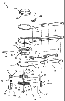
FIG. 2 is an exploded view of the exemplary adjustable ratchet wrench device
10. The adjustable ratchet
head assembly 14 has first and second opposing jaw members 26, 27, a pinion
shaft 28 having a pinion
gear 36, a cogwheel shaft 38 having a cogwheel gear 40, a ratchet head body
42, a rotation pin 44, a
gear shield 46, and a protector cap 32. The handle assembly 12 has a top
handle member 20, a bottom
handle member 21, an interior handle member 50, a spacer member 22, and a pawl
assembly 52.

Each of the first and second opposing jaw members 26, 27 is an elongate
structure having a longitudinal
axis and having a distal end 56, 57, a central section 58, 59, and a proximate
end 60, 61. The distal end
56, 57 of each jaw member 26, 27 is the end that engages the bolt head, nut,
or other workpiece. Each
central section 58, 59 has a threaded pinion shaft receiving bore 62, 63 that
is perpendicular to the
longitudinal axis and extends through the member 26, 27. Each threaded pinion
shaft receiving bore 62,
63 is threaded in an opposite direction from the other pinion shaft receiving
bore 63, 62. Each proximate
end 60, 61 has a threaded cogwheel receiving bore 64, 65 that is parallel to
the pinion shaft receiving
bore 62, 63 and also extends through the member 26, 27. Each threaded cogwheel
receiving bore 64, 65
is also threaded in an opposite direction from the other cogwheel receiving
bore 65, 64.

The pinion shaft 28 has oppositely threaded end portions 66, 67 and a central
portion 68. The pinion
gear 36 is concentric with and engages the central portion 68 of the pinion
shaft 28 between the
oppositely threaded end portions 66, 67, such that when the pinion gear 36 is
driven, the pinion shaft 28
will rotate. The pinion gear 36 may be integral with the pinion shaft 28, or
may be otherwise fastened,
attached, affixed, joined, connected, or coupled to the pinion shaft 28. Each
of the pinion shaft
oppositely threaded end portions 66, 67 is received in and threadedly engaged
with a respective jaw
member threaded pinion shaft receiving bore 62, 63, such that rotation of the
pinion shaft 28 in the
pinion shaft receiving bores 62, 63 will cause the jaw members 26, 27 to move
toward or away from
each other.


CA 02599722 2010-03-30
4

The cogwheel shaft 38 also has oppositely threaded end portions 70, 71 and a
central portion 72. The
cogwheel gear 40 is concentric with and engages the central portion 72 of the
cogwheel shaft 38
between the oppositely threaded end portions 70, 71, such that when the
cogwheel gear 40 is driven,
the cogwheel shaft 38 will rotate. The cogwheel gear 40 may be integral with
the cogwheel shaft 38, or
may be otherwise fastened, attached, affixed, joined, connected, or coupled to
the cogwheel shaft 28.
Additionally, the cogwheel shaft 38 has a rotation pin receiving bore 74
through a longitudinal axis of
the cogwheel shaft 38. Each of the cogwheel shaft oppositely threaded end
portions 70, 71 is received in
and threadedly engaged with a respective jaw member cogwheel shaft receiving
bore 64, 65, such that
rotation of the cogwheel shaft 38 in the cogwheel shaft receiving bores 64, 65
will cause the jaw
members 26, 27 to move toward or away from each other. The cogwheel shaft 38
and pinion shaft 28
have a parallel configuration and are perpendicular to the longitudinal axes
of the first and second
opposing jaw members 26, 27.

The pinion shaft receiving bores 62, 63, cogwheel shaft receiving bores 64,
65, pinion shaft 28, pinion
gear 36, cogwheel shaft 38 and cogwheel gear 40 are located and scaled such
that the cogwheel gear 40
engages the pinion gear 36. The cogwheel gear 40 is also referred to as a
"thumbwheel 34" because in
use, it is driven by a user's thumb to open and close the jaw members 26, 27.
When the user drives the
cogwheel gear / thumbwheel 40 (34), the parallel pinion shaft 28 and cogwheel
shaft 38 rotate and the
jaw members 26, 27 ride on the pinion shaft 28 and cogwheel shaft 38 toward or
away from each other.
Advantageously, the parallel pinion shaft 28 and cogwheel shaft 38 arrangement
provides smooth,
stable, even and easy adjustment of the jaw members 26, 27, and adds clamping
force to counter the
rotational moments created when the distal, workpiece engaging ends 56, 57 of
the jaws 26, 27 are
tightened around a bolt head, nut, or other workpiece. The gears and threads
are also selected to
maintain the jaw members 26, 27 in a proportional relationship. In the
exemplary embodiment, the
cogwheel gear 40 and threaded end portions 70, 71 of the cogwheel shaft 38
have a ratio with the
pinion gear 36 and threaded end portions 66, 67 of the pinion shaft 28 such
that one revolution of the
cogwheel gear 40 will advance the pinion gear 36 two revolutions.

As shown in FIG. 3a, FIG. 3b, FIG. 3c, and FIG. 4, the ratchet head body 42
has a generally cylindrical
body 76, a diametrical jaw member / cogwheel shaft receiving slot 78 for
receiving the proximate ends
60, 61 of the jaw members 26, 27 and the cogwheel shaft 38, a diametrical
cogwheel gear receiving slot
80 for receiving the cogwheel gear 40, a rotation pin 44 (shown in FIG. 2 and
in broken line
representation in FIG. 4), and a ratchet gear 84. The cogwheel gear receiving
slot 80 is transverse to the
jaw member / cogwheel shaft receiving slot 78. The ratchet head body 42 is
positioned around the
proximate ends 60, 61 of the jaw members 26, 27, the cogwheel shaft 38, and
the cogwheel gear 40
such that the proximate ends 60, 61 of the jaw members 26, 27 and the cogwheel
shaft 38 are received
in the jaw member / cogwheel shaft receiving slot 78, and such that the
cogwheel gear 40 is received in
the cogwheel gear receiving slot 80. A portion of the cogwheel gear 40
protrudes from the ratchet head
body 42 to act as a thumbwheel 34.

Shown in FIG. 2 and FIG. 4, the ratchet head body 42 also has a diametrical
rotation pin receiving bore
86 aligned with the jaw member / cogwheel shaft receiving slot 78 and with the
cogwheel shaft rotation


CA 02599722 2010-03-30

pin receiving bore 74. The rotation pin 44 extends through the ratchet head
body rotation pin receiving
bore 86 and the cogwheel shaft rotation pin receiving bore 74 to rotatably
couple the cogwheel shaft 38
to the ratchet head body 42.

Shown in FIG. 2 through FIG. 4, the ratchet gear 84 engages the circumference
of the ratchet head body
5 42, such that jamming of the ratchet gear 84 will prevent rotation of the
ratchet head body 42. The
ratchet gear 84 may be integral with the ratchet head body 42, or may be
otherwise fastened, attached,
affixed, joined, connected, or coupled to the ratchet head body 42.

Additionally, the ratchet head body 42 has a diametrical gear shield receiving
bore 88 aligned with the
cogwheel gear receiving slot 80 along a lower portion of the ratchet head body
42, and a protector cap
lip receiving groove 90 positioned around a top portion of the ratchet head
body 42.

The gear shield member 46 is received in the openings of the ratchet head body
gear shield receiving
bore 88 on the inside of the cogwheel receiving slot 80. The gear shield
member 46 covers and protects
the cogs or teeth of the pinion gear 36 from damage from the workpiece or
other objects that may pass
between the jaw members 26, 27. In the exemplary embodiment, the gear shield
member 46 has a one-
piece construction and follows the curvature of the pinion gear 36. The gear
shield member 46 is
resilient, which allows it to be flexed such that its ends can be inserted
into the openings of the ratchet
head body shield receiving bore 88 on the inside of the cogwheel receiving
slot 80.

Similarly, best shown in FIG. 4, the protector cap 32 protects the top portion
of the ratchet head body
42 and the cogwheel gear 40. The protector cap 32 is sized to fit over the top
portion of the ratchet
head body 42, and has a concave upper wall. The protector cap 32 protects the
cogwheel gear 40,
provides comfort for the user's thumb, and provides an aesthetic benefit (i.e.
makes it "meaner
looking") to the ratchet wrench device 10. The protector cap 32 has a
cylindrical side wall 92 having an
inner surface 94. A lip 96 extends from the inner surface 94, and cooperates
with the protector cap lip
receiving groove 90 positioned around the top portion of the ratchet head body
42 to hold the protector
cap 32 to the ratchet head body 42.

Returning now to FIG. 2, the top handle member 20 and bottom handle member 21
have aligned ring
portions 98, 99 in spaced relation forming a ratchet head receiving structure.
The interior handle
member 50 and the spacer member 22 hold the top handle member 20 and bottom
handle member 21
in such spaced relation. The ratchet head body 42 is received within the
ratchet head receiving structure
with the ratchet gear 84 positioned in the space between the top handle member
ring portion 98 and
bottom handle member ring portion 99 such that the ratchet head assembly 14 is
rotatably coupled to
the handle assembly 12. The spacer member 22 has a height greater than the
width of the ratchet gear
84 to facilitate rotation of the ratchet head assembly 14 in the ratchet head
receiving structure of the
handle assembly 12.

Shown in FIG. 2 and FIG. 3a, the pawl assembly 52 cooperates with the ratchet
gear 84 to allow rotation
of the ratchet head assembly 14 with respect to the handle assembly 12 and to
prevent rotation of the
ratchet head assembly 14 in the other direction. The pawl assembly 52 has a
double pawl member 100,


CA 02599722 2010-03-30
6

a rotation direction lever 24, and a biasing member 102. The double pawl
member 100 has opposed
pawls 104, 105 and a pivot pin 106 extending through or from top and bottom
surfaces of the double
pawl member 100. The pivot pin 106 extends through aligned holes 108, 109 in
the top handle member
20 and bottom handle member 21, respectively, to engage the double pawl member
100 and to pivot
one of the pawls 104, 105 against the ratchet gear 84. The pivot pin 106 may
engage the double pawl
member 100 through a flat spot or other irregular shape in the pin 106 which
acts on a mating opening
in the double pawl member 100. Alternatively, the pivot pin 106 may be
integral with the double pawl
member 100. The rotation direction lever 24 is attached to the portion of the
pivot pin 106 extending
through the hole 108 in the top handle member 20. The biasing member 102
applies a biasing force to
the double pawl member 100 to bias one of the opposed pawls 104, 105 against
the ratchet gear 84,
which jams the ratchet gear 84 in one direction of rotation, and allows
movement in the other direction
of rotation. Thus, the biasing member 102 holds the double pawl member 100 in
the selected
orientation until a changing force is applied to the rotation direction lever
24 to overcome the biasing
force and change the direction of allowable rotation of the ratchet head
assembly 14.

In the exemplary embodiment, the biasing member is a spring 110 and ball
bearing 112 assembly. The
spring 110 and ball bearing 112 assembly is positioned in a cavity 114 in the
interior handle member 50
adjacent the double pawl member 100. The double pawl member 100 has a head 116
and bearing
notches 118, 119 on either side of the head 116. The head 116 is opposed to
the opposed pawls 104,
105, in a substantially triangular arrangement. The spring 110 and ball
bearing 112 assembly cooperates
with the head 116 and bearing notches 118, 119 such that the ball bearing 112
is biased against the
double pawl member 100 in one of the bearing notches 118, 119 to provide the
biasing force.

The top handle member 20, bottom handle member 21, and interior handle member
50 are held
together by fasteners, such as rivets, as needed.

As shown in FIG. 1 and FIG. 5, the hand grip member 18 of the exemplary
embodiment is a boot that
slides over a portion of the handle section 16 of the handle assembly 12, to
provide ergonomic
adaptation of the ratchet wrench device 10 to a human hand. Advantageously,
the end of the hand grip
member 18 may contain a socket 120 for holding a tool bit.

Additionally, the words "right" and "left" may be added to the top handle
member 20 adjacent the
rotation direction lever 24 to provide a visual indication with the lever 24
pointing to the direction of
fixed rotation of the ratchet wrench device 10. Likewise, the words "open" and
"close" may be added to
the protector cap 32 to provide a visual indication of the rotation direction
of the thumbwheel 34 to
open and close the jaw members 26, 27.

Referring now to FIG. 2, the inner surfaces 122, 123 of the jaw members 26, 27
can be magnetized to
allow for positioning of a screw-driver bit for use of the device as a
standard screw driver.

Although the invention has been described in considerable detail with respect
to exemplary
embodiments, it will be apparent to those skilled in the art that the
invention is capable of numerous
modifications and variations without departing from the spirit and scope of
the claimed invention.

Representative Drawing
A single figure which represents the drawing illustrating the invention.
Administrative Status

For a clearer understanding of the status of the application/patent presented on this page, the site Disclaimer , as well as the definitions for Patent , Administrative Status , Maintenance Fee  and Payment History  should be consulted.

Administrative Status

Title Date
Forecasted Issue Date 2012-09-11
(86) PCT Filing Date 2006-03-02
(87) PCT Publication Date 2006-09-14
(85) National Entry 2007-08-30
Examination Requested 2007-08-30
(45) Issued 2012-09-11
Deemed Expired 2016-03-02

Abandonment History

There is no abandonment history.

Payment History

Fee Type Anniversary Year Due Date Amount Paid Paid Date
Request for Examination $400.00 2007-08-30
Application Fee $200.00 2007-08-30
Maintenance Fee - Application - New Act 2 2008-03-03 $50.00 2008-02-26
Maintenance Fee - Application - New Act 3 2009-03-02 $50.00 2009-02-12
Maintenance Fee - Application - New Act 4 2010-03-02 $50.00 2010-03-02
Maintenance Fee - Application - New Act 5 2011-03-02 $100.00 2011-01-24
Maintenance Fee - Application - New Act 6 2012-03-02 $200.00 2012-03-01
Final Fee $300.00 2012-06-28
Maintenance Fee - Patent - New Act 7 2013-03-04 $200.00 2013-02-27
Maintenance Fee - Patent - New Act 8 2014-03-03 $100.00 2014-02-24
Owners on Record

Note: Records showing the ownership history in alphabetical order.

Current Owners on Record
INFINITY CONSULTING GROUP, LLC
Past Owners on Record
KINSKEY, TERRY
Past Owners that do not appear in the "Owners on Record" listing will appear in other documentation within the application.
Documents

To view selected files, please enter reCAPTCHA code :


To view images, click a link in the Document Description column. To download the documents, select one or more checkboxes in the first column and then click the "Download Selected in PDF format (Zip Archive)" or the "Download Selected as Single PDF" button.

List of published and non-published patent-specific documents on the CPD .

If you have any difficulty accessing content, you can call the Client Service Centre at 1-866-997-1936 or send them an e-mail at CIPO Client Service Centre.


Document
Description 
Date
(yyyy-mm-dd) 
Number of pages   Size of Image (KB) 
Abstract 2007-08-30 2 87
Claims 2007-08-30 6 268
Drawings 2007-08-30 5 109
Description 2007-08-30 10 507
Representative Drawing 2008-01-17 1 14
Cover Page 2008-01-17 2 53
Claims 2011-07-26 9 352
Claims 2010-03-30 4 195
Description 2010-03-30 6 384
Cover Page 2012-08-15 2 54
Fees 2008-02-26 1 35
Prosecution-Amendment 2011-07-26 16 627
PCT 2007-08-30 1 57
Assignment 2007-08-30 4 125
Fees 2010-03-02 1 34
Fees 2009-02-12 1 34
Prosecution-Amendment 2009-10-05 2 54
Prosecution-Amendment 2010-03-30 13 683
Prosecution-Amendment 2011-01-26 3 86
Fees 2011-01-24 1 35
Correspondence 2012-06-28 1 49