Note: Descriptions are shown in the official language in which they were submitted.
CA 02599728 2007-08-30
WO 2006/101573 PCT/US2006/000574
COATINGS FOR USE ON MEDICAL DEVICES
FIELD OF THE INVENTION
The present invention relates to the field of delivery systems for medical
devices, in particular, to expandable members employed for the delivery of
stents, and to
coatings employed thereon, as well as to methods of making and using the same.
BACKGROUND OF THE INVENTION
Medical device such as stents and stent delivery assemblies are utilized in
a number of medical procedures, and as such their structure and function are
well
known. A stent is a generally cylindrical radially expandable prosthesis
introduced
percutaneously via a catheter into a lumen of a body vessel in a configuration
having a
generally reduced diameter and then expanded to the diameter of the vessel. In
its
expanded configuration, the stent supports and reinforces the vessel walls
while
maintaining the vessel in an open, unobstructed condition.
Stents may be implanted in a variety of body lumens or vessels such as
within the vascular, urethral, ureteral, reproductive, biliary, neurological,
tracheal,
cerebral, gastrointestinal, esophageal systems, etc.
Both self-expanding and inflation expandable stents are well-known and
widely available. Self-expanding stents are typically maintained under
positive external
pressure in order to maintain their reduced diameter configuration during
delivery of the
stent to its deployment site. Inflation expandable stents are generally
crimped to their
reduced diameter about an expandable member of a delivery device, positioned
at the
deployment site, and expanded via outward radial pressure such as provided
during
inflation of the expandable member.
During a medical procedure, the stent is positioned in a precise location
within a bodily lumen. To facilitate the proper positioning of a stent, it is
desirable to
prevent any unwanted relative movement between any of the stent, the balloon,
the
catheter and the interior of the vessel. This goal is rendered more difficult
because the
trend in stent design is to utilize thinner and more flexible structures which
provide less
radial inward force in the crimped state, hence there is less securement
between the
balloon and the stent. Slippage may occur during insertion of the stent
through a guide
catheter, while crossing tortuous anatomy, or during deployment of the stent.
CA 02599728 2007-08-30
WO 2006/101573 PCT/US2006/000574
The issue of slippage of a stent relative to a balloon has been dealt with in
several different ways including by varying the coefficient of friction of the
exposed
portion of a balloon between the uninflated and inflated states of the
balloon. Another
approach involves providing a balloon with enlarged ends and a middle section
of
reduced diameter to retain a stent. Other approaches are non-balloon based,
providing
stent retention devices that extend from the catheter and engage the stent.
It is known to fabricate multi-layer films using the concept of
electrostatic interaction between oppositely charged species during a stepwise
absorption
from an aqueous solution. Such multi-layer films have been employed in making
capsules and in the development of functional colloidal particles.
SUMMARY OF THE INVENTION
It is a goal of the present invention to provide a medical device delivery
system using novel coating technology to improve medical device deployment
accuracy
by preventing slippage of the medical device during delivery of the device to
the desired
bodily location and during deployment of the device so as to facilitate the
positioning of
a medical device with greater precision.
In one aspect, the present invention relates to a novel coating for use on
medical device components.
In one aspect, the novel coating is employed on components of catheter
assemblies.
In one aspect, the novel coating is employed on an expandable medical
balloon.
In another aspect, the expandable medical balloon may be disposed on
the distal end of a catheter delivery assembly and used for securement of an
intraluminal
medical device during delivery to a deployment site within a patient's body
lumen. The
novel coatings according to the invention are disposed on at least a portion
of the
expandable medical balloon, the intraluminal medical device, or both.
In another aspect, a self-expanding intraluminal medical device is
disposed about an inner member of a catheter delivery assembly, a degradable
coating
according to the invention is provided for securement of the self-expanding
intraluminal
medical device to the inner member.
The novel coating is suitably biocompatible, may be rapidly degrading or
dissolving, and is applied as a thin layer to the medical device components.
2
CA 02599728 2007-08-30
WO 2006/101573 PCT/US2006/000574
In one aspect, the coating is a layer-by-layer (LbL) coating having at least
one first layer and one second layer, the first layer including a positively
charged
material, and the second layer adjacent the first layer including a negatively
charged
material.
Alternatively, the first layer may include a negatively charged material
and the second layer may include a positively charged material as well.
In any of the embodiments described herein, a therapeutic agent or
mixtures of therapeutic agents may be optionally employed.
Furthermore, the present invention can be employed in combination with
a drug eluting coating layer.
In one embodiment, the degradable coating is einployed as an
intermediate layer between a medical balloon and a stent having a drug eluting
coating
layer.
The coating is sufficiently strong to secure an intraluminal medical
device during delivery to deployment sites within a patient's vasculature, but
yet allows
the intraluminal medical device to expand and release from an expandable
balloon
member once the expandable balloon member has been deflated.
These and other aspects, embodiments and advantages of the present
invention will become immediately apparent to those of ordinary skill in the
art upon
review of the Detailed Description and Claims to follow.
BRIEF DESCRIPTION OF THE DRAWINGS
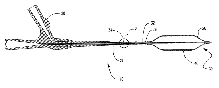
FIG. 1 is a longitudinal cross-sectional side view of a catheter assembly
having a balloon of the present invention mounted thereon and a stent disposed
on the
balloon.
FIG. 2 is an enlarged view taken at section 2 in FIG. 1.
FIG. 3 is a longitudinal side view of a stent disposed on a medical
balloon.
FIG. 4 is a longitudinal side view of a stent disposed on a medical balloon
and having a coating according to the invention disposed over the stent and
balloon.
FIG. 5 is a longitudinal side view of a stent and medical balloon similar
to that shown in FIG. 4 with the balloon inflated and the stent in an expanded
form.
3
CA 02599728 2007-08-30
WO 2006/101573 PCT/US2006/000574
FIG. 6 is a longitudinal side view of a stent and balloon similar to that
shown in FIG. 5 with the stent expanded and the balloon contracted and shown
within a
body vessel.
FIG. 7 is a fragmentary cross-section of a stent and balloon taken along
the longitudinal axis of the balloon and having a layer-by-layer coating
disposed
between according to the invention.
FIG. 8 is a fragmentary cross-section of a stent and balloon similar to that
shown in FIG. 7 taken along the longitudinal axis of the balloon with the
stent shown in
contact with a body vessel.
FIG. 9 is a fragmentary cross-section of a stent and balloon similar to that
shown in FIG. 8 taken along the longitudinal axis of the balloon with the
stent in an
expanded state and the balloon in a contracted state.
FIG. 10 is a fragmentary cross-section of a stent and balloon taken along
the longitudinal axis of the balloon and having an alternative embodiment of a
layer-by-
layer coating according to the invention.
FIG. 11 is a fragmentary cross-section of a stent and balloon similar to
that shown in FIG. 10 taken along the longitudinal axis of the balloon, the
stent crimped
on the balloon.
FIG. 12 is a fragmentary cross-section of a stent and balloon similar to
that shown in FIGS. 10-11 taken along the longitudinal axis of the balloon,
the stent in
an expanded state and the balloon in a contracted state within a body vessel
prior to
withdrawal of the balloon.
FIG. 13 is a longitudinal side view of a stent disposed on a balloon and
having a coating disposed over both the stent and the balloon according to the
invention.
FIG. 14 is an exploded fragmentary cross-section taken at 14 in FIG. 13
showing a therapeutic agent(s) disposed between stent struts.
FIG. 15 is a fragmentary cross-section of a stent and balloon taken along
the longitudinal axis of the balloon illustrating an alternative embodiment of
the coating
according to the invention.
FIG. 16 is a fragmentary cross-section of a stent and balloon similar to
that shown in FIG. 15, with the stent in an expanded state and in contact with
a vessel
wall.
4
CA 02599728 2007-08-30
WO 2006/101573 PCT/US2006/000574
FIG. 17 is a fragmentary cross-section of a stent and a balloon similar to
that shown in FIGS. 15 and 16 illustrating another embodiment according to the
invention.
FIG. 18 is a fragmentary cross-section of a stent and balloon similar to
that shown in FIG. 17, with the stent in an expanded state and in contact with
a vessel
wall.
FIG. 19 is a partial longitudinal view of a coating employed in
combination with a self-expanding stent and delivery system.
FIG. 20 is a partial longitudinal cross-sectional view of another
embodiment of a coating employed in combination with a self-expanding stent
and
delivery system according to the invention.
FIG. 21 is a partial longitudinal cross-sectional view is a partial
longitudinal cross-sectional view of another embodiment of a coating employed
in
combination with a self-expanding stent and delivery system according to the
invention.
DETAILED DESCRIPTIONS OF THE PREFERRED EMBODIMENTS
While this invention may be embodied in many different forms, there are
described in detail herein specific preferred embodiments of the invention.
This
description is an exemplification of the principles of the invention and is
not intended to
limit the invention to the particular embodiments illustrated.
In one aspect, the present invention relates to novel coatings for medical
devices. The novel coatings may find utility on any type of intraluminal
medical device
including, but not limited to, any type of catheter assembly or component
thereof, stents,
stent-grafts, grafts, vena cava filters, embolization devices, medical
balloons, etc.
Examples of the various types of catheter assemblies include, but are not
limited to, guide catheters, catheter for delivery of medical devices,
diagnostic catheters,
etc.
Catheter assemblies including those used for the delivery of other
medical devices such as stents, are employed in a variety of body lumens
including those
found in the vascular system, biliary system, neurological system,
reproductive system,
urinary system, gastrointestinal system, etc.
FIG. 1 is a longitudinal cross-sectional side view of a catheter assembly
10 according to the invention. Balloon 20 is mounted on the distal end 30 of
catheter 10.
A balloon expandable stent 40 is disposed on balloon 20.
5
CA 02599728 2007-08-30
WO 2006/101573 PCT/US2006/000574
Catheter 10 is a representative simple over-the-wire (OTW) or single-
operator-exchange (SOE) balloon catheter according to the invention. Such
balloon
catheters are discussed are well known. In this embodiment, catheter 10 has an
elongate
shaft assembly 26 and a conventional OTW-type manifold assenibly 28 connected
to
proximal end of shaft assembly 26. The shaft assembly 26 includes an inner
shaft 32
and an outer shaft 34. Outer shaft 34 is coaxially disposed about inner shaft
32 to define
an annular inflation lumen 36 shown in enlarged fragmentary cross-section in
FIG. 2
which is taken at section 2 in FIG. 1. Balloon 20 may be inflated by passing
inflation
fluid through manifold 28 resulting in deployment of stent 40. Negative
pressure may
then be applied to deflate and contract balloon 20. Procedures of this type
are known in
the art. Other catheter configurations are known which may also be employed
herein.
The invention is not limited by the type of catheter illustrated above.
The novel coatings according to the invention may be applied to balloon
20, stent 40 or a combination thereof. Furthermore, as described in various
embodiments below, the novel coatings according to the invention may be
applied to an
inner member of a catheter delivery assembly employed in combination with self-
expanding intraluminal medical devices.
The coatings herein are suitably degradable. In a typical embodiment, the
coating shall be selected so as to degrade within an environment within a
patient's body.
This degradation may occur through any mechanism such as by at least partial
dissolution as in an aqueous environment, or by a weakening of an ionic bond,
hydrogen
bond, van der Waals forces, or weakening of some other interaction. The
invention is
not limited by the type of mechanism which results in degradation or weakening
of the
coating.
This term degradation may also refer to decomposition wherein one
substance breaks down into two simpler substances.
In an embodiment wherein a stent is disposed about the expandable
member of a catheter assembly for deployment of the stent in a body vessel,
the force of
expansion and contraction of the expandable member can provide enough force to
result
in destruction of the coating integrity by separation of the layers in the
case of an
anionic/cationic LbL coating, for example. In this case, the coating can
maintain the
stent on the balloon for any suitable time up until deployment when the force
provided
by expansion and contraction of the expandable member results in a breaking of
a weak
ionic bond.
6
CA 02599728 2007-08-30
WO 2006/101573 PCT/US2006/000574
In another embodiment the coatings according to the invention are
employed to help in securement of a self-expanding intraluminal medical device
to an
inner member of a catheter delivery assembly. The coating the coating degrades
sufficiently in the body vessel that the stent is readily released from the
inner member
upon expansion of the self-expanding stent.
The coatings according to the invention may be designed such that the
coating degrades over seconds, minutes, or days.
In one embodiment wherein a degradable coating is employed which
dissolves in an aqueous environment, the coating may rapidly weaken, as within
seconds
or minutes. This weakening may also be enhanced by the increase in surface
area upon
expansion of the expandable balloon member and the stent.
Any suitable degradable material can be employed in the coatings
according to the invention. Examples of suitable materials include, but are
not limited
to, those that are water soluble, dispersible, dissolvable, sensitive, etc. As
used herein,
the term "water soluble" shall include those materials which have partial
solubility in
water. Hereinafter, the term "hydrophilic" shall be used to refer to any
materials having
these various degrees of water sensitivity.
Suitable polymers of this type which are useful herein are typically non-
crosslinked structures having hydrophilic groups thereon such as -OH, -COOH,
-CONH, -COO-, etc. Of course, the simple presence of such groups does not
insure that
the polymer is hydrophilic. It will also depend on the polymer structure, the
number of
such groups, etc.
Examples of suitable hydrophilic polymers include, but are not limited to,
polyalkylene glycols such as polyethylene glycol (PEG) and modified
polyethylene
glycols, polyethylene oxide and hydrophilic block copolymers of polyethylene
oxide and
polypropylene oxide, carbohydrates, sugar alcohols such as mannitol, polyols,
monosaccharides, oligosaccharides, polysaccharides and modified
polysaccharides such
as Heparin (mucopolysaccharide), hydrophilic polyurethanes such as polyether
aliphatic
polyurethanes, hydrophilic polyamides, hydroxyethyl methacrylate (HEMA), salts
of
polyacrylic acid such as the alkali metal salts (Na, K are the most common) or
alkaline
earth metal salts of polyacrylic acid, polyvinyl alcohol, polyvinyl acetate,
polyvinylpyrrolidone (a hydrophilic poly(N-vinyl lactam), cellulose and
hydrophilic
modifications thereof such as carboxymethyl cellulose, methyl cellulose,
hydroxyethyl
7
CA 02599728 2007-08-30
WO 2006/101573 PCT/US2006/000574
cellulose and hydroxypropyl cellulose, methyl vinyl ether-maleic anhydride
copolymers,
proteins, peptides, DNA, etc.
Hydrophilic polymers are discussed in commonly assigned U.S. Patent
No. 5509899 to Fan et al., the entire content of which is incorporated by
reference
herein.
These hydrophilic polymers may be applied to the medical device as a
single layer, or they may be applied in multiple layers.
Preferable hydrophilic polymers for use herein are those which rapidly
dissolve in an aqueous environment such as polyethylene glycol, mono-, oligo-
and
polysaccharides and modified polysaccharides, carbohydrates, sugar alcohols
such as
mannitol, and polyols, for example. Desirably, the coating material is
biocompatible.
Ionic materials and mixtures thereof may also be employed in the
degradable coatings according to the invention.
In one embodiment, the coating according to the invention is employed
for the purposes of stent securement. In the case of a coating for stent
securement, the
coating shall degrade or weaken enough that the stent is readily released from
the
balloon upon contraction of the balloon.
FIGS. 3-6 illustrate an embodiment of the invention wherein a single,
layer of a degradable polymeric coating according to the invention is applied
over a stent
?0 and balloon. Suitably, the layer is ultrathin. For example, in the case of
a LbL coating,
each layer may have a thickness in the nanometer range. For a degradable
coating for
which the coating actually separates from itself once it is weakened, the
thickness may
be in the micrometer range. Thus, coating thicknesses may range from about 1
nanometer up to about 20 micrometers, suitably about 10 nanometers up to about
10
15 micrometers. These ranges are intended for illustrative purposes only, and
not as a
limitation on the present invention.
FIG. 3 is a longitudinal side view of an expandable balloon member 20
having a stent 40 disposed thereon. Stent 40 is shown in a crimped state. The
stent
shown in FIG. 3 is for illustrative purposes only. The invention is not
limited to the type
30 of stent configuration shown. The stent may be of any configuration known
in the art
and may vary depending on the type of medical procedure for which it is being
employed.
FIG. 4 is a longitudinal side view of an expandable balloon member 20
having stent 40 disposed thereon. A degradable coating 50 according to the
invention is
8
CA 02599728 2007-08-30
WO 2006/101573 PCT/US2006/000574
shown disposed over both the stent 40 and the expandable balloon member 20.
Suitable
examples of degradable coatings were presented for illustrative purposes,
above.
The coating may be disposed over only a portion of the stent 40 and only
a portion of the expandable balloon 20 as well.
FIG. 5 is a longitudinal side view of balloon 20 and stent 40 disposed on
the balloon. Balloon 20 has been inflated and stent 40 expanded. This is
typically done
at the site of deployment of the stent once the stent has been positioned at
the desired
location in the body lumen. Suitably, degradable coating 50 begins to weaken
through a
mechanism as described herein, such as by dissolution. This is enhanced by the
fact that
upon expansion of the balloon and stent, the surface area of the coating is
greatly
enlarged.
FIG. 6 is a longitudinal side view of balloon 20 shown in a partially
contracted or deflated state and stent 40 which remains deployed in the vessel
in an
expanded state. Balloon 20 may be contracted using any method known in the art
such
as through the application of negative pressure to remove fluid from the
annular lumen.
Coating 50, now in an at least partially degraded state according to the
invention, is
shown on both balloon 20 and stent 40. Balloon 20 may be withdrawn from a body
lumen once contracted.
Alternatively, a single taclcy, degradable coating may be applied to the
inner surface of the stent prior to crimping onto the expandable balloon
member, or may
be applied to the outer surface of the expandable balloon member prior to
crimping the
stent onto the expandable balloon member.
Alternatively, the coating may be fabricated in multi-layer films
assembled through the sequential absorption of oppositely charged species
during a
stepwise absorption from solution. These coatings may be referred as layer-by-
layer
(LbL) coatings. See, for example, Polyelectrolyte multilayer capsule
permeability
control, Antipov, Alexei A. et al., Colloids and Surfaces A: Physiochemical
and
Engineering Aspects 198-200, Elsevier Science B.V. (2002), pp. 535-541 and
Incorporation of macromolecules into polyelectrolyte micro- and nanocapsules
via
surface controlled precipitation on colloidal particles, Radtchenko, Igor L.
et al.,
Colloids and Surfaces A: Physiochemical and Engineering Aspects 202, Elsevier
Science B.V. (2002), pp. 127-133.
Alternatively, polyelectrolyte complexes in the form of a soluble ink can
be applied. An example is found in Phase Behavior and Rheological Properties
of
9
CA 02599728 2007-08-30
WO 2006/101573 PCT/US2006/000574
Polyelectrolyte Inlcs for Direct-Write Assembly, Gratson, Gregory M. and
Lewis,
Jennifer A., Langmuir 21 (2005), pp. 457-464.
Suitable materials for use in LbL coatings include, but are not limited to,
polyelectrolytes, proteins, DNA, inorganic particles, lipids, and so forth.
Ionic polymers may be suitably employed in the multi-layer coatings
according to the invention. The ionic polymers may be anionic or cationic in
nature and
may include but are not limited to carboxylic, sulfate, and amine
functionalized
polymers such as polyacrylic acid, polymethacrylic acid, polyethylene amine,
polysaccharides such as alginic acid, pectinic acid, carboxy methyl cellulose,
hyaluronic
acid, heparin (mucopolysaccharide) , chitosan, carboxymethyl chitosan,
carboxymethyl
starch, carboxymethyl dextran, heparin sulfate, chondroitin sulfate, cationic
guar,
cationic starch, and their salts. Preferred ionic polymers are alginic acid,
pectinic acid,
carboxymethyl cellulose, hyaluronlc acid, chitosan, and their salts. Most
preferred ionic
polymers are alginic acid, pectinic acid, and hyaluronic acid and their salts.
As
previously noted, the ionic polymers employed in the present invention are
categorized
as anionic polymers and cationic polymers. Among the anionic polymers that may
be
employed are polyacrylic acid, polymethacrylic acid, alginic acid, pectinic
acid, carboxy
methyl cellulose, hyaluronic acid, heparin, carboxymethyl starch,
carboxyniethyl
dextran, heparin sulfate, and chondroitin sulfate. Among the cationic polymers
that may
be employed are chitosan, cationic guar, cationic starch and polyethylene
amine.
The above list is intended for illustrative purposes only and not to limit
the scope of the present invention. Such polymers are known to those of skill
in the art.
FIGS. 7-9 illustrate an embodiment of the invention wherein a layer-by-
layer (LbL) coating having at least one layer having a material with a
negative charge
(anionic) and at least one second layer having a niaterial with a positive
charge
(cationic) is disposed on the balloon and the stent. In the embodiment shown
in FIGS.
7-9, one layer is disposed on the balloon and one layer disposed on the stent.
However,
this is only an illustration of the invention. Both layers may be disposed on
the balloon
or both layers disposed on the inner surface of the stent, or both layers may
be disposed
over both the stent and the balloon, or one layer on the balloon and one layer
disposed
over the stent, etc. Furthermore, multiple layers may be disposed on each of
the stent
and the balloon as well. An example of such an embodiment is illustrated in
FIGS. 10-
12 below.
CA 02599728 2007-08-30
WO 2006/101573 PCT/US2006/000574
FIG. 7 is a fragmentary section taken along the longitudinal axis of
balloon 20 at section 7 in FIG. 3. Wall 22 of medical balloon 20 is shown
having a
coating 52 disposed thereon. Coating layer 52 may include either a cationic
material or
an anionic material. Struts 80 of a stent are shown having a coating 54
disposed thereon.
Coating layer 54 may include either a cationic material or an anionic material
providing
it has the opposite charge of coating layer 52.
FIG. 8 is a fragmentary section taken along the longitudinal axis of
balloon 20 having a stent disposed thereon. This view shows the balloon/stent
combination after insertion into a body lumen and shown with stent struts 80
in contact
with vessel wall 58. Balloon 20 has been inflated and the stent expanded.
Balloon 20 is then contracted, typically through application of a negative
pressure. The weak ionic bond formed between coating layer 52 and coating
layer 54, is
broken at this point as shown in FIG. 9, releasing the stent from the balloon
20.
Furthermore, the increase in surface area also results in weakening of the
electrochemical forces between layers 52 and 54.
Other types of materials which form weak hydrogen bonding, or are
attracted through van der Waals forces may also be employed herein. Any type
of
materials which form chemical bonds which can be broken either through
mechanical
forces or through physico-chemical means as described above, may be employed
herein.
A specific example of a combination of anionic/cationic materials which
may be employed herein is chitosan and heparin. An ionic bond between the
chitosan
and heparin molecules is sufficient to hold the stent in place on the balloon
during
delivery of the stent through a body lumen to the site of deployment. Upon
expansion
and/or contraction of the expandable medical balloon, breaks may occur in the
coating,
allowing wide spread aqueous penetration. The ionic bond formed between the
heparin
molecules and the chitosan molecules breaks, thus releasing the stent from the
expandable medical balloon.
The following structure is representative of a sulfated heparin molecule,
although the exact structure is uncertain:
11
CA 02599728 2007-08-30
WO 2006/101573 PCT/US2006/000574
CH2S 3 C O- CH2S43 CH2S 3
pH 4H S ooo OH
0
NHS03 OH NH S 3 S 3 NHS03
Heparin
Chitosan is a polysaccharide consisting of (1-4)-linked 2-amino-2-deoxy-
-D-glucopyranose. Chitosan is cationic in nature in acidic solutions, as
compared to
many other polysaccharides which are negatively charged.
Chitosan has the following general structure:
CH2OH C:H~OH CH20H
C7 Cf p CQH
0H O [~H
NH? NII2 ,, n NH2
Chitosan
Chitosan can also be sulfated. Chitosan polysulfate dissolves very well in
aqueous environments.
Chitosan and heparin are biocompatible materials.
In an alternative embodiment shown in fragmentary cross sections in
FIGS. 10-12 which are taken along the longitudinal axis of the balloon,
multiple layers
having cationic and anionic material may be employed. In this embodiment,
stent strut
80, as shown in FIG. 10, has a layer 62a including an anionic material, and
disposed
thereon is an outer layer 64a including a cationic material. The coating
layers may be
disposed on the stent using any method known in the art such as by dipping,
spraying,
painting, etc. Disposed on balloon wall 22 is a layer 64b including a cationic
material
followed by an outer layer 62b including an anionic material. The coating
layers may
also be disposed on the balloon using any method known in the art. In other
12
CA 02599728 2007-08-30
WO 2006/101573 PCT/US2006/000574
embodiments, ionic materials or mixtures thereof may be employed as a single
coating
layer as discussed above.
The stent may be crimped onto balloon 20 as known in the art forming a
weak ionic bond between outer layer 64a (cationic) on stent strut 80 and outer
layer 62b
(anionic) on balloon wall 22 shown as a fragmentary section taken along the
longitudinal
axis of balloon 20 in FIG. 11.
The assembly may then be inserted into a body lumen and maneuvered to
the site of deployment in a body vessel, the balloon inflated thereby
expanding and the
stent (not shown) as known in the art. The balloon is then contracted and the
stent
released.
FIG. 12 is a fragmentary sectional view taken along the longitudinal axis
of balloon 20. Stent strut 80 is shown in contact with body vessel 58 after
inflation of
balloon 20 and expansion of the stent. The weak ionic bond between coating
layer 64a
(cationic) and coating layer 62b (anionic) has been easily broken in the
course of
deployment of the stent and contraction of the balloon. This weakening of the
electrostatic forces is also enhanced by the increase in the surface area of
the balloon and
stent during expansion.
The above embodiment described in FIGS. 10-12 is only one illustration
of a multi-layer construction according to the invention. The order of the
cationic/anionic coating layers may be varied, providing that at least one
anionic layer is
adjacent at least one cationic layer such that the ionic bond may be broken
upon stent
expansion and/or balloon contraction.
Furthermore, other multilayer constructions having more than two layers
are within the scope of the invention. For example, ten layers may be applied
with the
weak bond formed between layers five and six. Thus, multiple layers may be
employed
providing there are adjacent anionic/cationic layers for which the ionic bond
may be
broken and the layers split.
Therapeutic agent(s) may be optionally employed herein. "Therapeutic
agents," "drugs," "pharmaceutically active agents," "pharmaceutically active
materials,"
and other related terms are employed in the art interchangeably. Hereinafter,
the term
therapeutic agent will be employed herein. Therapeutic agents include genetic
materials,
non-genetic materials, and cells.
The therapeutic agent or mixtures thereof, may be included in a
polymeric coating layer, or in some instances, the therapeutic agent itself
may be applied
13
CA 02599728 2007-08-30
WO 2006/101573 PCT/US2006/000574
as a layer. For example, heparin, itself a therapeutic agent, may be employed
as a
coating layer as described above.
The therapeutic agent(s) may be exposed to the surrounding environment
either upon splitting of a LbL coating or through degradation/destruction of
the coating.
Examples of non-genetic therapeutic agents include, but are not limited
to, anti-thrombogenic agents, anti-proliferative agents, anti-inflammatory
agents,
analgesics, antineoplastic/antiproliferative/anti-miotic agents, anesthetic
agents, anti-
coagulants, vascular cell growth promoters, vascular cell growth inhibitors,
cholesterol-
lowering agents; vasodilating agents; and agents which interfere with
endogenous
vascoactive mechanisms.
Genetic agents include anti-sense DNA and RNA and coding DNA, for
example.
Cells may be of human origin, animal origin, or may be genetically
engineered.
Examples of anti-thrombogenic agents include, but are not limited to,
heparin, heparin derivatives, urokinase, and PPack (dextrophenylalanine
proline arginine
chloromethylketone).
Examples of anti-proliferative agents include, but are not limited to,
enoxaprin, angiopeptin, or monoclonal antibodies capable of blocking smooth
muscle
cell proliferation, hirudin, acetylsalicylic acid, to mention only a few.
Examples of anti-inflammatory agents include steroidal and non-steroidal
anti-inflammatory agents. Specific examples of steroidal anti-inflammatory
agents
include, but are not limited to, budesonide, dexamethasone, desonide,
desoximetasone,
corticosterone, cortisone, hydrocortisone, prednisolone, to mention only a
few.
Specific examples of non-steroidal anti-inflammatory agents include, but
are not limited to, acetylsalicylic acid (i.e. aspirin), ibuprofen, ibuproxam,
indoprofen,
ketoprofen, loxoprofen, miroprofen, naproxen, oxaprozin, piketoprofen,
pirprofen,
pranoprofen, protizinic acid, sulfasalazine, mesalamine, suprofen, tiaprofenic
acid, to
mention only a few.
Examples of analgesics include both narcotic and non-narcotic
analgesics. Examples of narcotic analgesics include, but are not limited to,
codeine,
fentanyl, hydrocodone, morphine, promedol, to mention only a few.
14
CA 02599728 2007-08-30
WO 2006/101573 PCT/US2006/000574
Examples of non-narcotic analgesics include, but are not limited to,
acetaminophen, acetanilide, acetylsalicylic acid, fenoprofen, loxoprofen,
phenacetin, to
mention only a few.
Examples of antineoplastic/antiproliferative/anti-miotic agents include,
but are not limited to, paclitaxel, 5-fluorouracil, cisplatin, vinblastine,
vincristine,
epothilones, endostatin, angiostatin and thymidine kinase inhibitors.
Examples of anesthetic agents include, but are not limited to, lidocaine,
bupivacaine, and ropivacaine, to mention only a few.
Examples of anti-coagulants include, but are not limited to, D-Phe-Pro-
Arg chloromethyl keton, an RGD peptide-containing compound, heparin,
antithrombin
compounds, platelet receptor antagonists, anti-platelet receptor antibodies,
aspirin,
prostaglandin inhibitors, platelet inhibitors and tick antiplatelet peptides.
Derivatives of many of the above mentioned compounds also exist which
are employed as therapeutic agents.
Of course mixtures of any of the above may also be employed.
The above lists are intended for illustrative purposes only, and not as a
limitation on the scope of the present invention.
Therapeutic agents are discussed in commonly assigned U.S. Patent
Application 20040215169, the entire content of which is incorporated by
reference
herein.
In the case where an LbL coating is employed, one or more layers may be
a therapeutic agent such as, for example, where heparin is employed as a layer
on the
balloon or stent.
FIGS. 13 and 14 are representative of an embodiment according to the
invention wherein therapeutic agent(s) are employed. FIG. 13 is a longitudinal
side
view of an expandable balloon member 20 having a stent 40 disposed thereon.
Coating
50 is disposed over both stent 40 and balloon 20. Stent 40 has a strut pattern
having a
plurality of struts 80 and end portions 90 which define a plurality of
openings 100. At
least a portion of one of more of openings 100, may have a therapeutic
agent(s) disposed
therein. This is shown as an enlarged fragmentary view in FIG. 14 which is
taken along
the longitudinal axis of balloon 20 at section 14 in FIG. 13. A degradable
coating 50 is
disposed over stent and balloon enclosing therapeutic agent(s) 110.
CA 02599728 2007-08-30
WO 2006/101573 PCT/US2006/000574
The stent configuration shown in FIGS. 13-14 is for illustrative purposes
only. The invention is not limited to any specific type of stent
configuration. Any
suitable stent configuration may be employed herein.
In this embodiment, upon exposure to a polar, for example, an aqueous
environment, the coating degrades, allowing the therapeutic agent to be
released. The
rate of release may be controlled by the type of degradable coating selected.
For
example, highly hydrophilic coatings, such as those having polyethylene
glycol,
polyvinyl alcohol, or some such polymer, may dissolve quickly, allowing
therapeutic
agent to escape.
An alternative embodiment of the degradable coatings employed in
combination with therapeutic agent(s) is shown as fragmentary cross-sections
in FIGS.
and 16. Balloon 20 has disposed on the outer surface of wall 22, a first
coating layer
52 having a material which is either cationic or anionic and a second coating
layer 54
having a material with the opposite charge as that of the first coating layer
52. The
15 layers may be interchanged, providing that each layer has a material of the
opposite
charge such that an ionic bond can be formed between the layers. A third
coating layer
56 having a material of the opposite charge as that of second coating layer 54
may be
applied after the stent has been crimped on the balloon.
Thus, in one embodiment, first coating layer 52 includes an anionic
material, second coating layer 54 includes a cationic material and third
coating layer 56
includes an anionic material.
In another embodiment, first coating layer 52 includes a cationic material,
second coating layer 54 includes an anionic material and third coating layer
56 includes
a cationic material..
Third coating layer 56 may also include at least one therapeutic agent or
mixture of therapeutic agents. Suitably, the ionic bond formed between first
coating
layer 52 and second coating layer 54 is weaker than the ionic bond formed
between
second coating layer 54 and third coating layer 56 such that when the stent is
deployed
within a body vessel, the LbL coating layers split between layers 52 and 54,
leaving
coating layer 56 with the therapeutic agent or mixtures thereof, trapped
between coating
layer 54 and the vessel wall as shown as a fragmentary cross-section in FIG.
16.
Alternatively, the third coating layer 56 may be applied to the balloon 20
prior to crimping the stent onto the balloon 20 as shown as a fragmentary
cross-section
in FIG. 17. The weak bond is formed between layers 52 and 54 such that when
the stent
16
CA 02599728 2007-08-30
WO 2006/101573 PCT/US2006/000574
is expanded, layer 56 is trapped between layer 54 and the vessel wall 58 as
shown as a
fragmentary cross-section in FIG. 18.
The degradable coatings according to the invention may be employed in
combination with other types of coatings lcnown in the art including, for
example, drug
eluting coatings. In one such embodiment, a degradable coating according to
the
invention may be employed as an intermediate coating between a balloon and a
stent
having a drug eluting coating in order to reduce adhesion which may occur
between the
drug eluting coating and the balloon on which the stent is crimped upon
expansion and
deployment of the stent.
Examples of polymer materials employed in a drug eluting layer include,
but are not limited to, bloclc copolymers such styrenic block copolymers.
Examples of
styrenic block copolymers include, but are not limited to, styrene-isoprene-
styrene (SIS),
styrene-butadiene-styrene (SBS), styrene-ethylene/butylene-styrene (SEBS),
styrene-
ethylene/propylene-styrene (SEPS), styrene-isobutylene-styrene (SIBS), etc.
Therapeutic agent(s), as discussed above, may be employed in
combination with such polymers to form a drug eluting layer.
In another embodiment, a degradable coating according to the invention
is employed in a self-expanding stent delivery system 120 shown as a partial
longitudinal cross-section of the distal end of the delivery system 120 in
FIG. 19. Self-
expanding stent 140 is shown disposed on inner member 142 with a reduced
diameter
configuration, and is secured with stent securement sheath 144.
In one embodiment, a first coating layer 152 is disposed on the inner
surface 143 of stent 140 and a second coating layer 154 is shown disposed on
the outer
surface 145 of inner member 142. First coating layer 152 includes a material
carrying
either a positive charge or a material carrying a negative charge and second
coating layer
154 includes a material carrying the opposite charge as that of coating layer
152. An
ionic bond can thus be formed between coating layer 152 and coating layer 154
in order
to facilitate securement of the stent 140 to the inner member 142 during
delivery of the
stent 140 to the site of deployment with a patient's body vessel.
In a typical self-expanding stent delivery system, stent 140 can exert
force upward onto the inner surface 147 of stent securement sheath 144 and can
imprint
on the inner surface resulting in the need for a higher axial force when the
sheath 144 is
pulled back to release the stent 140 at the site of deployment.
17
CA 02599728 2007-08-30
WO 2006/101573 PCT/US2006/000574
In the embodiment described above the ionic attraction between coating
layer 152 and coating layer 154 helps to secure stent 140 during delivery
thereby helping
to reduce the radial force of the stent agairist the sheath. The coatings
according to the
invention will also help to reduce the axial force required when the sheath
140 is pulled
back to release the stent 140. Upon exposure to the environment within the
body vessel,
and with mechanical force exerted by the stent during expansion after pulling
sheath 140
back to release stent 140, the ionic bond between coating layer 152 and
coating layer
154 breaks, releasing the stent 140 from the inner member 142.
While the embodiment described above is specific to ionic systems, other
types of degradable coatings may be employed herein. Coatings may be selected
so that
degradation occurs within the body. For example, degradation may occur by at
least
partial dissolution in an aqueous environment, by weakening of hydrogen
bonding, by
weakening of van der Waals forces, or by a weakening of some other
interaction. The
invention is not limited by the type of mechanism which results in degradation
or
weakening of the coating.
For example, in another embodiment, the coating is water sensitive,
thereby degrading sufficiently upon exposure to an aqueous environment that
stent 140
may release from the inner member 142.
FIG. 20 is a partial longitudinal cross-sectional view of the distal end of a
self-expanding stent delivery system 120. Self-expanding stent delivery
systems are
known in the art. Self-expanding stent 140 is shown disposed on inner member
142 in a
reduced diameter configuration and with stent securement sheath 144 securing
the stent
140 to the inner member 142. A first coating layer 152 is disposed on the
outer surface
145 of inner member 142. First coating layer 152 may include either a material
carrying
a positive charge or a material carrying a negative charge. A second coating
layer 154 is
disposed on the outer surface 149 of stent 140. Second coating layer 154
includes a
material which carries the opposite charge to that of the material included in
the first
coating layer 152 such that an ionic bond is formed between first coating
layer 152 and
second coating layer 154. This LbL coating helps decrease the axial force
required to
pull the sheath 144 back from stent 140 during deployment as described above.
When
the sheath 144 is pulled back, the stent 140 is allowed to expand. The
combination of
exposure to an aqueous environment and the mechanical force provided during
stent
expansion, results in a separation between the first coating layer 152 and the
second
coating layer 154.
18
CA 02599728 2007-08-30
WO 2006/101573 PCT/US2006/000574
FIG. 21 is a partial longitudinal cross-sectional view of the distal end of a
self-expanding stent delivery system 120, illustrating an alternative
embodiment of a
degradable coating 150 employed in such a delivery system 120. A sheath 144 is
disposed over the stent to secure stent 140 to inner member 142. In this
embodiment, a
single coating layer 150 is disposed over both stent 140 and inner member 142.
Coating
150 is a degradable coating according to the invention. Coating 150 helps
secure stent
140 in a reduced diameter configuration to inner member 142. Again, as
described
above, coating 150 helps reduce the axial force required to pull sheath 144
back from
stent 140 during deployment in a patient's body vessel. In this embodiment,
upon
exposure to an aqueous environment such as within a patient's body vessel,
coating 150
begins to dissolve therefore wealcening. The compromised integrity of the
coating
results in breakage upon expansion of the stent 140.
Such coatings have been described in detail above.
Some examples of preferable hydrophilic polymers for use in such an
embodiment include those which rapidly dissolve in a polar or an aqueous
environment
such as polyethylene glycol, mono-, oligo- and polysaccharides and modified
polysaccharides, carbohydrates, sugar alcohols such as mannitol, and polyols,
for
example. Desirably, the coating material is biocompatible.
The above disclosure is intended to be illustrative and not exhaustive.
This description will suggest many variations and alternatives to one of
ordinary skill in
this art. All these alternatives and variations are intended to be included
within the
scope of the attached claims. Those familiar with the art may recognize other
equivalents to the specific embodiments described herein which equivalents are
also
intended to be encompassed by the claims attached hereto.
19