Language selection

Search

Patent 2599818 Summary

Third-party information liability

Some of the information on this Web page has been provided by external sources. The Government of Canada is not responsible for the accuracy, reliability or currency of the information supplied by external sources. Users wishing to rely upon this information should consult directly with the source of the information. Content provided by external sources is not subject to official languages, privacy and accessibility requirements.

Claims and Abstract availability

Any discrepancies in the text and image of the Claims and Abstract are due to differing posting times. Text of the Claims and Abstract are posted:

  • At the time the application is open to public inspection;
  • At the time of issue of the patent (grant).
(12) Patent Application: (11) CA 2599818
(54) English Title: DEVICE FOR TRANSFERRING A HOLLOW BODY BY MEANS OF A ROTATED DRUM, FROM A SUPPLY CONVEYING SYSTEM TO A DISCHARGE CONVEYING SYSTEM
(54) French Title: DISPOSITIF DE TRANSFERT DE CORPS CREUX AU MOYEN D'UN TAMBOUR ENTRAINE EN ROTATION, D'UN SYSTEME DE TRANSPORT D'AMENEE A UN SYSTEME DE TRANSPORT DE DECHARGE
Status: Dead
Bibliographic Data
(51) International Patent Classification (IPC):
  • B65G 47/84 (2006.01)
  • B65G 47/71 (2006.01)
(72) Inventors :
  • RAMMINGER, DIETMAR (Germany)
(73) Owners :
  • SPRIMAG SPRITZMASCHINENBAU GMBH & CO KG (Germany)
(71) Applicants :
  • SPRIMAG SPRITZMASCHINENBAU GMBH & CO KG (Germany)
(74) Agent: GOWLING LAFLEUR HENDERSON LLP
(74) Associate agent:
(45) Issued:
(86) PCT Filing Date: 2006-03-09
(87) Open to Public Inspection: 2006-09-14
Examination requested: 2007-11-22
Availability of licence: N/A
(25) Language of filing: English

Patent Cooperation Treaty (PCT): Yes
(86) PCT Filing Number: PCT/EP2006/002175
(87) International Publication Number: WO2006/094807
(85) National Entry: 2007-08-31

(30) Application Priority Data:
Application No. Country/Territory Date
10 2005 011 130.0 Germany 2005-03-10

Abstracts

English Abstract


The invention concerns a device for transferring a hollow body (A, B), such as
boxes or tubes, from a supply conveying system (1) to a discharge conveying
system (5), said device comprising a rotated drum (2) provided with recesses
for retained conveyance (4) of the hollow bodies (A, B), which are mounted
pivoting on the drum (2) around tubes (8) parallel to the axis (3) of the drum
and which are stressed by a depression, the conveying recesses (4) being
forcefully guided along a guiding curve (16), so as to have a non-uniform
conveying speed. The invention is characterized in that the conveying recesses
(4) are mobile on pivoting tubes (8) for axially supplying the depression, and
individually mobile on individual slide rails (11) in curvilinear tracks (13)
of the drum (2), and in that the conveying recesses (4) on the pivoting tubes
(8) are in contact at respective transfer points (6, 7), via pivoting levers
(15) rigidly connected to said tubes, with at least two guiding curves (16),
to be adapted to said speeds of said supplying and discharging conveying
systems (1, 6).


French Abstract

L'invention concerne un dispositif de transfert de corps creux (A, B), tels que des boîtes ou des tubes, d'un système de transport d'amenée (1) à un système de transport de décharge (5), dispositif comprenant un tambour entraîné en rotation (2) muni d'évidements de transport (4) de maintien des corps creux (A, B), lesquels sont montés pivotants sur le tambour (2), autour de tubes (8) parallèles à l'axe (3) du tambour et qui sont sollicités par une dépression, les évidements de transport (4) étant guidés de force le long d'une courbe directrice (16), en vue d'avoir une vitesse de transport non uniforme. L'invention est caractérisée en ce que les évidements de transport (4) sont déplaçables sur des tubes pivotants (8) pour l'amenée de la dépression axialement, et mobiles individuellement sur des glissières individuelles (11) dans des pistes curvilignes (13) du tambour (2), et en ce que les évidements de transport (4) sur les tubes pivotants (8) sont en contact aux points respectifs de transfert (6, 7), via des leviers pivotants (15) reliés rigidement avec ces tubes, avec au moins deux courbes directrices (16), pour l'adaptation aux vitesses desdits systèmes de transport d'amenée et de décharge (1, 6).

Claims

Note: Claims are shown in the official language in which they were submitted.


Description

Note: Descriptions are shown in the official language in which they were submitted.


CA 02599818 2007-08-31

Device for the transfer of hollow bodies by a rotary driven drum from an
incoming to an outgoing means of transport

This invention relates to a device for the transfer of hollow bodies, such as
cans or tubes, from an incoming to an outgoing means of transport.

Such a device is known from DE 195 40 158 C2. By means of this device,
objects, such as cans and the like, are transferred from a first means of
transport to a second means of transport, with the speed and/or the positions
of the objects relative to each other during the transfer having to be
changed.
With this known device, a transfer drum is provided in which the cans are
held in transport trays and by means of vacuum pressure, with the transport
trays being swivel-mounted about swivel axes. At the transfer points, the
transport trays are accelerated or, respectively, decelerated by means of cam
control.

However, with this device, it is not possible to divide one single-line
supplied
transport line into multiple-line parallel transport lines or vice versa from
one
multiple-line to one single-line transport line.

It is the objective of this invention to provide a device for the transfer of
hollow bodies which will enable, at the same time, their positional changes by
shifting and also a compensation by speed adjustments at the transfer points.
This problem is solved by a device according to the generic part of claim 1,
by the characterizing features of claim 1, whereby a compensation/shifting
drum is provided.

Preferable embodiments of the invention can be derived from the sub-claims.


CA 02599818 2007-08-31
Hereinafter, the invention is explained in detail, with reference to drawings,
on the basis of an exemplary embodiment with a single-line incoming means
of transport, a compensation/shifting drum which :effects
through shifting, a positional change of the supplied
hollow bodies to two lines and, with a simultaneous speed adjustment, their
transporting off by a double-line means of transport. It is shown

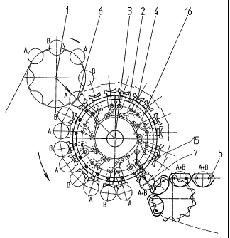
Fig. I A drum with incoming and outgoing means of transport in a
cross section;

Fig. 2 the drum according to Fig. 1 in a top view;

Fig. 3 the kinematic connection of every second tray carrier guided by
a radial cam.

The device presented in Fig. 1 comprises an incoming single-line means of
transport 1 with hollow bodies A and B. It comprises furthermore a rotary
driven drum 2 with a central hollow axis 3. On the drum 2, the individually
arriving hollow bodies A and B are accepted into transport trays 4 and
transported further. During further transport, they are changed in their
position so that all hollow bodies A or, respectively, B are transferred to a
second means of transport 5 to two parallel lines arranged side-by-side.

In the specified transfer points 6 or 7 respectively, the hollow bodies A and
B
are provided with the same transport speed as the first means of transport 1
or, respectively, the second means of transport 5. To this end, the drum 2
comprises swivable tubes 8 which serve to supply a vacuum. Spaced from
tubes 8, one parallel axis 9 each is arranged for the transport trays 4. The
transport trays 4 are replaceably arranged on intermediate slides 11. At the
intermediate slides 11, projections 12 are introducible in curved paths 13 of
the drum 2 for shifting the position of the hollow bodies in two parallel
lines. If
necessary, they can also be shifted into three or more parallel lines (not
shown). The embodiment presents two curved paths 13, 13' so that all hollow


CA 02599818 2007-08-31
bodies A are transferred in a first line and all hollow bodies B in a parallel
second line with the same axis (see Fig. 2).

On one first (right) side of the drum 2, the feed tubes 8 end in a control
disk
14 through which the supply of vacuum to the transport trays 4 can be
controlled to hold and fix the hollow bodies A, B during their transport
around
the drum 2.

On the opposite (left) side of drum 2, the swivable feed tubes 8 are in
contact
via swivel levers 15 with radial cams 16. This contact can be maintained by
springs 17, for example. The radial cams 16 effect that - in the transfer
point
6 - the corresponding transport tray 4 on drum 2 has the same speed as the
first means of transport 1, and in the transfer point 7, the same speed as the
second means of transport 5. Due to these speed adjustments effected via
the radial cams 16, smooth and safe transfers will be enabled.

Preferably, the transport trays 4 are exchangeable, e.g. provided by means
of plug-in connections on drum 2, whereby, without any tool, a simple
exchange of the transport trays 4 can enable an adjustment to different
diameter sizes of the hollow bodies A, B.

By means of the control disk 14, the consumption of vacuum will be
~_.
controlled and limited to the necessary minimum, with blowing out the
transport trays 4, if necessary, being possible in all transfer points 6, 7
for
trouble-free transfers.

The device is also more economical overall since it only requires one drive
for the continuous rotary movement of the drum 2 and, if necessary, of the
means of transport 1, 5 as well, or, respectively, it can be coupled with an
already existing drive (not shown) so that even the purchase costs will prove
to be significantly more economical.
Representative Drawing
A single figure which represents the drawing illustrating the invention.
Administrative Status

For a clearer understanding of the status of the application/patent presented on this page, the site Disclaimer , as well as the definitions for Patent , Administrative Status , Maintenance Fee  and Payment History  should be consulted.

Administrative Status

Title Date
Forecasted Issue Date Unavailable
(86) PCT Filing Date 2006-03-09
(87) PCT Publication Date 2006-09-14
(85) National Entry 2007-08-31
Examination Requested 2007-11-22
Dead Application 2011-03-09

Abandonment History

Abandonment Date Reason Reinstatement Date
2010-03-09 FAILURE TO PAY APPLICATION MAINTENANCE FEE
2010-04-13 R30(2) - Failure to Respond

Payment History

Fee Type Anniversary Year Due Date Amount Paid Paid Date
Application Fee $400.00 2007-08-31
Request for Examination $800.00 2007-11-22
Maintenance Fee - Application - New Act 2 2008-03-10 $100.00 2008-03-07
Maintenance Fee - Application - New Act 3 2009-03-09 $100.00 2009-02-20
Owners on Record

Note: Records showing the ownership history in alphabetical order.

Current Owners on Record
SPRIMAG SPRITZMASCHINENBAU GMBH & CO KG
Past Owners on Record
RAMMINGER, DIETMAR
Past Owners that do not appear in the "Owners on Record" listing will appear in other documentation within the application.
Documents

To view selected files, please enter reCAPTCHA code :


To view images, click a link in the Document Description column. To download the documents, select one or more checkboxes in the first column and then click the "Download Selected in PDF format (Zip Archive)" or the "Download Selected as Single PDF" button.

List of published and non-published patent-specific documents on the CPD .

If you have any difficulty accessing content, you can call the Client Service Centre at 1-866-997-1936 or send them an e-mail at CIPO Client Service Centre.


Document
Description 
Date
(yyyy-mm-dd) 
Number of pages   Size of Image (KB) 
Abstract 2007-08-31 1 27
Drawings 2007-08-31 3 88
Description 2007-08-31 3 129
Representative Drawing 2007-11-21 1 19
Cover Page 2007-11-21 2 64
Claims 2007-08-31 2 48
Claims 2007-09-01 2 52
PCT 2007-08-31 5 229
Assignment 2007-08-31 4 88
Prosecution-Amendment 2007-08-31 3 84
Correspondence 2007-11-16 1 29
Correspondence 2007-10-25 2 65
Correspondence 2007-11-28 1 31
Prosecution-Amendment 2007-11-22 2 53
Fees 2008-03-07 1 43
Fees 2009-02-20 1 44
Prosecution-Amendment 2009-10-13 3 126