Note: Descriptions are shown in the official language in which they were submitted.
CA 02599839 2007-08-31
WO 2006/092048 PCT/CA2006/000299
ELECTROMAGNETIC ACTUATOR
FIELD OF THE INVENTION
[0001] The present invention relates to actuators, more
particularly to electromagnetic actuators.
BACKGROUND OF THE INVENTION
[0002] Electromagnetic linear actuators of an inchworm
type are known and one common solution is achieved by
directly moving an actuator armature in small steps using
piezoelectric, electromagnetic, or magnetostrictive
armature translators. Such translators can move the
armature in nanometer increments, and can exert very large
forces, because they rely on the stiffness of an expanding
or contracting material. For example, electromagnetic
linear actuators of an inchworm type are disclosed in
United States patents 5,027,027 (Orbach et al.), 3,902,085
(Bizzigotti) and 3,902,084 (May, Jr.) The performance
efficiency of the actuators disclosed in those prior art
documents is limited due to' the limitation of the
structures thereof.
[0003] Improvements to the , field of electromagnetic
actuators are available, however.
SUNIIMARY OF THE INVENTION
[0004] The object of the present invention is to provide
an electromagnetic actuator.
[0005] In accordance with one aspect of the present
invention, there is provided an electromagnetic actuator
which comprises a first member and a second member moveable
relative to the first member. The second member includes
CA 02599839 2007-08-31
WO 2006/092048 PCT/CA2006/000299
- 2 -
first end, central and second end elements of a
magnetostrictive material, the elements being mounted one
to another in series with the central element disposed
between the first and second end elements. The second
member further includes means for forcing engagement of the
first and second end elements with the first member, and
means for selectively, magnetostrictively activating the
first end, central and second end elements in a controlled
manner for permitting the respective first and second end
elements to selectively, co-operatively release the forced
engagement thereof with the first member while permitting
controllably expanding and contracting the central element
in a longitudinal direction, thereby causing movement of
the first member relative to the second member.
[0006] In accordance with another aspect of the present
invention, there is provided an electromagnetic actuator
which comprises a first member and a second member moveable
relative to the first member. The second member includes
first end, central and second end elements of a
magnetostrictive material mounted one to another in series
and at least partially defining a passage for receiving the
first member extending therethrough. The central element is
disposed between the first and second end elements such
that magnetostrictive activation thereof changes the
distance between the first and second end elements. The
first and second end elements have respective restraining
members therearound restraining radial expansion thereof.
The first and second end elements is preloaded to apply a
clamping action on the first member, the clamping action
being releasable by magnetostrictive activation of the
first and second end elements. The second member further
includes an activation apparatus adapted to controllably
CA 02599839 2007-08-31
WO 2006/092048 PCT/CA2006/000299
- 3 -
magnetostrictively activate the first end, central and
second end elements according to a control sequence.
[0007] In accordance with a further aspect of the present
invention, there is a method of providing a motion between
first and second members, the second member including first
end, central and second end elements of a magnetostrictive
material, being mounted to one another in series with the
central element disposed between the first and second end
elements, the method comprising: (a) applying a pre-load
compression force through the elements while'restraining a
predetermined surface of the first and second end elements,
thereby engaging the first and second end elements with the
first member; (b) intermittently producing magnetic flux in
the respective first and second end elements to alternately
disengage and engage the first and second end elements from
and with the first member; (c) intermittently producing
magnetic flux in the central element to expand the central
element against the compression force and then contract
under the compression force, thereby moving one of the
first and second end elements reciprocally relative to the
other; and (d) controlling the timing of steps (b) and (c)
to allow said one of the first and second end elements
engaging the first member to move together with the first
member relative to the other, either in one direction under
a magnetostrictive force when the central element expands
orin the other.direction under the pre-load compression
force when the central element contracts.
[0008] The electromagnetic actuator of the present
invention advantageously has a very high force capacity in
addition to a very controllable action. The stroke length
CA 02599839 2007-08-31
WO 2006/092048 PCT/CA2006/000299
- 4 -
of a linear actuator embodiment of this device is only
limited by the length of the driven member.
[0009] Other features and advantages of the present
invention will be better understood with reference to the
invention described hereinafter.
BRIEF DESCRIPTION OF THE DRAWINGS
[0010] Reference will be now made to the accompanying
drawings in which:
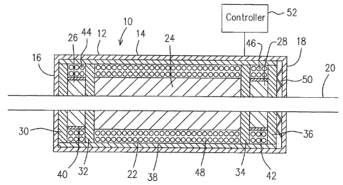
[0011] Fig. 1 is a cross-section of an electromagnetic
linear actuator according to one embodiment of the present
invention;
[0012] Figs. 2A-2C show a schematic illustration, showing
a sequence of operations of the embodiment of Fig. 1 in one
direction; and
[0013] Figs. 3A-3C are schematic illustrations, showing a
sequence of operations of the embodiment of Fig. 1 in the
other direction.
DETAILED DESCRIPTION OF THE PREFERRED EMBODIMENT
[0014] Referring to Fig. 1, an electromagnetic linear
actuator in accordance with one embodiment of the present
invention,generally indicated by numeral 10 includes a
base structure, preferably a housing 12 having a
cylindrical wall 14 axially extending between two opposed
end walls 16 and 18. The respective opposed end walls 16,
18 define central openings (not indicated) therein for
receiving an elongate driven member, preferably a non-
magnetic steel rod 20 extending therethrough, and
CA 02599839 2007-08-31
WO 2006/092048 PCT/CA2006/000299
- 5 -
permitting the rod 20 to axially move in either direction
relative to the housing 14. The rod 20 may not be
necessarily a rigid steel rod, but may be a section of a
flexible but not extendible cable, or other types, which
will be further described hereinafter.
[0015] A driver assembly 22 is operatively supported
within the housing 12 and includes central, first and
second end elements of a magnetostrictive material,
preferably-a central hollow cylinder 24, first and second
end hollow cylinders 26, 28. The magnetostrictive material
is preferably the compound Terfenol-D which possesses an
unusually large magnetostrictive strain. Under its pre-
stressed condition, magnetic field applied to a
magnetostrictive material will result in a large positive
magnetostrictive strain or expansive deforrnation of the
material.
[0016] The first end, central and second end hollow
cylinders 26, 24 and 28 are positioned in series, each of
the cylinc7.ers defining an inner passage (not indicated) for
receiving the rod 20 extending therethrough. Washers 30,
32, 34 and 36 are provided at the outer end of each of the
first and the second end hollow cylinders 26, 28, and
provided between the first end hollow cylinders 26 and the
central hollow cylinder 24, and between the central hollow
cylinder 24 and the second end hollow cylinder 28,
respectively. The washers 30, 32, 34 and 36 are made of a
magnetic flux permeable material, preferably
electromagnetic steel for guiding magnetic flux. A
cylinder 38 of a magnetic flux permeable material,
preferably electromagnetic steel, is provided within the
housing 12, containing the washers 30-36 and the hollow
CA 02599839 2007-08-31
PCT/CA2006/000299
03 January 2007 03-01-2007
- 6 -
cylinders 24-28 therein. The washers 30-36 have an inner
diameter to allow an axial movement thereof relative to the
rod 20, and an outer diameter to permit the washers 30-36
to axially move relatively to the steel cylinder 38 while
keeping in contact with the steel cylinder 38, thereby
forming a closed magnetic flux guiding circuit for each of
the first end, central and second end hollow cylinders 26,
24 and 28.
[0017] Each of the first and second end hollow cylinders
26, 28 is provided with a restraining ring 40 and 42 which
is tightly fitting on the outer periphery of the first and
second end hollow cylinders 26, 28 to restrain radial
expansion thereof. The restraining rings 40 and 42 are
made of non-magnetic metal, preferably made of titanium.
[0018] Electromagnetic circuits, such as first and second
excitation coils 44, 46 and main extension coil 48 are
provided within the steel cylinder 38 and around the first,
second end cylinders 26, 28 and the central hollow cylinder
24, respectively for producing magnetic flux in each of the
cylinders 26, 24 and 28.
[0019] Means for applying an axial compression force, for
example a dish plate spring 50 is provided between the
washer 36 and the end wall 18 of the housing 12 to urge the
entire driver assembly 22 towards and against the end wall
16 of the housing 12, thereby applying the axial
compression force through each of the cylinders 26, 24 and
28. Under this axial compression force, the central hollow
cylinder 24 radially expands both inwardly and outwardly.
The inner passage of the central hollow cylinder 24 has a
diameter such that under the radially expanding condition
AMENDED SHEET
CA 02599839 2007-08-31
WO 2006/092048 PCT/CA2006/000299
- 7 -
caused by the axial compression force, the central hollow
cylinder 24 maintains an axially moveable feature relative
to the rod 20. With the restraining rings 40 and 42, the
respective first and second end hol'low cylinders 26, 28 are
prevented from outwardly radially expanding when the axial
compression force is applied thereto, and the first and
second end hollow cylinders 26, 28 can only expand radially
and inwardly, thereby reducing the diameter of the inner
passage thereof. The inner passage of the respective first
and second end hollow cylinders 26, 28 is properly sized
such that a clamping action between the rod 20 and each of
the first and second end hollow cylinders 26, 28 occurs
when the axial compression force is applied by the spring
50, thereby the relative axial movement between the rod 20
and each of the first and second end hollow cylinders 26,
28 is prohibited. When electric current is introduc,ed to
the respective coils 44, 46, magnetic flux is produced in
the Terfenol-D of the respective hollow cylinders 26, 28,
resulting in a forceful axial expansion thereof against the
applied axial compression force by the spring 50.
Associated change in diameters of the respective hollow
cylinders 26, 28 also occurs, thereby releasing the
clamping action between each of the first and second end
hollow cylinders 26, 28, to allow the relative axial
movement between the rod 20 and each of the first and
second end hollow cylinders 26, 28.
[0020] It should be noted that under the axial compression
force applied by the spring 50, the first end hollow
cylinder 26 is restrained by the end wall 16 of the housing
12 while the axial position of the 'second end hollow
cylinder 28 relative to the first end hollow cylinder 26
and the housing 12 is variable. The distance between the
CA 02599839 2007-08-31
WO 2006/092048 PCT/CA2006/000299
- 8 -
first and second end hollow cylinders 26, 28 is determined
by the axial dimension of the central hollow cylinder 24.
Therefore activating and deactivating the central hollow
cylinder 24 by energizing and de-energizing the main
extension coil 48 which result in respective axial
expansion and contraction of the central hollow cylinder
24, move the second end hollow cylinder 28 in
reciprocation. Depending on which of the first and the
second end hollow cylinders 26, 28 is activated to release
the clamping action on the rod 20, the second end hollow
cylinders 28 will move with or without the rod 20. By
appropriate timing of the energizing and de-energizing of
the respective first and second excitation coils 44, 46 and
the main extension coil 48, an inchworm type of motion of
the rod 20 in either direction relative to the housing 12
can be achieved. The appropriate timing of the energizing
and de-energizing the respective coils 44, 46 and 48 is
controlled by a controller 52 which regulates the frequency
and the phase of AC current introduced to the individual
coils 44, 46 and 48.
[0021] Referring to figs. 2A-2C, a sequence of operations
of the.electromagnetic liner actuator 10, as an example, is
described. A first step of the operations is to activate
the second end hollow cylinder 28 to release the clamping
action between this cylinder and the rod 20 while
maintaining the deactivating condition of the first end
hollow cylinder 26 and the central hollow cylinder 24.
Thus, the first end hollow cylinder 26 clamps the rod 20
and the central hollow cylinder 24 maintains its axial
dimension under the axial compression force indicated by
arrow 54. At this moment the second end hollow cyli.nder 28
is urged by the axial compression force 54 towards the
CA 02599839 2007-08-31
WO 2006/092048 PCT/CA2006/000299
- 9 -
central hollow cylinder 24, and is maintained in its first
(the original) position indicated by line 56, as shown in
Fig. 2A. In the next step, the central hollow cylinder 24
is activated to axially expand. The central cylinder, 24
can only expand towards the second end hollow cylinder 28
and moves same against the axial compression force 54 to a
second position indicated by line 58, because at the other
end the central hollow cylinder 24 is restrained from
axially expanding by the first end hollow cylinder 26
abutting the end wall 16 of the housing. During the axial
motion of the second end hollow cylinder 28 from the first
position 56 to the second position 58, the rod 20 remains
still because the rod 20 is clamped by the stationary first
end hollow cylinder 26, but not the moving second end
hollow cylinder 28. When the second end hollow cylinder 28
reaches the second position 58, the second end hollow
cylinder 28 is deactivated and thereby clamps the rod 20,
as shown in Fig. 2B.
[0022] The first end cylinder 26 is activated to release
the clamping action thereof on the rod 20 and then the
central cylinder is deactivated to contract in its axial
dimension to the length as show in Fig. 2A. Thus the axial
compression force 54 urges the second end hollow cylinder
28 to return to its first position 56 as shown in Fig. 2C.
During the axial motion of the second end hollow cylinder
28 from the second position 58 to the first position 56,
the rod 20 is moved together with the second end hollow
cylinder 28 in the direction towards the left side as
indicated by the arrow 60 in Fig. 2C because of the
clamping action between the rod 20 and the second end
hollow cylinder 28 which is moving. Therefore, the rod 20
CA 02599839 2007-08-31
WO 2006/092048 PCT/CA2006/000299
- 10 -
as a driven member completes its first step of an inchworm
motion in the direction 60.
[0023] The first end hollow cylinder 26 is deactivated to
clamp the rod 20 and then the second end hollow cylinder 28
is activated to release the clamping action thereof of the
rod 20, as show in Fig. 2A. From now on, the above-
described steps are repeated in a controlled manner such
that the rod 20 is continuously moving in the inchworm type
motion in this direction indicated by arrow 60.
[0024] It should be noted that in this motion mode, the
rod is moved by the axial compression force 54 which is
applied by the spring 50 of Fig. 1. The spring dish plate
50 is adapted provides powerful compression force up to
several thousands PSI to overcome,.an axial load carried,by
the rod 20.
[0025] Referring to Figs. 3A-3C, a sequence of operations
of the electromagnetic linear actuator 10 is described in
another motion mode. The operation steps in Figs. 3A-3C
are similar to the operation steps in Figs. 2A-2C by
selectively activating and deactivating the respective
first end, central and second end hollow cylinders 26, 24
and 28 such that the central hollow cylinder 24 in
cooperation with the applied axial compression force 54
moves the second end hollow cylinder in reciprocation while
the respective first and second end cylinders 26, 28 are in
cooperation to allow the rod 20 to move together with the
second end hollow cylinder 28 in a selected direction.
[0026] However, in contrast to the operation steps
illustrated in Figs. 2A-2C, prior to activating the central
hollow cylinder 24 to cause its axial expansion, the first
CA 02599839 2007-08-31
WO 2006/092048 PCT/CA2006/000299
- 11 - end cylinder 26 is activated to release the clamping action
thereof on rod 20 while the second end hollow cylinder 28
remains in its deactivated condition to clamp the rod 20.
This clamping condition causes the rod 20 to move together
with the second end hollow cylinder 28 from its first
position 56 to the second position 58 when the second end
hollow cylinder 28 is urged by the expansion of the
activated central hollow cylinder 24. The direction of
such inchworm of the rod 20 is indicated by arrow 62 in
Fig. 3B, opposite to the direction of the inchworm motion
of rod 20 in Fig. 2C. When the deactivated central
cylinder 24 is contracting and the second end hollow
cylinder 28 is being urged by the axial compression force
54 to move from the second position 58 to the first
position 56, the stationary first end hollow cylinder 26 is
deactivated to clamp the rod 20 and the moving second end
hollow cylinder 28 is activated*to release the clamping
action thereof on the rod 20, 'thereby the rod 20 being
locked in its position relative to the linear actuator 10
and being not capable of moving back together with the
second end hollow cylinder by the axial compression force
54. The operational steps show in Figs. 3A-3C are repeated
to drive the rod 20 as the driven member in a continued
inchworm motion in the direction 62. In this motion mode,
the rod 20 is moved by the magnetostrictive force of the
central hollow cylinder 24 against the axial compression
force 54.
[0027] It should be noted that when the rod 20 instead of
the housing 12 is affixed to a stationary structure, the
housing 12 can move in either direction along rod 20 in
operation of the actuator 10.
CA 02599839 2007-08-31
WO 2006/092048 PCT/CA2006/000299
- 12 -
[0028] The magnetostrictive force can reach up to eight
thousand PSI for overcome the preload of the axial
compression force 54 and an axial workload carried by the
rod 20, if sufficient electric current is provided.
Similar clamping forces provided by the respective first
and second end hollow cylinders 26, 28 are also achievable.
The stroke length of this linear actuator 10 is limited
only by the length of the rod 20. Nevertheless, each step
of the inchworm motion of rod 20 is determined by the
change in the axial dimension of the central cylinder 24.
In order to provide a more effective inchworm motion of rod
20 the axial dimension of the central cylinder 24 is
preferably substantially greater than the axial dimension
of the respective first and second end hollow cylinders 26
and 28.. This is advantageous in contrast to the prior art
in which the central cylinder is affixed at the middle
thereof to a, stationary structure such that only a half of
the axial length thereof is involved in the axial dimension
changes in either direction during operation, which limits
the performance of the actuators. The electromagnetic
linear actuator 10 of the present invention also provides a
very fine and very rapid motion of the rod relative to the
housing because the respective first end, central and
second end hollow cylinders can be activated and
deactivated at several thousand times per second.
[0029] It should be noted that the driven member which is
described in the above embodiment as a steel rod, can
alternatively be any flexible but not extendible member,
such as a steel cable. For example, the driven member
could be a cable of a winch. In a further alternative
configuration, the driven member may be curved or even
circular if desired. Furthermore, rather than being
CA 02599839 2007-08-31
WO 2006/092048 PCT/CA2006/000299
- 13 -
constrained to grip the driven member by a radially inward
squeezing motion, the actuator may be configured to instead
expand radially outward (radially inward movement being
preferably restrained) to outwardly engage, and thus grip,
an externally positioned driven member - that is, the
skilled reader will appreciate that, instead of the rod-
like driven member described above, a hollow drum-like
driven member could surround expandable magnetostrictive
elements instead. In such a design, the gripping action of
the magnetostrictive elements is activated by magnetic flux
rather than a compression force, the means for applying the
compression force and the expansion restraining apparatus
are therefore not needed and the operation steps will
change accordingly.
[0030] It should also be noted that when the driven member
is attached to a stationary structure, the driving member
including the megnetostrictive elements can become a driven
member, which extends the present invention to even broader
applications.
[0031] Still further modifications to the above-described
embodiments of the present invention will be apparent to
those skilled in the art which do not depart from the
principles of the invention described. Therefore, the
foregoing description is intended to be exemplary rather
than limiting. The invention is intended to be limited
solely by the scope of the appended claims.