Note: Descriptions are shown in the official language in which they were submitted.
CA 02600009 2007-08-20
WO 2006/091398
PCT/US2006/004783
TITLE OF THE INVENTION
AN LED ASSEMBLY, AND A PROCESS FOR MANUFACTURING THE LED
ASSEMBLY
BACKGROUND OF THE INVENTION
FIELD OF THE INVENTION
100011 The present invention is directed to an LED (light emitting diode)
assembly and to a
method of manufacturing the LED assembly, and which is particularly adapted to
address
issues of color differences between different LEDs within the LED assembly.
DESCRIPTION OF THE BACKGROUND ART
[0002] Traditional light sources are most commonly either incandescent or gas
discharge.
Each has advantages and disadvantages. Although inexpensive to manufacture,
the
traditional incandescent bulb suffers from two disadvantages. First, most of
the input energy
of traditional lighting is wasted as heat or infrared (non-visible) light;
only a small amount of
the input energy is transferred to visible light. Second, the lifetime of the
incandescent bulb
is limited and when failure occurs it is catastrophic. Traditional fluorescent
bulbs have a
longer life, but have significant performance variations across a range of
temperatures. At
some colder temperatures fluorescent bulbs do not function at all. Halogen
light sources are a
slight improvement in efficiency and lifetime over incandescent light sources
for a marginal
increase in cost.
[0003] Traditional sources of lighting can produce exact colors by filtering.
The filtering
process takes white lighting and removes all the light except the required
light of the
specified color and therefore further reduces the efficiency of the light
source. Traditional
lighting also is broadcast in all directions from the source, which may not be
advantageous
when the goal is to illuminate a small object. Lastly, traditional lighting
has a non-linear
relationship between brightness and input current. This non-linearity makes it
difficult to dim
the light source easily.
[0004] LEDs overcome many of the disadvantages of traditional lighting because
of their
significantly longer lifetime, higher efficiency, and ability to direct the
light. The Mean Time
Between Failures (MTBF) of typical incandescent light sources is in the order
of 10,000
hours. The MTBF of LEDs is on the order of 1-10 million hours. Typically only
5% of the
input energy is transferred to visible light for an incandescent light.
Similarly, for LEDs
about 15% of the input energy is transferred to visible light. The ratio of
lumens of light
1
CA 02600009 2007-08-20
WO 2006/091398
PCT/US2006/004783
output divided by the watts of input energy is another way to look at the
efficiency.
Traditional lighting has about 17 lumens/watt, whereas LED based (white) light
sources are
about 35 lumens/watt. The efficiency improvement equates to lower power
consumption or
higher light output for similar applied power. Generally, an individual LED
produces a low
level of light output that is insufficient for usage as a light source.
Combining a number of
LEDs into an assembly or array allows the array to be a reliable and cost
effective
replacement for traditional light sources.
[0005] When designed and fabricated, an array of LEDs in an assembly can be
electrically
interconnected in parallel, in series, or any combination thereof.
Additionally, the LEDs in
the assembly can be a single base color or many different colors. By combining
several
different colors into one assembly, a wide range of specified colors can be
displayed by the
light engine. These LED light engine assemblies are gaining widespread usage
because of
their ability to reduce electrical usage, improve maintenance costs, and allow
dynamic,
custom color projection.
[0006] LED assemblies are also rapidly replacing light bulbs in the Human
Safety
marketplace. Human Safety applications might include traffic lights, safety
beacons on
towers, warning lights at rail crossings, emergency egress lighting, aircraft
runway lighting,
and many more applications. In these applications LED light sources are
gaining popularity
for two reasons: (1) the increased reliability of LEDs, and (2) the reduced
costs and
difficulty of the repair and maintenance functions.
[0007] At the present time LED based light engines are in operation for Human
Safety
Applications in hundreds of thousands locations throughout the world.
[0008] LED lighting is also beneficial in architectural and theatrical
applications. The
benefit lies not only with the ability to produce an exact and repeatable
light for changing
moods and emotions but also with the ability to produce these colors
dynamically and across
a large number of light sources. This practice has been available in
theatrical lighting for
many years in various forms with tremendous improvement in digital color on
demand in the
relatively recent past. For architecture, the practical use of color remains
limited largely due
to the cumbersome use of theatrical grade fixtures in architectural
applications. The promise
of LED lighting is the ability to accomplish dynamic color in a more useful
form factor and
in real time for both theater and architectural applications.
[0009] A typical LED assembly includes a number of LEDs installed into a
system, and
typically all of the LEDs are a single base color. The technology is
progressing and new
requirements are emerging for the production of a broad spectrum of colors
from
2
CA 02600009 2007-08-20
WO 2006/091398
PCT/US2006/004783
combinations of two, three, four or more base colors of LEDs. Many assemblies
under
development include several Red LEDs, several Green LEDs, and several Blue
LEDs.
Several LEDs are needed of each color, because a single LED does not provide
sufficient
light for a light engine. Different LED colors are needed so that the
different colors can be
combined to make a broad spectrum of custom lighting effects.
[0010] A generalized LED assembly 10 is shown in Figure 1. The LED assembly 10
includes an LED light source 11, which in turn includes individual LEDs 12 of
different
colors represented by the designators ¨ R (red), G (green), and B (blue). The
LED assembly
11 includes the LEDs 12 and a support and associated circuitry for driving the
LEDs. The
associated circuit and support includes an electronic carrier or printed
circuit board (not
shown) to mechanically hold the LEDs 12 and to provide electrical input to the
LEDs 12, a
power supply 13 to convert input power into a usable form for the LEDs 12,
control
electronics 14 to turn the LEDs 12 on and off appropriately, perform
algorithms on the
electronic signal and communicate with other equipment in a larger lighting
system, and a
lens or diffuser (not shown) to modify the light appearance from several small
point sources
to a look that is both pleasing to a human and functional for the product.
[0011] LED assemblies do, however, have the following disadvantages recognized
by the
present inventor. Variations within manufacturing of the optical and
electrical output
properties are sizeable. Targeted output colors are difficult to achieve
because of the
manufacturing variations of the LEDs. The optical output varies over the
product lifetime;
for instance, the output intensity degrades with time. The dominant wavelength
is highly
dependent on temperature. And, intensity drops with temperature increases.
[0012] Further, for LEDs different semiconductor compounds are used to produce
different
colors. Each compound will change at a different rate with respect to
temperature and long
term degradation. This has made the color stability of an array of ROB (Red,
Green, Blue)
LEDs difficult.
[0013] The fact that LED light output varies proportionately with input
current is generally
an advantage of LEDs; it becomes a disadvantage when an LED assembly is used
as a direct
replacement for an incandescent bulb. This is because the control system
compensates for the
non-linearity of the incandescent bulb and produces nonsensical output with
the replacement
LED assembly.
[0014] Lighting control systems or consoles address a limited number of light
outputs with a
limited number of possible color specifications and may require cumbersome
hardware to
address large lighting systems.
3
CA 02600009 2007-08-20
WO 2006/091398
PCT/US2006/004783
[0015] Temperature variations of the LEDs can occur for two reasons. One
source is the
outside environment. LED light sources can be installed in controlled
temperature
environments, examples of which would be home or office buildings.
Alternatively, they can
be installed in uncontrolled temperature environments where temperature
variations are in the
range of human habitability and beyond. The second source of temperature
variability is the
efficacy of the thermal dissipation within the specific system. Optical output
properties are
related to the die temperature. The die temperature is related to the outside
environment, but
also the thermal resistance of the entire path from the die to the outside
world.
[0016] The dominant wavelength (represented by Xd) and the optical intensity
exhibit
quantifiable changes with these temperature changes. With sufficient
temperature variations
the change in the dominant wavelength can be discernible by the human eye. At
some
wavelengths (near the color amber) changes of 2-3 nanometers (nm) are
discernible to the
human eye; at other wavelengths (near the color red) changes of 20-25 nm are
required before
the human eye can differentiate a color shift. The intensity change with
temperature is
discernible as well. Temperature increases of 60 C can reduce output by
approximately
50%.
[0017] The current state of the art partially addresses the issues. The
manufacturing
variation of the LED optical output is resolved by sorting or binning the LEDs
into groupings
of similar optical properties. The optical response of an incandescent light
has been
mimicked in the control software and hardware for the array, see for example
U.S. Patent
6,683,419. The initial power output of the LED can also be over-driven, which
results in
acceptable power outputs over a longer period of time.
[0018] The current state of the art, however, does not resolve the following
issues. Exact
color generation of a specified color is still not achievable. Binning of the
LEDs is not
always sufficient to produce an accurate color across all environments because
of the wide
variations in the LED optical properties within a bin. Temperature variations
effects on LED
output wavelength and intensity are not compensated for.
SUMMARY OF THE INVENTION
[0019] Accordingly, one object of the present invention is to provide a novel
LED assembly
and novel method of manufacturing the LED assembly that can efficiently and
consistently
provide a desired color output of the LED assembly.
4
CA 02600009 2013-03-12
[0020] A more specific object of the present invention is to provide a novel
LED assembly
and novel method of manufacturing the LED assembly that can compensate for
color
variations of individual LEDs within the LED assembly.
[0021] In accordance with an aspect of the present invention, there is
provided a
process for manufacturing a light emitting diode (LED) assembly including LEDs
of a
plurality of colors, comprising:
(a) driving all LEDs of a first color and measuring information of an optical
output of the driven LEDs;
(b) measuring a first environmental condition while the driving all the LEDs;
(c) storing in a memory in the LED assembly the measured first environmental
condition and the measured information of optical output; and
(d) repeating the driving (a) and measuring (b) and storing (c) for the LEDs
of
each of the plurality of colors.
[0022] In accordance with another aspect of the present invention, there is
provided a
light emitting diode (LED) assembly comprising:
(a) a plurality of sets of LEDs of a plurality of colors, each set of LEDs
including LEDs of only one specific color of the plurality of colors;
(b) control electronics configured to control driving of the plurality of
LEDs,
the control electronics including a memory storing measured information of
optical
outputs for each set of LEDs at at least one environmental condition measured
while
the driving of the pluralities of LEDs.
BRIEF DESCRIPTION OF THE DRAWINGS
[0023] A more complete appreciation of the present invention and many of the
attendant
advantages thereof will be readily obtained as the same becomes better
understood by
reference to the following detailed description when considered in connection
with the
accompanying drawings, wherein:
[0024] Figure 1 shows a generalized background LED light assembly;
[0025] Figure 2 explains LED color specifications on a CIE chromaticity chart;
CA 02600009 2013-03-12
[0026] Figures 3a and 3b show processes for uncompensated optical output of an
LED
assembly;
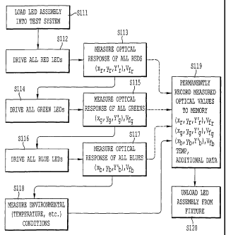
[00271 Figure 4 shows a process flow of operations conducted in a method of
manufacturing
an LED assembly according to the present invention;
[0028] Figure 5 shows a simplified pictorial of a manufacturing fixture
utilized in a method
of manufacturing the LED of the present invention;
[0029] Figures 6a, 6b show an overview of processes for realizing a
compensated optical
output for an LED assembly of the present invention;
5a
CA 02600009 2007-08-20
WO 2006/091398 PCT/US2006/004783
[0030] Figure 7 shows an LED light engine assembly of a first embodiment of
the present
invention; and
[0031] Figure 8 shows a more generalized operation of processes performed in
manufacturing an LED assembly according to the present invention.
DESCRIPTION OF THE PREFERRED EMBODIMENTS
[0032] Referring now to the drawings, wherein like reference numerals
designate identical or
corresponding parts throughout the several views, features of the present
invention are
detailed.
[0033] Color output can be specified using the CIE Color Coordinate System.
Other
appropriate schemes for specifying color can also be utilized. CIE is an
abbreviation for
"The Commission Internationale de l'Eclairage" and is an international
standards
development group that first described ways of quantifying color in a standard
written in
1931. The CIE Color Coordinate System is an accepted standard for the
measurement of a
spectral distribution and defines a color using an x coordinate, a y
coordinate, and a Y'
coordinate. The CIE Color Coordinate System is a device independent way of
describing
color and is therefore also described as a universal coordinate system for
defining colors, and
is shown graphically in Figure 2. Figure 2 shows the CIE Chromaticity Chart
with the CIE
Color tongue. The CIE Color tongue shows the x, y, and Y' coordinates for
saturated colors.
The x coordinate and the y coordinates are normalized and are represented on a
scale of 0 to
1. Both x and y coordinates are unitless and specify the color. Y' specifies
the intensity and
is normalized to a unitless number as welt
[0034] Typical Red, Green, and Blue LED color outputs are shown in Figure 2.
By
interconnecting coordinates representing Red, Green, and Blue, a triangle is
created. The CIE
coordinates within this triangle represent the range of available colors for
display. Points
outside of the triangle can not be displayed with the given light sources. The
center point of
the triangle is the CIE coordinate of the max combination of the Red, Green,
and Blue light
sources and is theoretically White.
[0035] The manufacturing process for the production of LEDs is inconsistent
and produces
LEDs with a large variability in their output. This variability is shown for
Red, Green, and
Blue graphically by the span of the ovals (16), (17), and (18) respectively.
Figure 2 also
identifies a Target White (15) and shows an additional oval (19) that
represents the range of
displayed White for combinations of the three color light sources of Red (16),
Green (17),
and Blue (18).
6
CA 02600009 2007-08-20
WO 2006/091398
PCT/US2006/004783
[0036] Figure 2 shows the white range (19) of the displayed color without
compensation for
the many sources of variability of the LEDs. This variability of the
individual LEDs includes
degradation in output intensity over the LED lifetime, changes in dominant
wavelength with
temperature, changes in output intensity with temperature, variability within
the
manufacturing process, and more.
[0037] Figure 3a is a simplistic or uncompensated process for producing white
light from the
output of Red, Green, and Blue LEDs. The process shown in Figure 3 includes
three
simultaneous steps S61, S62, and S63 in which respectively a maximum output of
all of the
red LEDs, a maximum output of all the green LEDs, and a maximum output of all
the blue
LEDs are generated. By performing those steps driving each of the Red, Green,
and Blue
LEDs to their maximum output, a maximum color output of the Red, Green, and
Blue LEDs
is generated in step S64 giving a theoretical white light output. That is,
maximally mixing
the Red, Green, and Blue, LEDs should provide a white light. However, because
of
differences between color outputs of individual of the LEDs, such a system has
a drawback in
that the variations in the color outputs of the Red, Green, and Blue LEDs may
not result in a
pure white output. The variability of the output from the process of Figure 3a
is shown on
the CIE Chromaticity Chart in Figure 2 as (19) and may be sufficient to cause
a measurable
difference of the white light from a theoretical white. The difference may be
discernible by
the human eye. The additive process of Figure 3a does not compensate for LED
variability
and may produce an inexact white. In addition to being inaccurate the result
is inconsistent.
[0038] Figure 3b is a similar simplistic or uncompensated process to produce a
custom color.
In the process of Figure 3b, initially each of the Red, Green, and Blue LEDs
are each driven
at their maximum output in steps S61, S62, S63, as in Figure 3a. Then, a
scaling is
introduced to each of those outputs to produce a desired color. More
specifically, step S71
adjusts Red LEDs drive parameters to obtain a desired Red light output, step
S72 adjusts
Green LEDs drive parameters to obtain a desired Green light output, and step
573 adjusts
Blue LEDs drive parameters to achieve a desired Blue light output. Each of
steps S71, S72,
and S73 can achieve the desired scaling by modifying drive parameters such as
duty cycle
and drive current for each of the respective Red, Green, and Blue LED outputs.
The
combined output is, ideally, the desired custom color. Unfortunately this
simplistic process
may also yield unacceptable results. LED variability at each of the three
input stimuli
induced by a number of factors may yield an inaccurate and inconsistent
representation of the
target color.
7
CA 02600009 2007-08-20
WO 2006/091398 PCT/US2006/004783
[0039] Single color LED light engine assemblies have been in production for a
number of
years. The variability associated with the fabrication of single color LEDs
and the precise
requirements of the Human Safety marketplace, where they have chiefly been
implemented,
have challenged the LED assembler to produce an accurate output color for the
entire system.
The LED manufacturers have assisted the assemblers by pre-sorting or binning
the LEDs into
smaller ranges of variability prior to shipment. The smaller range of LED
input stimuli has
assisted the assembler in producing a target output color. Acceptable color
rendering is still a
demanding task because even the bins have a sizeable range of the performance
variations.
[0040] The binning operation can become complex quite quickly. An assembly
with only
Amber LEDs shall be used as an example. The Amber LED arrives from the
manufacturer
sorted by five flux values which may be identified with the labels V, W, X, Y,
and Z. The
variation across each flux bin can be 15% or more. The dominant wave length
may vary
2.5 nm and may be broken into five bins labeled 1, 2, 3, 4, and 5. Five
additional bins are
created based on Forward Voltage (Vf) values varying 5% and labeled a, b, c,
d, and e. The
result of all this sorting is that the Amber LEDs arrive at the assembler
sorted into 5*5*5 or
125 possible bin locations. A bin of Amber LEDs might be labeled as a W4e; W
specifying
its flux range, 4 specifying its dominant wavelength, and an e specifying its
Forward Voltage.
[0041] The LED assemblies can be fabricated using recipes of LEDs from the
different bins
of Amber LEDs. Each recipe contains the acceptable bin code or bin codes for
each LED
location within the electronic carrier of the LED light engine assembly
design. Acceptable
recipes are engineered prior to fabrication to an output that is acceptable to
the customer's
required optical parameters. The acceptable recipes are determined using
optical
performance calculations and verified experimentally. With a large number of
LEDs in the
assembly and a large variation of the optical output within a bin, it becomes
increasingly
difficult to assure the optical output of the entire assembly is acceptable to
the customer ¨
even with a recipe.
[0042] There are generally a number of acceptable recipes for each product.
Having a
number of recipes allows the assembler the flexibility to build the assembly
in several
different ways to account for inventory variations of the different bins of
LEDs. However,
even with a number of acceptable recipes for each product design, inventory
management of
the bin contents in high volume production can be a challenge to the
assembler. Conversely,
it is sometimes a challenge to find an acceptable recipe of LED bins with an
existing
inventory of bin quantities.
8
CA 02600009 2007-08-20
WO 2006/091398 PCT/US2006/004783
[0043] The above example used a simple LED assembly with only one color LED.
The
complexity of the recipes increases multifold when a design involves several
different color
LEDs and the recipes involve pulling LEDs from bins of several different base
colors. In
reality, multiple color LED light engine assemblies have been marginally
successful. The
accuracy issue of a single color becomes multiplied into a larger problem; the
end result may
be unacceptable color rendering. In summary, binning has allowed volume
production of
acceptable single color LED light engine assemblies. However, binning for
single color
assemblies lacks flexibility for manufacturing and can produce light output
outside the range
of acceptability. Binning becomes difficult or impossible to manage in
multiple color LED
assemblies and the resulting product is generally unacceptable.
[0044] The process of the present invention addresses such drawbacks by
measuring a
baseline optical performance of each unique, individual LED light engine
assembly at the
time of manufacture to quantify the exact color and intensity of the output,
as discussed in
further detail below. The quantified values of the baseline measurement of the
color are then
stored within the LED assembly and available to the system for compensation to
the driving
input parameters to produce an accurate and repeatable output throughout the
life of the
system.
[0045] The present inventor developed a process shown in Figure 4 that uses a
test system 40
of Figure 5. The process of Figure 4 is performed after assembly of all LEDs
and other
control electronics but prior to shipment at the manufacturing facility.
[0046] In the process each individual LED assembly 100 is loaded onto a
manufacturing test
system 40 (see Figure 5) at the beginning of the process, step S111 (see
Figure 4). The test
system 40 includes a holder 42 for constraining the LED assembly 100 a fixed
distance, d,
from an optical measurement instrument 45. A shield 44 directs the light, and
prevents stray
light entry to the optical measurement instrument 45.
[0047] The test system 40 also includes control electronics as well. The
control electronics
are divided between a customized interface box 41 and the internal circuitry
of a customized
computer or workstation 46. The test system 40 control electronics include a
measurement
device for measuring the current temperature, a control device for controlling
the LEDs, a
measurement device for measuring voltage, and a device for writing data to a
memory of the
LED assembly, which can be accommodated in the interface box 41, the
workstation 46, or
on control electronics internal to the LED assembly 100.
[0048] After loading the LED assembly 100 into the test system 40, the process
directs the
control circuitry to drive all of the Red LEDs and only the Red LEDs, step
S112. The control
9
CA 02600009 2007-08-20
WO 2006/091398
PCT/US2006/004783
circuitry for this process can either be internal to the LED assembly 100 or
internal to the test
system controller workstation 46. The allRed output is then measured in step
S113 with the
optical measurement device 45, which for example may include a
spectrophotometer. The
CIE coordinates for the allRed output and the forward voltage at the allRed
are measured in
step S113. Step S114 is similar to step S112 except that only all the Green
LEDs are driven
by the control circuitry. The CIE coordinates of the output for allGreen and
the forward
voltage for allGreen are measured in step S115 by the optical measurement
device 45.
Process step S116 is also similar to step S112 except that only all the Blue
LEDs are driven
by the control circuitry. Step S117 measures the allBlue optical output and
the allBlue
forward voltage. The steps S112, S114, and S116 may be easiest to implement if
all the Red,
Green, and Blue LEDs are driven at 100% maximum input condition. However,
because
LED flux output is mathematically related to its input current, the processes
could be
implemented with proportionately lower inputs. All optical measurements are
preferably
taken after the system has reached a steady state. Alternatively, a varying
pulse width can be
utilized to drive the LEDs and steady state output performance can be
extrapolated from
there. Steps S113, S115, and S117 could be implemented with any appropriated
Color
Coordinate System as described below.
[0049] Temperature and/or other relevant environmental data are then measured
in step S118
using a temperature measurement device 47. The environmental data is measured
to indicate
the environmental conditions which result in the measured outputs of the LEDs.
For
example, LED output will vary based on temperature, so it is relevant to know
for the
measured optical outputs of the Red, Green, and Blue LEDs in steps S113, S115,
and S117
what the temperature is at the time of measurement. The environmental
measurement of step
S118 is then used in a compensation algorithm 24 to control driving of the
LEDs, as
discussed below with reference to Figure 6. The algorithm accommodates the
optical output
change resulting from intensity changes and dominant wavelength changes with
temperature.
Future changes away from the baseline environment can be corrected by the
below discussed
compensation algorithm 24.
[0050] All of the measured information is then stored internal to the LED
assembly 100 in
step S119. The stored information is represented by the following variables
described below,
using CIE values (x, y, Y), Vf for forward voltage, and T for temperature.
[0051] (xõyõ.11;.) V fr (Xg,) g,17;)Vfg (rb,yb,Y)V , T
CA 02600009 2007-08-20
WO 2006/091398
PCT/US2006/004783
[0052] All of the stored information can be written in step S119 as described
or alternatively
the stored information could be written to a memory device of the LED assembly
immediately after they are acquired in steps S113, S115, and S117. This
alternative is shown
by the dashed lines in Figure 4.
[0053] Additional information about the performance of the unique light engine
"as
manufactured" can be stored internal to the system in step S119, e.g.,
possibly the date and
time of the measurements or the serial number of the product. Storage of these
initial
measurements external to the system can also be performed. Duplicate data
external to the
LED assembly could be used in the repair or rework of an assembly or utilized
for statistical
analysis of the production variability. The process completes in step S120 by
unloading the
LED assembly 100 from the test system 100 and proceeding with usage of the LED
light
engine assembly 100.
[0054] With the above process, the present invention characterizes and records
the LED
assembly's specific light output information at the time of manufacture to
record baseline
color output of the LED assembly, which information is then used in an overall
process of
generating compensated light output in an LED assembly in Figures 6 and 7. By
so doing, an
exact baseline of the displayed color can be made available to algorithms for
color
optimization.
[0055] Figures 6a and 6b and 7 show an LED assembly of the present invention
which stores
the data generated by the process in Figure 4, and which utilizes such data to
generate an
enhanced desired light output of the proper color. Figure 7 shows a structure
of an LED
assembly 100 including LEDs 105 in LED light 101 and power supply 103, in the
present
invention, and Figures 6a and 6b show control operations performed in that LED
assembly
100.
[0056] As shown in Figure 7, the LED assembly 100 of the present invention is
similar to
that in the background art of Figure 1, except the LED assembly 100 of the
present invention
includes enhanced control electronics 104 including an environmental sensor
106 and
memory 109. The memory 109 stores the data noted in step S119 in Figure 4.
[0057] There are many ways that the information can be stored in the system,
but one feature
is that the "as manufactured" output information remains available to the
optimization
algorithms throughout the life of the light engine. The internal method of
storing the
information can be any of a number of memory devices. A Read Only Memory
(ROM), a
Programmable Read Only Memory (PROM), an Erasable Programmable Read Only
Memory
11
CA 02600009 2007-08-20
WO 2006/091398
PCT/US2006/004783
(EPROM), an EEPROM (an Electrically Erasable Programmable Read Only Memory), a
Flash EPROMs, etc. can be used, as the memory 109.
[0058] The control electronics 104 in Figure 7 performs the operation shown in
Figures 6a,
6b, as now discussed in further detail below.
[0059] A first embodiment of the overall control operation of the LED assembly
100 of the
present invention as shown in Figure 6a is to utilize the stored baseline
light output data of
the Red LEDs, Green LEDs, and Blue LEDs that form the LED light 101 in
conjunction with
the stored environmental data, perform compensations based on the measured
output of those
lights and based on measured environmental values, and to output a desired
light output.
[0060] In the operation, stored values for the allRed response, allGreen
response, and allBlue
response are retrieved in processes 21-23. Those values correspond to the
values stored in
step S119 in Figure 4. That retrieved information in processes 21-23 can be
utilized by
compensation and color mixing algorithms to allow a custom color generation to
be realized.
[0061] More specifically, the retrieved stored values from processes 21-23 are
provided to a
process 24 that runs a compensation algorithm to predict an output under
current
environmental conditions based on the retrieved stored values. An output from
that
compensation algorithm 24 is then provided to a color mixing algorithm 25. The
color
mixing algorithm 25 receives as an input a desired light output from a process
30. Thereby,
the color mixing algorithm 25 receives an indication as to a desired light
output and can
modify the color mixing to achieve that desired light output. The color mixing
algorithm 25
then controls driving of parameters for the Red LEDs, Green LEDs, and Blue
LEDs in
processes 31-33 to output light of a desired specification in process 34.
[0062] The compensation algorithm 24 and color mixing algorithm 25 are the
control
algorithms to achieve a desired color output and are either hard programmed
with electronic
circuitry or soft programmed with custom software internal to the control
electronics 104 of
the LED light engine assembly 100. The color mixing algorithm 25 adjusts the
duty cycle
(D) and other parameters of each LED in processes 31-33, effectively modifying
the
percentages of each base color to customize the color display. The duty cycle
can be adjusted
using any number of control techniques ¨ including Pulse Frequency Modulation,
Pulse
Position Modulation, Amplitude Modulation, Phase Shift Modulation, and Pulse
Width
Modulation (see e.g., U.S. patent 6,016,038 to Color Kinetics).
[0063] Operating the compensation algorithm 24 and color mixing algorithm 25
in
combination with retrieving the stored optical parameters in processes 21, 22,
and 23 resolves
many of the performance issues of LED light engine assemblies. The
compensation
12
CA 02600009 2007-08-20
WO 2006/091398
PCT/US2006/004783
algorithm 24 can be applied to account for temperature variations in the
optical output.
Similarly, the lifetime degradation of LEDs can be overcome algorithmically in
the
compensation algorithm 24. That is, the compensation algorithm 24 can consider
current
environmental conditions, aging of the LED, etc., and can compensate the light
output of the
LEDs for such current conditions. For example light output of LEDs drops with
temperature.
Therefore, if the current temperature at the LED assembly 100 is higher than
when the LEDs
were tested, i.e., higher than the temperature stored in step S119 in Figure
4, then the
compensation algorithm 24 can control to increase the driving power of each of
the LEDs to
compensate for the decreased intensity resulting from the increased
temperature. Similarly,
the compensation algorithm 24 can factor the age of the LEDs and increase the
driving
current (I) to the LEDs 105 as the LEDs 105 age. The compensation algorithm 24
can
perform other compensations based on other environmental conditions, for
example
humidity, and other factors as needed.
[0064] Further, difficulties of recipes and binning can be accommodated by
appropriate
application of the color mixing algorithm 25. The compensation algorithm 24
and color
mixing algorithm 25 can provide for calculations of the compensated light
rendering process
because of an accurate known starting point. That is accomplished in the
process of the
present invention.
[0065] A specific non-limiting example of specifics of color mixing algorithm
25 that can be
implemented in the present invention is as follows.
[0066] The color mixing algorithm 25 begins with the target color specified
for display.
Targeted Color Coordinates 'Y1 , Y;')
(151)
[0067] The CIE Chromaticity coordinates (x, y , y') of the spectral input for
allRed,
allGreen, and allBlue are also known to the algorithm, see steps S113, S115,
S117 in Figure
4.
Measured (xõyr,17;.) , (xg,yg,Y;) , (xbolb,12) (152)
[0068] The desired output is the duty cycle of the allRed, allGreen, and
allBlue LED
assemblies for display of the target color and the driving current.
Find (yr D , ) and I (153)
g, b,
13
CA 02600009 2007-08-20
WO 2006/091398 PCT/US2006/004783
[0069] The derivation and details for a non-limiting implementation of the
color mixing
algorithm 25 is as follows.
[0070] First, z need not be given for any of the colors because of the
following defining
equation.
x+y+z=1
(154)
z =1¨ x ¨ y
[0071] Linear proportionality constants (weighting factors) for the
relationship between the
output intensity and y coordinate for allRed, allGreen, and allBlue are
calculated.
mr 07; /Yr)
(155)
mg = (Ydyg
mb /Jib)
[0072] The proportionality constants are used to calculate the CIE coordinates
of the
combination of allRed, allGreen, and allBlue ¨ ideally a true white color.
xrm,. + XgMg
xw = __________________________________________
Mr + Mg + Mb
(156)
Yrm, Ygmg Y17112b
=
mr + mg + mb
= Y,: +
[0073] CIE coordinates are converted to Tristimulus values. Tristimulus values
are a similar
coordinate system for describing the color that is not normalized. The
relationship between
the 2 coordinate systems is defined by the following equations (157).
Y=Y' x=_KAX+Y+Z) y=YAX+Y+Z) z=ZAX+Y+Z)
(157)
[0074] The following general equations can be quickly derived from equations
(154) and
(157) above.
X x Z z Z (1¨x¨y)
(158)
Y y Y y Y
14
CA 02600009 2007-08-20
WO 2006/091398 PCT/US2006/004783
[0075] The general equations (158) above create the specific equations for the
Tristimulus
values X, Y, Z for allGreen, allRed, allBlue and the resultant white shown as
equations
(159). It is important to note that this white may not necessarily appear
white. The degree to
which it is truly white will depend on how evenly balanced the 3 stimulus
colors are around
the center coordinates of white (0.333, 0.333, 0.333).
xr Y;(1¨ x
x __________________________ y y' z r r
r
Y r Y r
X
(1¨x ¨Y )17.'
X = ____________________ gg Y =17' Z g g g
g Y g g g g Yg
(159)
vb.x b b v. v' 7 ___________________________________
di yb 2b -Lb 'b
Yb
X Y'(1¨
.X ¨ ' Y ¨ Z ¨ "
w ¨ w ¨ w w
Yw
[0076] The same equations can be used to convert the given CIE values of the
target color to
(xõ yõ Yg) to Tristimulus values of (X, , Y, z,) as below.
x,Y; (1¨x1 ¨y )1?
y 7 = t t (160)
--t -I t
Yt Y t
[0077] Scale Factors (SõSg,Sb) are required for the transformation matrix M
and are
calculated from the known values on the right hand side of equation (160) as
follows.
--1
Xr Yr Zr (161)
[S, Sg Sh I= {xw Yw w] X g Yg Zg
X b Yb Zb
SrX r Sri'; SrZr
[Ad] SgXg S g Yg gg S Z
_SbXb SbYb SbZb _
(162)
[0078] The [R, G, B1] for the target color is the amount of Red, Green, and
Blue in the
target color and could be used to describe the color if an RGB specification
system were
utilized as follows.
CA 02600009 2007-08-20
WO 2006/091398 PCT/US2006/004783
[R, G, B ,1=[X Y, Zt] [M]'
(163)
[0079] The duty cycle, D, of each of the colors is calculated below. For ease
of
implementation, one of the three duty cycles for allRed, allBlue, or allGreen
is always
defined as 100%. The other two duty cycles are scaled to keep similar ROB
proportions.
Dr =R,/max(RõGõB,) Dg =G, imax(RõGõ B, ) Dbt=B, imax(RõGõ B, )
(164)
[0080] Further simplifying for the instance when [S,,SpSd= [1.0, 1.0, 1.01,
the instance is
relevant when the design requirements state that the combination of allRed,
allGreen, and
allBlue does not have to be a pure white.
C = X (yg ¨ yr )+ xg (yr ¨ yb )+ xr (yb ¨ yg
R Yr kb (YI )+ xt (Yg Yb )tA
, =
y, = Yr= = c
G g
Y (Y: JO+ xt (Yr Yb)+ xr (Yb
t =
y, = 17; = C
B Yb[Xt(Yg Yr)+ Xg(Yr Yt)+ Xr(Yt ¨
, =
Yt'171,'
Dri= R,/max(RõGõBr) Dg = G, /max (RõGõBg) Dbt B, /max (RõGõ.8,)
[0081] The present equations have only related to the generation of the color
and not to the
intensity of the color. The target color intensity is expressed by .
Adjustments for
intensity are calculated as follows:
Ytoi tat =Y; -EY; +
[0082] 'ref is the driving current specified by the LED manufacturer and used
in the
manufacturing testing process to generate the stored values for processes 21,
22, and 23 of
Figure 6.
Case 1: If Y
tal .17,' then the following equations apply. The duty cycles
are
downscaled appropriately to account for the intensity.
16
CA 02600009 2007-08-20
WO 2006/091398 PCT/US2006/004783
Yt' n
D'=
r ¨ r
t yr
total I
171' n
D' =
lit
total gt
Yt
D'= 1 D
111 y;of tai 61
'tested
Case 2: If Y;01 tai <17 then the following equations apply. The driving
current is
upscaled appropriately to accommodate the additional required brightness.
D' =Dr
t
D' =D
gt gt
= D b
Yti
I = __ Itested
Ytotal
[0083] The targeted color is therefore displayed for both case 1 and case 2
using the duty
cycles (D; , Dg' , D ) and the driving current I.
[0084] Figure 6b shows a modification of the embodiment of Figure 6a, which
can be
applied to a device including different colored LEDs of Red LEDs, Blue LEDs,
Green LEDs,
and Amber LEDs. That is, instead of having a system with only three colors of
Red, Blue,
and Green, a system can incorporate four colors of Red, Blue, Green, and
Amber. In those
circumstances the operations shown in Figures 3a, 3b, and 4 will also perform
operations
directed to the Amber LEDs similarly as for the Red, Green, and Blue LEDs. As
a result,
measured optical values stored in memory will also include data for the Amber
LEDs, and
thus in Figure 6b an additional operation of retrieving the all Amber response
in process 26 is
executed, and then in process 34 the duty cycle and other parameters of the
Amber LEDs are
also adjusted similarly as for the Red, Green, and Blue LEDs.
[0085] The present invention is not even limited to such an embodiment with
four colors, but
any number and colors can be used in any desired combination.
[0086] A previous example assembly is now used for the discussion on the
present
invention. Assume a previous assembly includes several Red LEDS, several Green
LEDs,
and several Blue LEDs. Additionally, for ease of explanation the combined
output from all
Red LEDs shall be referred to as the allRed Output. If there is only one Red
LED then the
17
CA 02600009 2007-08-20
WO 2006/091398
PCT/US2006/004783
output of the Red LED and allRed will be equal. Similarly, the display of all
Green LEDs
shall be referred to as allGreen and all Blue LEDs as allBlue.
[0087] The process of the present invention allows the generation of an exact,
known,
starting point or baseline of the color output and internal storage of that
known starting point
within the system. The light output of a specific LED assembly is initially
stored internal to
the assembly on an appropriate memory device. This initial point can be
utilized by an
appropriate compensation algorithm 24 and an appropriate color mixing
algorithm 25 at any
later point in time to produce a desired color match.
[0088] The process of the present invention involves storing the specific
light output
description internal to the LED light engine assembly, by the process of
Figure 4, which is
then used for custom color rendering. Then, in operation of the LED assembly
100 the stored
data are retrieved in processes 21, 22, and 23 of the compensated light
process of Figure 6.
By so doing, an exact baseline of the displayed color can be made available to
the
compensation algorithm 24 and color mixing algorithm 25. The processes S113,
S115 and
S117 of Figure 4 generate the CIE coordinates of allRed, allGreen and allBlue,
and the
processes 21, 22 and 23 of Figure 6 utilize the CIE coordinates of allRed,
allGreen and
allBlue.
[0089] The allocated memory 109 for storing the initial optical performance
information can
be a dedicated single component. Alternatively, the information can be
combined with other
system information and added to the storage components that already reside in
the system.
For instance, the stored output of the manufacturing process of the present
invention could be
added to the firmware of the control system and stored on the same physical
device as the
firmware.
[0090] Color specifications in the process of Figure 4 can be transmitted
using the CIE Color
Coordinate System. There are other universal color coordinate systems that are
device
independent that could also be utilized to quantify the light source. The Lab
Model uses
Lightness (L), an (a) coordinate along a green to red spectrum, and (b)
coordinate along a
blue to yellow spectrum. The Munsell Color System uses three coordinates of
Hue (H),
Value (V), and Chroma (C). The present invention does not exclude the usage of
any of these
universal color coordinate systems, but that the CIE System is believed to be
the most
effective at communicating an exact color.
[0091] If another coordinate system is used then the measured and stored
values would not
be exactly the variables listed below
18
CA 02600009 2007-08-20
WO 2006/091398
PCT/US2006/004783
[0092] (Xõ yõ Y; V1 , ccg, yg, 1,74 , (xoyb,Y:)Tibb , T
[0093] Conceptually, they would be similar values describing the color but in
a new
coordinate system. For instance for an Lab Model they would most likely be
[0094] (Lõaõbr)Vf, , (Lg,ag,bb)V4, , (Lb,ab,bb)Vb, , T
[0095] And for the Munsell System they might be
[0096] , Võ ) Vfr, (.1 Vg Cg 18 b, Vb,Cb) Vbb T
[0097] There are a number of different Color Coordinate System standards based
around the
3 colors of Red, Green, and Blue. Examples of standard RGB color spaces
include ISO
RGB, sRGB, ROMM RGB, Adobe RGB, Apple RGB, and video RBG spaces (NTSC, EBU,
ITU-R BT.709). But none of these standards are universal, and there may never
be a
universal RGB standard because the needs of different applications (scanners,
digital
cameras, monitors, printers) are different. There are also CMYK color
standards based on
proportions of Cyan, Magenta, Yellow, and Black. The CMYK standards suffer
from the
same lack of universality disadvantage as the ROB standards. Any of these
standards could
be used for the color description of the present invention, but the CIE Color
Coordinate
System may be the preferred implementation because of its more universal
acceptance.
[0098] The process described above with respect to Figure 4 shows obtaining
data for a
system with up to three colors, and Figure 6b shows application for a system
with up to four
colors. There is no requirement that the system include only these colors but
any number of
colors can be incorporated. A more generalized process that can be performed
in the present
invention is shown in Figure 8, which essentially achieves the same results as
the process of
Figure 4, but which can be applied to as many colors as desired with different
environmental
conditions.
[0099] The more generalized process of Figure 8 has the same goal as the
process of Figure
4. Step S131 begins the generalized process by loading the LED light engine
assembly 100
into the test system 40. Step S132 is the beginning of an "outer loop"
iteration function
designed to quantify the relevant, baseline optical properties across a number
of
environments. If only one environment is baselined as in the specific example
above, then
=
the number of environments is one and the iteration loop is only performed
once. The
environments can either be controlled, as in a thermal and humidity test
chamber, or
uncontrolled, as the LED die temperature at the time of manufacture. Relevant
19
CA 02600009 2007-08-20
WO 2006/091398 PCT/US2006/004783
environmental variations might be temperature, humidity, system "on time",
altitude, or any
other environmental condition. Step S133 quantifies the relevant environmental
condition
either using an environmental sensor, e.g. temperature sensor 47. Step S134
begins another
"inner loop" iteration function for each base color. In the specific examples,
the number of
base colors is three or four (Red, Green, Blue, and optionally Amber) and the
iteration loop is
performed three or four times.
[00100] Step S135 drives all of the LEDs of a single base color. In general
the LEDs are all
driven with 100% input current and measured. Other values of inputs could be
used with
linear, logarithmic, or other appropriate scaling applied in the subsequently
executed
algorithms. In step S136 the light output and forward voltage is measured and
quantified for
the combination of base color and environmental condition being tested. Step
S137 records
the measured values of step S136 to memory 109. The storage to memory in step
S137 could
occur after each measurement is taken or collectively after all measurements
have been taken.
The "inner loop" iteration function of step S138 repeats the process for each
base color. The
"outer loop" iteration function of step S139 repeats the process for each
environmental
condition. Each environmental condition for example could be temperature of an
ambient
temperature value, a hot temperature value, and a cold temperature value. The
"inner loop"
and "outer loop" functions can be swapped as long as all of the base colors
and environments
are quantified. Step S140 concludes the process by removing the LED light
engine assembly
100 from the test system 40. At the conclusion of step S130 the internal
memory 109 now
includes baseline optical performance of the specific LED light engine
assembly.
[00101] By including the baseline optical performance of the unique LED light
engine
assembly internal to the control electronics, improvements can be made in the
manufacturing,
the functioning, and the quality of light output of an LED assembly. Referring
to Figure 7,
each LED light engine assembly has in memory 109 the starting point of the
optical output of
its installed LEDs 105 under known environmental conditions. Without the
stored values
generated by the processes 21, 22, 23, 26 of the present invention, an assumed
value, like the
average optical output of a set of LEDs, would be required for the starting
point of the
compensation algorithm 24 and the color mixing algorithm 25. The result of
using the
generated set of stored values is a considerably improved process for the
following reasons:
an infinite number of targeted output colors can be rendered by utilizing the
known starting
point of the unique LED assembly and applying color mixing algorithms;
accuracy of the
rendered color is improved because the color mixing algorithms begin with the
known
starting point of optical color performance; repeatability of the target color
is improved
CA 02600009 2007-08-20
WO 2006/091398
PCT/US2006/004783
because compensation for intensity degradation over a product lifetime can be
applied from
the known starting point; color rendering is more repeatable because
compensation to account
for wavelength variations and intensity variations with temperature can be
applied from the
known starting point; recipes and binning can be reduced or eliminated because
the LED light
engine assembly can perform algorithms to compensate for the manufacturing
variations of
the individual LEDs.
[00102] The end result is an LED light engine assembly capable of rendering
more colors
accurately and repeatably while improving costs and manufacturability.
[00103] Obviously, numerous additional modifications and variations of the
present
invention are possible in light of the above teachings. It is therefore to be
understood that
within the scope of the appended claims, the present invention may be
practiced otherwise
than as specifically described herein.
21