Note: Descriptions are shown in the official language in which they were submitted.
CA 02600048 2007-08-20
1 t H
DESCRIPTION
DRILL TOOL
Technical Field:
[0001]
The present invention relates to a drill tool, and
particularly to a concrete drill tool for boring a hole for
attaching an anchor or the like to concrete.
Background Art:
[0002]
Generally, there are known a hammer drill, a vibration
drill, and a diamond drill as the kind of concrete drill tool.
A hammer drill or a vibration drill subjects concrete to impact
fracture to drill by rotating a nearly solid drill bit attached
with an ultra-hard tip at a front end thereof while exerting
a striking force or a vibration force in an axial direction.
Therefore, though a drilling speed is fast, extremely large
noise is emitted in operation by the striking force or the
vibration force for subjecting the concrete to the impact
fracture. Further, since impact by the striking force and
the impulsive force is directly propagated to the concrete,
the impact is easily propagated from the concrete at which
drill operation is carried out to concrete forming other wall
portions or floor portions of a structure. In result, the
- 1 -
CA 02600048 2007-08-20
impact is propagated to a concrete wall and a concrete floor
in a room remote from the place at which the drill operation
is carried out to emit large noise in a wide range of the structure.
[0003]
Meanwhile, according to a diamond drill, a front end of
a bit in a nearly cylindrical shape or in a nearly columnar
shape is attached with a diamond tip in which diamond particles
are embedded in a sintered metal referred to as metal bond.
By applying pressing force and rotation to the diamond bit,
the diamonds of the diamond tip at the front end of the bit
bite the concrete, and the concrete is ground, whereby drilling
is carried out. The size of a single particle of the diamond
of the diamond tip is about 400 micrometers, and a single piece
of the bit includes about 1500 particles of the diamondparticles .
The fine diamond particles cut concrete to drill. Therefore,
in the diamond drill, small sound is emitted in drill operation,
and the striking force and the impulsive force are not propagated
to the concrete not as in the hammer drill and the vibration
drill. Therefore, at a room remote from the place at which
the drilling operation is carried out even, the sound during
drilling operation is considerably low, which makes execution
of work possible while people are living in the same structure
or at a neighboring house.
[00041
In order to accelerate the drilling speed of the diamond
drill, it is necessary to increase the concrete cutting amount
- 2 -
CA 02600048 2007-08-20
of the diamond. As means of increasing the concrete cutting
amount, there are thought to increase the number of rotations
of the diamond bit thereby to increase the cutting amount per
time, or to increase the pressing force for pressing the diamond
bit, that is, a tool body to a concrete face and to increase
the diamond biting amount into the concrete thereby to increase
the cutting amount. However, it is important to balance the
number of rotations of the diamond bit with the pressing force.
In case that the number of rotations of the diamond bit is
increased in a state where the pressing force is insufficient,
the diamond bit rotates in a state where the front end of the
diamond bit cannot bite the concrete sufficiently. In result,
the diamond bit wears out early and drilling becomes difficult.
Further, the pressing force of the diamond bit (tool) which
the operator can keep exhibiting in operation is generally
about 10 to 15 Kgf. Accordingly, the operator has a limit
in increasing the pressing force of the diamond bit (tool)
on the basis of only his bodily powers. In result, even in
case that the operator tries to accelerate the drilling speed
of the diamond drill, there is a limit. In addition, in case
that the operator tries to bore a hole having a larger hole
diameter under a condition where there is a limit to the pressing
force which the operator can exhibit, as the hole diameter
becomeslarger, the pressingforce per diamond particle decreases.
Therefore, it is difficult to accelerate the drilling speed
also from the viewpoint.
- 3 -
CA 02600048 2007-08-20
[0005]
In order to solve such the problem, in JP-A-2003-211436,
a concrete drill has been disclosed, in which a vibrating
apparatus for exerting a vibrating force which acts in an axial
direction of a bit drive shaft, a magnitude of which pulsates,
is provided for a concrete drill apparatus body thereby to
accelerate the drilling speed for concrete.
[0006]
Under constitution of the concrete drill in
JP-A-2003-211436, the vibrating force which pulsates along
the bit drive shaft is simply exerted. Therefore, from the
drilling starting time, the vibrating force is exerted. In
result, when drilling starts, the front end of the diamond
bit leaps up from the concrete face which is the drilling place
due to the vibrating force, and it can become difficult to
align the bit front end with the drilling place exactly.
Therefore, there is a problem that operability is bad.
Disclosure of the Invention
[0007]
In one or more embodiments of the invention, there is
provided a drill tool which can accelerate a drilling speed
even with small pressing force, can align a bit front end with
a drilling place readily, and has good operability.
[0008]
According to one or more embodiments of the invention,
- 4 -
CA 02600048 2007-08-20
a drill tool is provided with: a drive source accommodated
in a tool body, a bit drive shaft which is rotation-driven
by the drive source and provided projectingly from a front
end of the drill body, a diamond bit attached to a front end
of the bit drive shaft, and a vibrating apparatus which generates
vibrating force which acts in the axial direction of the bit
driveshaft, a magnitude of which pulsates, and vibrating moment
which acts in the rotational direction of the bit drive shaft,
a magnitude of which pulsates. Hereby, the vibrating force
which acts in the axial direction of the bit drive shaft, the
magnitude of which pulsates, and the vibrating moment which
acts in the rotational direction of the bit drive shaft, the
magnitude of which pulsates, are generated on the bit drive
shaft.
[0009]
Further, according to one or more embodiments of the
invention, the vibrating apparatus may include two eccentric
weights which are arranged on the same axial line orthogonal
to an axial line of the bit drive shaft and opposite to each
other in substantially symmetrical positions about the axial
line of the bit drive shaft, and an eccentric weight drive
part which drives the two eccentric weights in rotational
directions reverse to each otherbymeans of drive shafts arranged
on the same axial line. Hereby, the two eccentric weights
which are arranged on the same axial line orthogonal to the
axial line of the bit drive shaft and opposite to each other
- 5 -
CA 02600048 2007-08-20
in the nearly symmetrical positions about the axial line of
the bit drive shaft are driven in the rotational directions
reverse to each other by the eccentric weight drive part composed
of the drive shafts arranged on the same axial line.
[0010]
Preferably, the two eccentric weights are arranged so
as to be in the same phase on the front end side and on the
back side of the bit drive shaft, and be in the reverse phase
in the forward and reverse rotational directions of the bit
drive shaft. Hereby, the vibrating force of which a magnitude
pulsates along the bit drive shaft, and the vibrating moment
of which a magnitude pulsates in the rotational direction of
the bit drive shaft can be generated efficiently.
[0011]
Further, according to one or more embodiments of the
invention, the vibrating apparatus may be provided so as to
retard a generation of the vibrating force and the vibrating
moment after a rotation drive of the bit drive shaft by the
drive source. Hereby, the vibrating force and the vibrating
moment are retarded to generate after the rotation drive of
the bit drive shaft.
[0012]
Further, according to one or more embodiments of the
invention, the vibrating force which acts in the axial direction
of the bit drive shaft, the magnitude of which pulsates, and
the vibrating moment which acts in the rotational direction
- 6 -
CA 02600048 2007-08-20
, = ,,
of the bit drive shaft, the magnitude of which pulsates, are
generated on the bit drive shaft. Therefore, the pressing
force of the drill tool can be obtained from the total of the
operator's pressing force and the vibrating force, and the
operator's pressing force can be compensated by the vibrating
force. Further, by exerting the vibrating moment, themagnitude
of which pulsates, to the rotational direction of the bit drive
shaft, the rotation torque of the bit drive shaft can be obtained
from the total of the output of the drive source and the vibrating
moment. Therefore, a state where the thus obtained rotational
torque is larger than the rotational torque obtained from only
the output of the drive source can be obtained. Accordingly,
drilling with small pressing force is possible, and the drilling
speed can be accelerated. Further, by pulsatively applying
the vibrating force to the axial direction of the bit drive
shaft and the vibrating moment to the rotational direction
thereof, the cut concrete powders are readily exhausted.
Therefore, the drill tool is difficult to be affected by the
cut concrete powders in drilling, with the result that stable
drilling is possible.
[0013]
Further, when the diamond bit carries out drilling in
a state where the pressing force is insufficient, the diamond
bit runs idle and the cutting quality lowers, so that it is
necessary to recover the cutting quality by maintaining the
diamond bit by a sharpening operation. According to one or
- 7 -
CA 02600048 2007-08-20
, ~ .
more embodiments of the invention, by pulsatively applying
the vibrating force to the axial direction of the bit drive
shaft and the vibrating moment in the rotational direction
of the bit drive shaft, drilling can be carried out in a suitable
state. Therefore, idlerunningof the diamond bit can be reduced,
so that the maintenance of the diamond bit can be reduced.
[0014]
Further, according to one or more embodiments of the
invention, the two eccentric weights which are arranged on
the same axial line orthogonal to the axial line of the bit
drive shaft and opposite to each other in the nearly symmetrical
positions about the axial line of the bit drive shaft are driven
in the rotational directions reverse to each other by the
eccentric weight drive part composed of the drive shaf ts arranged
on the same axial line, whereby the vibrating force and the
vibrating moment are generated. Therefore, the concrete drill
of the invention does not have the mechanism that force by
which a bit tool such as a diamond bit can be displaced, such
as the striking force by the striking mechanism of the hammer
drill or the vibration force by the vibration mechanism of
the vibration drill, is applied to the bit tool to subject
the concrete to the impact fracture. Therefore, the silent
operation in construction is possible.
[0015]
Further, according to one or more embodiments of the
invention, the vibrating force and the vibrating moment are
- 8 -
CA 02600048 2007-08-20
generated late for the rotation drive of the bit drive shaft.
Therefore, after drilling has been started with only the
rotation of the diamond bit and the drilling position has been
secured exactly, the drilling operation with the vibrating
force and the vibrating moment is carried out. Therefore,
positioning of the diamond bit in the drilling position becomes
easy and operability improves.
[0016]
Other aspects and advantages of the invention will be
apparent from the following description and the appended claims.
Brief description of the drawings:
[0017]
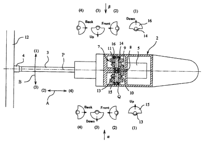
Fig. 1 is a perspective view of a concrete drill.
Fig. 2 is a longitudinal sectional viewof the above concrete
drill.
Fig. 3 is a main portion sectional view of a plane of
the above concrete drill, and a diagram showing a relation
between eccentric weights and forces.
Fig. 4(a) is a delay control block diagram.
Fig. 4(b) is a delay control block diagram.
Fig. 5 is a graph showing an advantage obtained by operation
of a vibrating apparatus.
Description of Reference Numerals and Signs
[0018]
- 9 -
CA 02600048 2007-08-20
1 Concrete drill
2 Drill body
3 Bit drive shaft
15, 16 Eccentric weights
Best Mode for Carrying Out the Invention:
[0019]
Referring to drawings, an example of a drill tool according
to an embodiment of the invention will be described below.
In Fig. 1, numeral 1 designates a concrete drill. The concrete
drill 1 drills concrete by driving rotation of a bit drive
shaft 3 by means of a drive source contained in a drill body
2, and by rotating a diamond bit 4 attached to a front end
of the bit drive shaft 3 projected from a front end of the
drill body 2.
[0020]
In the drill body 2, as shown in Fig. 2, there are provided
a motor 5 for a vibrating apparatus and a motor 6 for a bit
drive shaft which are operated as drive sources by electric
power. The operation of the vibrating apparatus motor 5 is
coupled to a vibrating apparatus 7. Namely, as shown in Fig.
3, a bevel gear 9 (drive bevel gear 9) is fixed to an output
shaft 8 of the vibrating apparatus motor 5, and two bevel gears
10, 11 (first driven bevel gear 10, second driven bevel gear
11) which are opposed to each other mesh with the bevel gear
9 on left and right sides of the bevel gear 9. To rotation
- 10 -
CA 02600048 2007-08-20
shafts 13, 14 of the respective bevel gears 10, 11 opposed
to each other, eccentric weights 15, 16 are integrally fixed
respectively. The eccentric weights 15, 16 are formed
semicircularly, and have a shaft hole in the center respectively.
The eccentric weights 15, 16 rotate integrally with the bevel
gears 10, 11 respectively.
[0021]
According to the above constitution, when the vibrating
apparatus motor 5 is operated, its rotational force is
transmitted through the bevel gears 9, 10, and 11 to the eccentric
weights 15, 16, and thereafter, the two eccentric weights 15,
16 which are opposed to each other rotate in the reverse direction
to each other.
[0022]
Next, as shown in Fig. 2, the operation of the bit drive
shaft motor 6 is coupled to a drive unit. Namely, a gear 18
is formed at an output shaft 17 of the bit drive shaft motor
6, and the gear meshes through a reduction gear 19 located
intermediately with a gear 20 of the bit drive shaft 3. The
bit drive shaft 3 projects from a front end of the drill body
2. To a front end of the bit drive shaft 3, the diamond bit
4 is attached.
[0023]
As shown in Fig. 3, the output shaft 8 of the vibrating
apparatus motor 5 and the bit drive shaft 3 are located on
the same axial line P. Further, the above two eccentric weights
- 11 -
CA 02600048 2007-08-20
15 and 16 are arranged on the opposite sides to each other
centered with respect to the axial line P of the bit drive
shaft 3 and on the same axial line Q orthogonal to the axial
line P, and they are opposed to each other in positions which
are distant equally from an intersection of the axial lines
P and Q. Further, the two eccentric weights 15 and 16 are
arranged, when the drill body 2 is viewed from an a-side and
a(3-side, so that when one of them faces in front or in the
rear, the other also faces on the same side. Namely, when
one 15 of the two eccentric weights faces on one side (front
side) in the axial direction of the bit drive shaft 3, the
other 16 of the two eccentric weights also faces on one side
(front side) in the axial direction of the bit drive shaft
3; and when one 15 of the two eccentric weights faces on the
other side (rear side) in the axial direction of the bit drive
shaft 3, the other 16 of the two eccentric weights also faces
on the other side (rear side) in the axial direction of the
bit drive shaft 3.
[0024]
Further, the drill body 2 includes a power code 21, a
main switch 22, and a control circuit 23. The control circuit
23 is constituted so that power is supplied to the vibrating
apparatus motor 5 later than to the bit drive shaft motor 6.
Such the delay control is carried out by delaying the power
supply to the vibrating apparatus motor 5 by the control circuit
23 as shown in Fig. 4(a), or by perceiving a load of the bit
- 12 -
CA 02600048 2007-08-20
drive shaft motor 6 by the control circuit 23 and thereafter
supplying the power to the vibrating apparatus motor 5 as shown
in Fig. 4(b).
[0025]
Next, an operation mode of the concrete drill will be
described. Firstly, when the main switch 22 is switched on,
the bit drive shaft motor 6 operates, and sequentially the
vibrating apparatus motor 5 operates.
[0026]
When the bit drive shaft motor 6 thus operates, the rotation
of the output shaft 17 is transmitted through the gears 18,
19 and 20 to the bit drive shaft 3, and the diamond bit 4 located
at the front end of the bit drive shaft also rotates. Therefore,
the diamond bit 4 is pressed on the concrete, thereby to drill
the concrete 12.
[0027]
Next, the vibrating apparatus motor 5 operates later than
the bit drive shaft motor 6. Since the rotation of the output
shaft 8 of the motor is transmitted through the bevel gear
9 to the bevel gears 10, 11 opposite to each other, the two
eccentric weights 15, 16 opposite to each other rotate
simultaneously in the reverse direction to each other.
[0028]
Since the eccentric weights 15, 16 rotate in the reverse
direction to each other, when the phase of one rotation is
shifted 90 degrees by 90 degrees, the following forces are
- 13 -
CA 02600048 2007-08-20
applied to the concrete drill as shown in Fig. 3. In (1),
the eccentric weight 15 rotates upward and the eccentric weight
16 rotates downward, so that torsion is applied to the drill
body 2. In (2), the eccentric weight 15 rotates forward (on
the diamond bit 4 side) and the eccentric weight 16 rotates
also forward, so that the vibrating force is applied to the
drill body 2. In (3), the eccentric weight 15 rotates downward
and the eccentric weight 16 rotates upward, so that torsion
is applied to the drill body 2. In (4), the eccentric weight
15 rotates backward and the eccentric weight 16 rotates also
backward, so that the vibrating force is applied to the drill
body 2.
[0029]
Thus, to the concrete drill 1, in the above (2) and (4),
the vibrating force of the same phase along the bit drive shaft
3, is applied as shown by an arrow A in Fig. 3, and in the
(1) and (3) , vibrating moment of the reverse phase on the basis
of torsion in the rotational direction of the bit drive shaft
3 is applied as shown by an arrow B in Fig. 3. Each magnitude
of the vibrating force and the vibrating moment changes
pulsatively in relation to the rotation of the bit drive shaft
3. The above is shown in graphs in Fig. S.
[0030]
When the vibrating force and the vibrating moment act
in the starting time by operating the bit drive shaft 3 and
the vibrating 7 simultaneously, the drill body 2 is vibrated
- 14 -
CA 02600048 2007-08-20
slightly by the vibrating apparatus 7, and the front end of
the diamond bit 4 leaps up from the face of the concrete 5,
so that positioning of the diamond bit 4 becomes difficult.
However, by making power supply to the vibrating apparatus
motor 5 later than power supply to the bit drive shaft motor
6, drilling firstly starts to secure the drilling position
exactly, and thereafter the vibrating apparatus 7 operates,
with the result that positioning becomes easy.
[0031]
As described above, according to the above concrete drill,
the following operational advantages can be obtained. (a)
Since the vibrating force which acts in the axial direction
of the bit drive shaft 3, a magnitude of which pulsates, and
the vibrating moment which acts in the rotational direction
of the bit drive shaft, a magnitude of which pulsates, are
generated on the bit drive shaft, the pressing force of the
drill tool can be obtained from the total of the operator's
pressing force and the vibrating force. Therefore, the
operator's pressing force can be compensated by the vibrating
force. (b) By exerting the vibrating moment, a magnitude of
which pulsates, to the rotational direction of the bit drive
shaft 3, the rotation torque of the bit drive shaft 3 can be
obtained from the total of the output of the drive source and
the vibrating moment. Therefore, a state where the thus obtained
rotational torque is larger than the rotational torque obtained
from only the output of the drive source can be obtained.
- 15 -
CA 02600048 2007-08-20
Accordingly, drilling with small pressing force is possible,
and the drilling speed can be accelerated. (c) By pulsatively
exerting the vibrating force in the axial direction and the
vibrating moment in the rotational direction, the cut concrete
powders are readily exhausted. Therefore, the drill tool is
difficult to be affected by the cut concrete powders, with
the result that stable drilling is possible. (d) When the
diamond bit 4 carries out drilling in a state where the pressing
force is insufficient, the diamond bit 4 runs idle and the
cutting quality lowers, so that it is necessary to recover
the cutting qualitybymaintaining the diamondbit 4 by a grinding
operation. However, in the invention, by pulsatively exerting
the vibrating force to the axial direction of the bit drive
shaft and the vibrating moment in the rotational direction
of the bit drive shaft, drilling can be carried out in a suitable
state. Therefore, idle running of the diamond bit 4 can be
reduced, so that the maintenance of the diamond bit 4 can be
reduced. (e) The two eccentric weights 15, 16 which are
arranged on the same axial line orthogonal to the axial line
of the bit drive shaft 3 and opposite to each other in the
nearly symmetrical positions about the axial line of the bit
drive shaft 3 are driven in the rotational directions reverse
to each other by the eccentric weight drive part composed of
the drive shafts arranged on the same axial line, whereby the
vibrating force and the vibrating moment are generated.
Therefore, the concrete drill of the invention does not have
- 16 -
CA 02600048 2007-08-20
the mechanism that force by which a bit tool such as a diamond
bit can be displaced, such as the striking force by the striking
mechanism of the hammer drill and the vibration force by the
vibration mechanism of the vibration drill, is applied to the
bit tool to subject the concrete to the impact fracture.
Therefore, the silent operation in construction is possible.
(f) By making a start of the eccentric weights 15, 16 later
than a start of the bit drive shaft 3, the vibrating force
and the vibrating moment are generated late for the drive of
the rotation of thebit drive shaft 3. Therefore, after drilling
operation has been started with only the rotation of the diamond
bit and the drilling position has been secured exactly, the
drilling operation with the vibrating force and the vibrating
moment are carried out, so that positioning of the diamond
bit 4 in the drilling position becomes easy and operability
improves.
[0032]
Actually, when the concrete drill mounted with the vibrating
apparatus of the invention was executed, it was confirmed that
the drilling speed was accelerated by about 20%, compared with
the concrete drill mounted with the conventional vibrating
apparatus.
[0033]
The eccentric amounts of the eccentric weights 15, 16
may be determined on the basis of the vibrating force. The
vibrating moment may be adjusted by changing the distance of
- 17 -
CA 02600048 2007-08-20
the eccentric weights 15, 16 from the intersection of the axial
lines P and Q.
[0034]
Though the concrete drill using the substantially solid
diamond bit have been described in the above embodiment, the
invention maybe applied to a concrete drill using a substantially
hollow diamond bit referred to as a core drill.
[0035]
Although the invention has been described in detail and
with reference to a specified embodiment, it will be obvious
to those skilled in the art that various changes andmodification
may be made without departing from the spirit and scope of
the invention.
[0036]
The application is based on Japanese Patent Application
(No. 2005-048790) filed on February 24, 2005, the contents
of which are herein incorporated by reference.
Industrial Applicability:
[0037]
According to the embodiment of the invention, there is
provided a concrete drill which can accelerate more a drilling
speed even with small pressing force.
- 18 -