Note: Descriptions are shown in the official language in which they were submitted.
CA 02600173 2007-09-04
GUIDEWIRE STRUCTURE INCLUDING A MEDICAL GUIDEWIRE
AND METHOD FOR USING
[0001] Field of the Invention
[0002] The present invention is related generally to guidewire structures, and
more particularly to a guidewire structure having a medical guidewire.
[0003] Background of the Invention
[0004] A physician typically accesses and visualizes tissue within a patient's
gastrointestinal (GI) tract with an endoscope (such as a gastroscope or a
colonoscope) having a long, flexible insertion tube. For the upper GI, a
physician may insert a gastroscope into the sedated patient's mouth to examine
and treat tissue in the esophagus, stomach, and proximal duodenum. For the
lower GI, a physician may insert a colonoscope through the sedated patient's
anus to examine the rectum and colon. Some endoscopes have a working
channel in the insertion tube, typically about 2.5-3.5 millimeters in
diameter,
extending from a port in the handpiece to the distal portion of the insertion
tube.
A physician may insert medical devices into the working channel to help
diagnose or treat tissue within the patient.
[0005] Guidewires have been used to aid the introduction of catheters (such as
insertion tubes of endoscopes) and other instruments into many sites in the
human body. Many medical applications and specific designs of guidewires
have been for cardiovascular use. There are, however, specific challenges
relating to the use of guidewires in the GI tract, as opposed to the vascular
system. Thus, the bowel is more tortuous, softer and generally of larger
diameter. Furthermore, in the case of the small intestine and the colon, these
are longer than most arteries or veins.
[0006] Still, scientists and engineers continue to seek improved guidewire
structures having a medical guidewire.
[0007] Summary
CA 02600173 2007-09-04
[0008] A first expression of an embodiment of a guidewire structure of the
invention includes a medical guidewire and an overtube. The medical
guidewire includes a first segment and a lengthwise-adjoining second segment.
The overtube is adapted to slidably cover the first segment and to slidably
expose the first segment. A minimum force required to slide the exposed first
segment over patient tissue is greater than a minimum force required to slide
the
covered first segment over the patient tissue.
[0009] A second expression of an embodiment of a guidewire structure of the
invention includes a medical guidewire and an overtube. The medical
guidewire includes a working portion which is extendable beyond a distal end
of a medical instrument. The working portion includes a first segment and a
lengthwise-adjoining second segment. The overtube surrounds the medical
guidewire and is adapted to slidably cover the first segment and to slidably
expose the first segment. A minimum force required to slide the exposed first
segment over patient tissue is greater than a minimum force required to slide
the
covered first segment over the patient tissue.
[0010] A method of the invention is for using a guidewire structure. The
guidewire structure includes a medical guidewire and an overtube. The medical
guidewire includes a working portion which is extendable beyond a distal end
of an insertion tube of an endoscope, wherein the working portion includes a
first segment and a lengthwise-adjoining second segment. The overtube is
adapted to slidably cover the first segment and to slidably expose the first
segment. A minimum force required to slide the exposed first segment over
patient tissue is greater than a minimum force required to slide the covered
first
segment over the patient tissue, and a minimum force required to slide the
exposed first segment over the patient tissue is greater than a minimum force
required to slide the second segment over the patient tissue. The method
includes inserting the distal end of the insertion tube an initial distance
into a
body lumen of a patient. The method also includes extending at least a portion
of the second segment beyond the distal end of the insertion tube. The method
also includes extending at least a portion of the first segment beyond the
distal
2
CA 02600173 2007-09-04
end of the insertion tube with the overtube covering the extended first
segment.
The method also includes sliding the overtube off the extended first segment
exposing the extended first segment. The method also includes advancing the
insertion tube along the exposed and extended first segment further into the
body lumen of the patient.
[0011] Several benefits and advantages are obtained from one or more of the
expressions of an embodiment and the method of the invention. In one
example, having a "non-sticky" overtube and having a loop-track or non-loop-
track medical guidewire including a "sticky" first segment which can be
slidably covered and slidably exposed by the overtube is expected to allow
easier extension of the covered first segment in a body lumen of a patient
followed by improved anchoring of the uncovered first segment against patient
tissue resulting in improved advancement of an endoscope insertion tube along
the anchored uncovered first segment.
[0012] Brief Description of the Figures
[0013] FIGURE 1 is a schematic side-elevational cutaway view of a first
embodiment of a medical instrument having a catheter and employing an
embodiment of a guidewire structure of the invention, wherein the guidewire
structure has a medical guidewire and an overtube, wherein the medical
guidewire is employed as a loop-track guidewire, wherein a shortened view of
the entire working portion of the medical guidewire is shown extending beyond
the distal end of the catheter, and wherein the overtube has been pulled to
slidingly expose a first segment of the medical guidewire;
[0014] FIGURE 2 is a view as in Figure 1 but previous in time to Figure 1,
wherein the overtube has been pushed to slidingly cover the first segment of
the
medical guidewire before the covered first segment was extended beyond the
distal end of the catheter;
[0015] FIGURE 3 is a straightened side-elevational view of the working
portion of the medical guidewire of Figure 1;
3
CA 02600173 2007-09-04
[0016] FIGURE 4 is a cross-sectional view of the first segment of the working
portion of the medical guidewire of Figure 3 taken along lines 4-4 of Figure
3;
[0017] FIGURE 5 is a cross-sectional view of the second segment of the
working portion of the medical guidewire of Figure 3 taken along lines 5-5 of
Figure 3;
[0018] FIGURE 6 is a cross-sectional view of the guidewire structure of
Figure 1 taken along lines 6-6 of Figure 1 showing the overtube surrounding a
leg of the medical guidewire;
[0019] FIGURE 7 is a schematic side-elevational cutaway view of a second
embodiment of a medical instrument having a catheter and employing an
alternate embodiment of a guidewire structure of the invention, wherein the
guidewire structure has a medical guidewire and an overtube, wherein the
medical guidewire has the working portion of Figure 3 and is employed as a
non-loop-track guidewire, wherein a shortened view of the entire working
portion of the medical guidewire is shown extending beyond the distal end of
the catheter, and wherein the overtube has been pulled to slidingly expose a
first
segment of the medical guidewire; and
[0020] FIGURE 8 is a view as in Figure 7 but previous in time to Figure 7,
wherein the overtube has been pushed to slidingly cover the first segment of
the
medical guidewire before the covered first segment was extended beyond the
distal end of the catheter.
[0021] Detailed Description
[0022] Before explaining the several embodiments of the present invention in
detail, it should be noted that each embodiment is not limited in its
application
or use to the details of construction and arrangement of parts and steps
illustrated in the accompanying drawings and description. The illustrative
embodiments of the invention may be implemented or incorporated in other
embodiments, variations and modifications, and may be practiced or carried out
in various ways. Furthermore, unless otherwise indicated, the terms and
4
CA 02600173 2007-09-04
expressions employed herein have been chosen for the purpose of describing the
illustrative embodiments of the present invention for the convenience of the
reader and are not for the purpose of limiting the invention.
[0023] It is further understood that any one or more of the following-
described embodiments, examples, etc. can be combined with any one or more
of the other following-described embodiments, examples, etc.
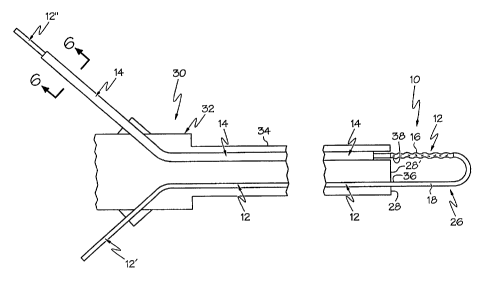
[0024] An embodiment of a guidewire structure 10 of the invention is shown
in Figures 1-6. A first expression of the guidewire structure 10 of the
embodiment of Figures 1-6 includes a medical guidewire 12 and an overtube
14. The medical guidewire 12 includes a first segment 16 and a lengthwise-
adjoining second segment 18. The overtube 14 is adapted to slidably cover the
first segment 16 (as shown in Figure 2) and to slidably expose the first
segment
(as shown in Figure 1). A minimum force required to slide the exposed first
segment 16 over patient tissue is greater than a minimum force required to
slide
the covered first segment 16 over the patient tissue.
[0025] It is noted that the exposed first segment 16 when slidingly pushed
over patient tissue sticks more to the patient tissue than does the covered
first
segment 16 when likewise slidingly pushed over the patient tissue. In one
example, a minimum force required to slide the exposed first segment 16 over
the patient tissue is greater than a minimum force required to slide the
(exposed)
second segment 18 over the patient tissue. It is also noted that the exposed
first
segment when slidingly pushed over the patient tissue sticks more to the
patient
tissue than does the (exposed) second segment 18 when likewise slidingly
pushed over the patient tissue.
[0026] In one enablement of the first expression of the embodiment of Figures
1-6, the overtube 14 is flexible. In one variation, the medical guidewire 12
is
resiliently flexible. In one modification, each of the first and second
segments
16 and 18 is resiliently flexible.
CA 02600173 2007-09-04
[0027] In one construction of the first expression of the embodiment of
Figures 1-6, the first segment 16 includes a first length of a core wire 20
and a
mesh 22 surrounding, and attached to, the first length of the core wire 20. In
one method, the mesh 22 is attached to the first length of the core wire 20 by
an
adhesive. In another method, not shown, a thin wall sleeve surrounds the mesh
and is crimped against the core wire to trap the mesh between the sleeve and
the
core wire. In a further method, a heat shrinkable material surrounds the mesh
and is heat shrunk against the core wire to trap the mesh between the sleeve
and
the core wire. Other methods are left to the artisan. In one example, the core
wire 20 consists essentially of a monolithic length of a super-elastic alloy
such
as nitinol available from Nitinol Devices & Components (Fremont, CA). In the
same or a different example, the mesh 22 consists essentially of polypropylene
such as Gynemesh surgical mesh available from Johnson & Johnson
Corporation (New Brunswick, NJ). In the same or a different example, the
overtube 14 is a lubricious overtube such as one consisting essentially of
Polytetrafluoroethylene (PTFE), such as Teflori PTFE available from Zeus, Inc
(Orangeburg, SC). It is noted that the mesh 22 sticks to patient tissue more
than
does the overtube 14. In non-mesh constructions, not shown, the first segment
has a shape (such as a corrugated shape), a texture, a surface roughness (such
as
that of a pitted or sandblasted surface), or a series of projections (such as
bristles) that tend to grip onto tissue.
[0028] In the same or a different construction, the second segment 18 consists
essentially of a second length of the core wire 20 and a lubricious sleeve 24
surrounding, and attached to, the second length of the core wire 20. In one
variation, the first and second lengths are portions of a monolithic length of
the
core wire 20. Examples of materials for the lubricious sleeve 24 include,
without limitation, Polytetrafluoroethylene (PTFE), such as Striped Teflon
PTFE available from Zeus, Inc (Orangeburg, SC). In one method, the
lubricious sleeve 24 is applied over the second length of the core wire 20
through a heat-shrink process well known in the art. It is noted that the mesh
22
sticks to patient tissue more than does the lubricious sleeve 24.
6
CA 02600173 2007-09-04
[0029] A second expression of the guidewire structure 10 of the embodiment
of Figures 1-6 includes a medical guidewire 12 and an overtube 14. The
medical guidewire 12 includes a working portion 26 which is extendable
beyond a distal end 28 of a medical instrument 30. The working portion 26
includes a first segment 16 and a lengthwise-adjoining second segment 18. The
overtube 14 surrounds the medical guidewire 12 and is adapted to slidably
cover
the first segment 16 (as shown in Figure 2) and to slidably expose the first
segment (as shown in Figure 1). A minimum force required to slide the
exposed first segment 16 over patient tissue is greater than a minimum force
required to slide the covered first segment 16 over the patient tissue.
[0030] It is noted that the working portion 26 is a maximum portion of the
medical guidewire 12 which can be extended beyond the distal end 28 of the
medical instrument 30. Some applications of the guidewire structure 10 may
require the entire working portion 26 to be extended beyond the distal end 28
while other applications may require less than the entire working portion 26
to
be extended beyond the distal end 28. It is also noted that in some
applications,
the medical guidewire 12 is manually pushed (as intended by Figures 1 and 2)
to extend at least some of the working portion 26 beyond the distal end 28,
that
in other applications a hand crank (not shown) is used to extend at least some
of
the working portion 26, and that in still other applications a motor (not
shown)
is used to extend at least some of the working portion 26. It is further noted
that
the examples, enablements, constructions, etc. of the first expression of the
embodiment of Figures 1-6 are equally applicable to the second expression of
the embodiment of Figures 1-6.
[0031] In one application of the second expression of the embodiment of
Figures 1-6, the medical instrument 30 is an endoscope 32 having a flexible
insertion tube 34. In this application, the distal end 28 of the medical
instrument is a distal end 28' of the insertion tube 34. In one variation, the
working portion 26 is extendable beyond the distal end 28' of the insertion
tube
34 from within the insertion tube 34.
7
CA 02600173 2007-09-04
[0032] In a first deployment of the second expression of the embodiment of
Figures 1-6, the working portion 26 is extendable as a loop track (as shown in
Figures 1 and 2) beyond the distal end 28' of the insertion tube 34. Here, the
length of the working portion 26 is a loop-track length of the working portion
26. In one construction, the loop-track length of the working portion 26 is at
least six feet, and the working portion 26 has a substantially circular cross-
section having a maximum diameter which is always less than 0.050-inch and a
minimum diameter which is always at least 0.010-inch.
[0033] In a first arrangement of the second expression of the embodiment of
Figures 1-6, the working portion 26 extends as a loop track, the medical
guidewire 12 includes a first leg 12' monolithically attached to and extending
from a first end 36 of the working portion 26 (which is a proximal end of the
second segment 18) proximally through a first passageway of the insertion tube
34 and outside the endoscope 32, and the medical guidewire 12 includes a
second leg 12" monolithically attached to and extending from a second end 38
of the working portion 14 (which is a proximal end of the first segment 16)
proximally through a second passageway of the insertion tube 34 and outside
the endoscope 32. In a second arrangement, not shown, the first and second
legs 12' and 12" extend through a single passageway such as a working channel
of the insertion tube. In a third arrangement, not shown, the loop track
extends
beyond the distal end of the insertion tube from outside the exterior surface
of
the insertion tube with the first and/or second legs engaged by guide ways on
the exterior surface of the insertion tube. Other arrangements are left to the
artisan.
[0034] In a second deployment (shown in the alternate embodiment of Figures
7-8), a guidewire structure 110 includes a medical guidewire 112 having the
working portion 26 shown in Figure 3, but the guidewire structure 110 is
employed as a non-loop-track in a different endoscope 132 having an insertion
tube 134. Here, the second segment 18 has a free end 36 which extends beyond
the distal end 128 of the insertion tube 134 when the working portion 26 is
8
CA 02600173 2007-09-04
extended beyond the distal end 128 of the insertion tube 134 The first segment
16 is exposed in Figure 7 and is covered by the overtube 114 in Figure 8.
[0035] In a different embodiment of the guidewire structure, not shown, the
working portion of the medical guidewire consists essentially of the first
segment. In one deployment, the working portion is a loop-track working
portion. In a different deployment, the working portion is a non-loop-track
working portion.
[0036] A method of the invention is for using a guidewire structure 10. The
guidewire structure 10 includes a working portion 26 which is extendable
beyond a distal end 28' of an insertion tube 34 of an endoscope 32, wherein
the
working portion 26 includes a medical guidewire 12 and an overtube 14. The
medical guidewire 12 includes a first segment 16 and a lengthwise-adjoining
second segment 18. The overtube 14 is adapted to slidably cover the first
segment 16 and to slidably expose the first segment 16. A minimum force
required to slide the exposed first segment 16 over patient tissue is greater
than
a minimum force required to slide the covered first segment 16 over the
patient
tissue, and a minimum force required to slide the exposed first segment 16
over
the patient tissue is greater than a minimum force required to slide the
second
segment 18 over the patient tissue. The method includes steps a) through e).
Step a) includes inserting the distal end 28' of the insertion tube 34 an
initial
distance into a body lumen of a patient. Step b) includes extending at least a
portion of the second segment 18 beyond the distal end 28' of the insertion
tube
34. Step c) includes extending at least a portion of the first segment 16
beyond
the distal end 28' of the insertion tube 34 with the overtube 14 covering the
extended first segment 16. Step d) includes sliding the overtube 14 off the
extended first segment 16 exposing the extended first segment 16. Step e)
includes advancing the insertion tube 34 along the exposed and extended first
segment 16 further into the body lumen of the patient.
[0037] In one implementation of the method, step c) includes manually
pulling the overtube 14 slidingly off the extended first segment 16. In a
9
CA 02600173 2007-09-04
different implementation, step c) includes using a motor to pull the overtube
slidingly off the extended first segment.
[0038] Several benefits and advantages are obtained from one or more of the
embodiments and the method of the invention. In one example, having a "non-
sticky" overtube and having a loop-track or non-loop-track medical guidewire
including a "sticky" first segment which can be slidably covered and slidably
exposed by the overtube is expected to allow easier extension of the covered
first segment in a body lumen of a patient followed by improved anchoring of
the uncovered first segment against patient tissue resulting in improved
advancement of an endoscope insertion tube along the anchored uncovered first
segment.
[0039] While the present invention has been illustrated by descriptions of a
method, several expressions of embodiments, and examples, etc. thereof, it is
not the intention of the applicants to restrict or limit the spirit and scope
of the
appended claims to such detail. Numerous other variations, changes, and
substitutions will occur to those skilled in the art without departing from
the
scope of the invention. It will be understood that the foregoing description
is
provided by way of example, and that other modifications may occur to those
skilled in the art without departing from the scope and spirit of the appended
Claims.
WHAT IS CLAIMED IS: