Note: Descriptions are shown in the official language in which they were submitted.
CA 02600357 2007-09-06
WO 2006/102316 PCT/US2006/010217
1
DIAGNOSTIC CIRCUIT
FIELD OF THE INVENTION
[0001] This invention generally relates to diagnostic circuits used to monitor
the
operation of an electrical component in a floating ground environment. In
particular, the
invention relates to diagnostic circuits employed in appliances.
BACKGROUND OF THE INVENTION
[0002] Current sensing diagnostic circuits are often used in appliances (e.g.,
refrigerators) to monitor the operation of electrical components such as, for
example, relay
circuits. Such a current sensing diagnostic circuit is illustrated in
simplified schematic form
in FIG. 1. If a current begins to flow through the diagnostic circuit when the
relay is
commanded to close, a sensor detects that current and reports that the
electrical component
being monitored is operating as intended. If, however, current does not flow
through the
diagnostic circuit when the relay is commanded to close, the sensor notes the
absence of
that current and reports to the control and/or microprocessor that the
electrical component is
not functioning properly. When the electrical component is not working,
malfunctioning,
and the like, a teclulician is often sumunoned to repair and/or replace the
electrical
component in the appliance. Unfortunately, indication of a failure of the
electrical
component to function properly can occur when a variety of different faults
(e.g., an open
load, a disconnected wire, and the like) are experienced and/or the electrical
component
itself is damaged. Therefore, the technician will have to check a number of
different
potential problems to determine which electrical component has actually
failed, which
electrical component needs to be replaced, which leads or connections to
check, and the
like.
[0003] Another method is to look for line voltage at the output of the relay.
Referring to
FIGS. 2-5, one such conventional voltage sensing diagnostic circuit 10, as
known in the art,
is illustrated. The known diagnostic circuit 10 includes a variety of
resistors 12, 14, 16, 18,
and a capacitor 20 coupled together as shown to sense the applied voltage from
the relay
circuit 22 to the load 24. The diagnostic circuit 10 is typically coupled to a
sensing circuit
30 at node 32, whicli provides the diagnostic information to a controller or
microprocessor
42.
CA 02600357 2007-09-06
WO 2006/102316 PCT/US2006/010217
2
[0004] The relay circuit 22 includes an electromagnetic coil 34 and a switch
36. The
electromagnetic coil 34 is coupled to a direct current power source 38 and a
driver circuit
40. The driver circuit 40 is typically commanded by the microprocessor 42 to
switch the
alternating-current (AC) power source 44 to the load 24.
[0005] Referring specifically to FIG. 3, when the electromagnetic coi134 is de-
energized and the switch 36 is open, the diagnostic circuit 10 does not sense
any voltage
applied to the load 24. This is the normal sense for a relay open condition
using this type of
current sense circuit 10. Unfortunately, since this conventional circuit 10
detects voltage
applied to the load 24, and since the opening of the relay switch 36 ensures
that no voltage
is applied to the load 24, the circuit 10 does not detect anything different
at this point if
there is a fault (open circuit) in the wiring to the load as illustrated in
FIG. 3 or if the load
itself is disconnected. The same can be said for the current sense circuits.
[0006] When the relay 22 is closed under normal operation as shown in FIG. 4,
the
sensing circuit 30 detects the current flow to the load 24. The sensing
circuit 30 then
coinmunicates that the relay circuit 22 is operating noimally as conunanded.
However,
because the circuit 10 is configured to monitor the current flow to the load
24 to determine
if the relay 22 is operating properly, a broken wire to the load 24, as
illustrated in FIG. 5 (or
a disconnection of the load 24 itself) will be flagged as a failure of the
relay 22.
Unfortunately, this may well lead the tecluiician to replace the relay or the
relay board,
when in fact the relay 22 and its driver 40 are operating properly. Further
troubleshooting
would then be required to isolate the problem detected by circuit 10.
[0007] For the convenience of the reader, a summary of the operation of the
l:nown
diagnostic circuit 10 is provided in FIG. 6. As illustrated in the first two
rows of the truth
table, anytime the switch 36 in relay circuit 22 is open, whether or not the
load 24 is
coiuiected or unconnected, the sensing circuit 30 sees no current. In
contrast, as sliown in
the third row of the truth table, when the switch 36 in relay circuit 22 is
closed and the load
24 is connected, the sensing circuit 30 sees the current flow to that load.
This is interpreted
as normal relay operation. However, even if the relay 22 operates normally and
closes its
switch 36, if the load is disconnected, the circuit 10 does not see current
flowing to the load.
This is reported as a failed relay 22, even though it operated to close its
switch 36 when
commanded. As a result, faults in the relay circuit 22, the load 24, or
elsewhere are difficult
to locate, pinpoint, and troubleshoot.
[0008] Therefore, a diagnostic circuit that can indicate whether a load is
present or
missing, as well as determine if a relay circuit is functioning properly,
would be desirable.
The invention provides such a diagnostic circuit. These and other advantages
of the
CA 02600357 2007-09-06
WO 2006/102316 PCT/US2006/010217
3
invention, as well as additional inventive features, will be apparent fi=om
the description of
the invention provided herein.
BRIEF SUMMARY OF THE INVENTION
[0009] In one aspect, the invention provides a floating diagnostic circuit
coupled to a
load node between a relay circuit and a load. The floating diagnostic circuit
comprises a
first resistor, a capacitor, a second resistor, and a third resistor. The
first resistor is disposed
between a node and a sensing node. The capacitor is disposed between the
sensing node
and a ground node. The second resistor is disposed between the node and the
ground node.
The second resistor is coupled to the first resistor at the node and is
coupled to the capacitor
at the ground node. The third resistor is disposed between the node and the
load node. The
third resistor is coupled to the first resistor and the second resistor at the
node.
[0010] In another aspect, the invention provides a diagnostic circuit system
for
determining the proper operation of a relay circuit and the status of a
connection of a load
thereto. The diagnostic circuit system comprises a diagnostic circuit and a
sensing circuit.
[0011] The diagnostic circuit has a first resistor, a capacitor, a second
resistor, and a
third resistor. The first resistor is disposed between a node and a sensing
node. The
capacitor is disposed between the sensing node and a ground node. The second
resistor is
disposed between the node and the ground node. The third resistor is disposed
between the
node and a load node. The third resistor is coupled to the first resistor and
the second
resistor at the node. The sensing circuit is coupled to the diagnostic circuit
at the sensing
node.
[0012] The diagnostic circuit generates a high voltage at the sensing node
when the
relay circuit is closed, a low voltage when the relay circuit is open and the
load is
discoimected from the relay circuit, and an oscillating voltage when the relay
circuit is open
and the load is connected to the relay circuit.
[0013] In a further aspect, the invention provides a diagnostic circuit
system. The
diagnostic circuit systein comprises a diagnostic circuit, a relay circuit,
and a sensing
circuit.
[0014] The diagnostic circuit has a first resistor, a capacitor, a second
resistor, and a
third resistor. The first resistor is disposed between a node and a sensing
node. The
capacitor is disposed between the sensing node and a ground node. The
capacitor is
CA 02600357 2007-09-06
WO 2006/102316 PCT/US2006/010217
4
coupled to the first resistor at the sensing node such that the first resistor
and capacitor are
in series. The second resistor is disposed between the node and the ground
node. The
second resistor is coupled to the first resistor at the node and coupled to
the capacitor at the
ground node such that the second resistor is in parallel with the first
resistor and the
capacitor. The third resistor is disposed between the node and a load node.
The third
resistor is coupled to the first resistor and the second resistor at the node
such that the third
resistor is in series with the second resistor and the first resistor and the
capacitor.
[0015] The relay circuit is coupled to the diagnostic circuit at the load node
and the
sensing circuit is coupled to the diagnostic circuit at the sensing node. The
diagnostic
circuit generates, and the sensing circuit detects, one of an oscillating
signal, a logic high,
and a logic low such that a presence of a load and proper operation of the
relay circuit are
confirmed.
[0016] Other aspects, objectives and advantages of the invention will become
more
apparent from the following detailed description when taken in conjunction
with the
accompanying drawings.
BRIEF DESCRIPTION OF THE DRAWINGS
[0017] The accompanying drawings incorporated in and forming a part of the
specification illustrate several aspects of the present invention and,
together with the
description, serve to explain the principles of the invention. In the
drawings:
[0018] FIG.1 is a prior art current sensing diagnostic circuit in simplified
schematic
form.
[0019] FIG. 2 is a schematic of a prior art diagnostic circuit system having
an "open"
relay circuit and a connected load;
[0020] FIG. 3 is a schematic of the prior art diagnostic circuit system of
FIG. 2 having
an "open" relay circuit and a discoiuiected load;
[0021] FIG. 4 is a schematic of the prior art diagnostic circuit system of
FIG. 2 having a
"closed" relay circuit and a connected load;
[0022] FIG. 5 is a schematic of the prior art diagnostic circuit system of
FIG. 2 having a
"closed" relay circuit and a disconnected load;
CA 02600357 2007-09-06
WO 2006/102316 PCT/US2006/010217
[0023] FIG. 6 is a ttuth table summarizing the operational information of the
prior art
diagnostic circuit systems of FIGS. 2-5;
[0024] FIG. 7 is a schematic of an exemplary embodiment of a diagnostic
circuit system
constructed in accordance with the teachings of the present invention and
having an "open"
relay circuit and a connected load;
[0025] FIG. 8 is a schematic of the diagnostic circuit system of FIG. 7 having
an "open"
relay circuit and a disconnected load;
[0026] FIG. 9 is a schematic of the diagnostic circuit system of FIG. 7 having
an "open"
relay circuit and a disconnected load; and
[0027] FIG. 10 is a truth table summarizing the operational information of the
diagnostic circuit systems of FIGS. 7-9.
[0028] While the invention will be described in connection with certain
preferred
embodiments, there is no intent to limit it to those embodiments. On the
contrary, the intent
is to cover all alternatives, modifications and equivalents as included within
the spirit and
scope of the invention as defined by the appended claims.
DETAILED DESCRIPTION OF THE INVENTION
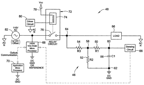
[0029] Referring to FIG. 7, an exemplary embodiment of a diagnostic circuit 46
within
a diagnostic circuit system 48 is illustrated. Diagnostic circuit 46 comprises
a first resistor
50, a second resistor 52, a third resistor 54, and a capacitor 56. The first
resistor 50 is
disposed between a node 58 and a sensing node 60. The capacitor 56 is disposed
between
the sensing node 60 and a ground node 62. The second resistor 52 is disposed
between the
node 58 and the ground node 62. The third resistor 54 is disposed between the
node 58 and
a load node 64.
[0030] In an exemplary embodiment, the first resistor 50 is a one mega ohm (1
M92)
resistor, the second resistor 52 is a 470 kilo olun (470 kS2) resistor, the
third resistor 54 is a
100 kilo olnn (100 kS2) resistor, and the capacitor 56 is a 0.001 micro-farad
(0.001 F)
capacitor rated at 100 volts. These particular component values are selected
to produce
certain voltages corresponding to a "logic low" and a "logic higli" at sensing
node 60.
Should different voltage levels be desired for the logic low and logic high,
the component
values can be modified.
CA 02600357 2007-09-06
WO 2006/102316 PCT/US2006/010217
6
[0031] The diagnostic circuit 46 is coupled to a sensing circuit 66 at the
sensing node
60. The sensing circuit 66 can include, or be coupled to, a high-voltage
microprocessor 68
(a.k.a., a control). As shown, the sensing circuit 66 can communicate directly
with, and can
be coupled to, the high-voltage microprocessor 68 if the two components are
separated. In
an exemplary embodiment, the high-voltage microprocessor 6S is optically bi-
directionally
coupled to an application microprocessor 70. Since the high-voltage
microprocessor 68 and
the application microprocessor 70 are coupled via an optical connection, the
two
microprocessors are maintained in isolation from one another.
[0032] The diagnostic circuit 46 is connected to monitor the operation of a
relay circuit
72 at the load node 64. The relay circuit 72 includes an electromagnetic coil
74 and a
switch 76. The electromagnetic coil 74 is coupled to a direct current power
source 78 and a
drive circuit 80.
[0033] The switch 76 of the relay circuit 72 is coiinected to an alternating-
current (AC)
voltage source 82. In preferred embodiments, the alternating-current voltage
source 82 is a
one hundred and ten volt (110 V) source with a five volt (5 V) direct current
voltage offset.
In an exemplary embodiment, the microcontroller or microprocessor 68 is hot
(i.e., not
isolated by a transformer). The high-voltage microprocessor 68 is shown
coupled to the
alternating-current voltage source 82 and the relay circuit 72. Even so, the
high-voltage
microprocessor 68 can be coupled elsewhere relative to the diagnostic circuit
46 and/or the
diagnostic circuit system 48.
[0034] As shown in FIG. 7, a load 86 is preferably connected to the relay
circuit 72 at
the load node 64. Due to load faults, broken wires, open loads, and the like,
the load 86 is,
at times, undesirably disconnected from the relay circuit 72 and the
diagnostic circuit
system 48 as illustrated in FIG. 8. Unlike the prior diagnostic circuits
discussed above, the
diagnostic circuit 46 is able to detect the presence and absence of the load
86 as well as
monitor the proper operation of the relay circuit 76.
[0035] In operation, as shown in FIG. 7, when the switch 76 in the relay
circuit 72 is
open (i.e., the electromagnetic coil 74 is de-energized), and the load 86 is
connected or
present, the diagnostic circuit 46 generates an oscillating voltage of about
one hundred volts
(100 V) at sixty Hertz (60 Hz) at the sensing node 58. The resistor Rl 50
current limits the
100 V signal to the sensing circuit 66. In an alternate embodiment, a clamping
diode is used
to protect the sensing circuit 66. This oscillating voltage is sensed or
detected by the
sensing circuit 66. As a result of seeing an oscillating voltage at node 60,
the sensing circuit
66 reports to the high-voltage microprocessor 68 that the load is present or
connected.
CA 02600357 2007-09-06
WO 2006/102316 PCT/US2006/010217
7
[0036] Turning to FIG. 8, when switch 76 in relay circuit 72 is again open,
but the load
86 is disconnected, the diagnostic circuit 46 generates a logic low (e.g., 0
volts) at the
sensing node 60. This logic low is sensed or detected by the sensing circuit
66. As a result
of seeing the logic low at node 60, the sensing circuit 66 reports to the high-
voltage
microprocessor 68 that the load is missing or disconnected. Notably, the
diagnostic circuit
46 is able to determine that the load 86 is not present when the switch 76 is
open. Thus, the
diagnostic circuit 46 alerts the sensing circuit 66 if the load is connected
or disconnected
before the relay circuit 72 is closed.
[0037] Referring to FIG. 9, after the diagnostic circuit 46 and the sensing
circuit 66
have operated to determine if the load 86 is connected or disconnected, the
switch 76 in the
relay circuit 72 can be closed. With the switch 76 closed, the diagnostic
circuit 46 generates
a logic high (e.g., 5 volts) at the sensing node 60. This logic high is sensed
or detected by
the sensing circuit 66. As a result of seeing the logic higli at node 60, the
sensing circuit 66
reports to the high-voltage microprocessor 68 that the relay circuit 72 is
functioning
properly. Node 60 stays at the logic higli until the switch 76 in the relay
circuit 72 is once
again opened, regardless of the presence of the load 86.
[0038] In summary, as shown in the truth table of FIG. 10, the diagnostic
circuit 46
generates an oscillating voltage at sensing node 60 when the relay circuit 72
is open and the
load 86 is connected, generates a logic low at sensing node 60 when the relay
circuit 72 is
open and the load 86 is disconnected, and generates a logic high when the
relay circuit 72 is
closed. As the truth table illustrates, the diagnostic circuit 46 can
determine whether the
load 86 is present or missing before the relay circuit 72 is actuated. This
allows the
detection and isolation of a failed load/wiring condition that otherwise might
be identified
as a failed relay. Moreover, the diagnostic circuit 46 can confirm that the
relay circuit 72 is
operating properly regardless of the presence of the load.
[0039] The diagnostic circuit 46 of the present invention provides many
advantages.
First, the diagnostic circuit 46 of the present invention has fewer parts than
the known
diagnostic circuit 10 discussed above. Moreover, the diagnostic circuit 46
senses a voltage
or a change in voltage as opposed to sensing a current level or lack of
current like the
known diagnostic circuit 10. Further, the diagnostic circuit 46 and diagnostic
circuit system
48 permit board versus load fault detection. As such, faults can be more
easily located and
remedied by, for example, an appliance teclmician.
[0040] All references, including publications, patent applications, and
patents, cited
herein are hereby incorporated by reference to the same extent as if each
reference were
CA 02600357 2007-09-06
WO 2006/102316 PCT/US2006/010217
8
individually and specifically indicated to be incorporated by reference and
were set forth in
its entirety herein.
[0041] The use of the terms "a" and "an" and "the" and similar referents in
the context
of describing the invention (especially in the context of the following
claims) is to be
construed to cover both the singular and the plural, unless otherwise
indicated herein or
clearly contradicted by context. The terms "comprising,"" "having,"
"including," and
"containing" are to be construed as open-ended terms (i.e., meaning
"including, but not
limited to,") unless otherwise noted. Recitation of ranges of values herein
are merely
intended to serve as a shorthand method of referring individually to each
separate value
falling within the range, unless othenvise indicated herein, and each separate
value is
incorporated into the specification as if it were individually recited herein.
All methods
described herein can be performed in any suitable order unless otherwise
indicated herein or
otherwise clearly contradicted by context. The use of any and all examples, or
exemplary
language (e.g., "such as") provided herein, is intended merely to better
illuminate the
invention and does not pose a limitation on the scope of the invention unless
otherwise
claimed. No language in the specification should be construed as indicating
any non-
claimed element as essential to the practice of the invention.
[0042] Preferred embodiments of this invention are described herein, including
the best
mode known to the inventors for carrying out the invention. Variations of
those preferred
embodiments may become apparent to those of ordinary skill in the art upon
reading the
foregoing description. The inventors expect skilled artisans to employ such
variations as
appropriate, and the inventors intend for the invention to be practiced
otherwise than as
specifically described herein. Accordingly, this invention includes all
modifications and
equivalents of the subject matter recited in the claims appended hereto as
permitted by
applicable law. Moreover, any combination of the above-described elements in
all possible
variations thereof is encompassed by the invention unless otherwise indicated
herein or
otherwise clearly contradicted by context.