Note: Descriptions are shown in the official language in which they were submitted.
CA 02600549 2007-09-10
WO 2006/105881
PCT/EP2006/002764
Module front for a switchgear assembly module,
switchgear assembly module and electrical switchgear
assembly
Description
The invention relates to a module front for a
switchgear assembly module, in particular a
withdrawable module, having the features of claim 1 and
to a switchgear assembly module having a module front
according to the invention and an electrical switchgear
assembly, in particular a medium-voltage or low-voltage
switchgear assembly, having at least one such
switchgear assembly module having a module front
according to the invention.
Continuously increasing and often changing demands in
the processing industry and in electrical engineering
bring about the need for the use of medium-voltage and
low-voltage switchgear assemblies which can be
converted and maintained as simply as possible. Current
assemblies in this regard generally have a plurality of
switchgear cabinets which are designed using
withdrawable part technology and are comparatively easy
to fit with components and to configure. Withdrawable
part technology in this context means that all the
electrical operating means and electrical devices, such
as control and/or measuring devices installed as
components, for example, are preferably arranged on
modularized withdrawable parts.
Advantageous here is the simplified accessibility of
the respective withdrawable module by virtue of the
fact that, if required, for example in the event of a
fault or of a failure, but also in the event of the
respective switchgear assembly being reconfigured, this
withdrawable module can be removed easily from the
CA 02600549 2012-09-24
- 2 -
respective switchgear cabinet and replaced by a
suitable module.
Disadvantageously, however, the control and/or
measuring devices installed are in general
conventional, generally available electrical and
electronic components which have not been adapted for
use in withdrawable part technology and which often
require a comparatively large amount of space and cause
increased configurational complexity. In the context of
repair and servicing measures, this then usually also
results in longer maintenance times and downtimes.
Furthermore, the increased amount of space required for
individual components often necessitates physical
overdimensioning of the actual module since, owing to
the specific arrangement and geometry of the individual
components (a module can only be as small as its
largest component), a large proportion of the converted
space is usually unusable.
The object of the invention is to specify, for a given
functionality, a switchgear assembly module having a
control device with simplified handling and improved
utilization of space.
This object is achieved by a switchgear assembly having
the features of the claimed invention, a switchgear
assembly module and a module front having the features
of the claimed invention. Advantageous configurations
of the invention are specified in the dependent claims
and in the description of the figures.
The electrical switchgear assembly according to the
invention in this case has at least one switchgear
assembly module, in particular a withdrawable module,
having a module front having an integrated control
CA 02600549 2007-09-10
WO 2006/105881
PCT/EP2006/002764
- 3 -
device, the module front also being an integral part of
the respective switchgear assembly module.
With the aid of the module front according to the
invention, which is matched to the respective size
requirements of the module technology and has an
integrated control device, it is now possible to make
best possible use of the space available in the
switchgear assembly module in question. Furthermore,
handling of the respective switchgear assembly module
and therefore of the electrical switchgear assembly is
also improved and simplified by virtue of the fact
that, if required, in the event of a fault and/or in
the event of maintenance or servicing work on the
.control device, only the module front according to the
invention needs to be replaced, without the remaining
components and internals of the respective switchgear
assembly module being affected. It is therefore
possible to insert the switchgear assembly module in
the electrical switchgear assembly correctly again as
quickly as possible merely by changing the module
front.
In this case, the control device integrated in the
module front in an advantageous configuration of the
invention comprises a control board, via which control
commands and instructions from an external drive system
are processed and/or are passed on to corresponding
devices and/or internals in the module or said devices
and/or internals are controlled.
Furthermore, it is advantageously possible to provide
that status details or status information relating to
the at least one switchgear assembly module are made
available for callup via a preconfigurable interface.
The preconfigurable interface may in this case be, in
particular, an interface which can be read by a
CA 02600549 2007-09-10
WO 2006/105881
PCT/EP2006/002764
- 4 -
correspondingly set-up data processing device, for
example an RS-232, RS485/RS422 and/or a USB interface.
It is also advantageously possible to provide
conventional power links or bus links for reading the
relevant status information via a corresponding bus
system or control system and/or via a local or global
network, in particular the Internet, for example for
the purpose of a remote diagnosis. As an alternative to
this, interfaces for wireless information transmission
to a corresponding control system and/or a data
processing device set up for this purpose, for example
by means of wireless LAN (WLAN) or Bluetooth, can also
be provided.
In a further embodiment of the invention, a display
device is also integrated in the module front, which
display device visually displays status information
relating to the withdrawable module. In this case, the
display device preferably also comprises an LED board,
which can be populated with a plurality of LEDs and/or
a plurality of colored and/or at least one
monochromatic or multicolored LED in order to display
relevant status information in color-coded fashion.
Furthermore, an adhesive label with an integrated label
carrier can additionally be provided, it being possible
to insert an insert label which can be written on
freely into the'label carrier.
In addition to the visual display of the status
information, an alternative configuration of the
, display device also provides for an acoustic display of
predeterminable status information, for example in the
form of a warning tone or signal generated by an
acoustic signal transmitter when a predetermined module
state is reached, in particular when there is a
functional failure or a functional fault.
CA 02600549 2013-10-10
,
- 5 -
According to an aspect of the present invention there is
provided a module front for a switchgear assembly module,
comprising a front element in the form of a trough and
having a trough base and four inner side walls and four
outer side walls, wherein inner and outer side walls are
arranged spaced apart from one another and enclose an
intermediate space for accommodating the rest of the module
housing, and having a control device, wherein the control
device is arranged such that it is integrated in the module
front, and the module front forms an integral part of the
switchgear assembly module,
wherein the control device comprises a control board
for performing at least one of processing control commands
and instructions from an external drive system and
controlling devices in an interior of a respective
switchgear assembly module and wherein the control device
has a predetermined interface, via which status information
of the switchgear assembly module and information of the
controlled operating means are made available for call up.
According to another aspect of the present invention there
is provided a switchgear assembly module having a module
front as described herein.
According to a further aspect of the present invention
there is provided an electrical switchgear assembly, having
at least one switchgear assembly module as described
herein.
The invention will be described further with reference to
some figures and exemplary embodiments.
The invention, advantageous configurations and improvements
of the invention and particular advantages of the invention
will be explained and described in more detail with
reference to the exemplary embodiments illustrated in the
attached drawings, in which:
CA 02600549 2012-09-24
- 5a -
figure 1 shows an exploded illustration vof a module
front with an exemplary configuration for a
switchgear assembly module of an electrical
switchgear assembly,
figure 2 shows an illustration of the module front
with the exemplary configuration shown in
figure 1, in a viewing direction from below,
figure 3 shows an illustration of the module front
with the exemplary configuration shown in
figure 1, in a front view,
figure 4 shows an illustration of the module front
with the exemplary configuration shown in
figure 1, in a plan view, and
figure 5 shows a lateral sectional view of the module
front with the exemplary configuration shown
in figure 1.
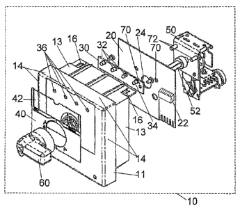
Figure 1 shows a module front 10 with an exemplary
configuration for a withdrawable module for an
electrical switchgear assembly, in an exploded
illustration.
The module front 10 shown is in this case an integral
part of the respective switchgear assembly module and
contributes to the formation of the module housing,
CA 02600549 2007-09-10
WO 2006/105881
PCT/EP2006/002764
- 6 -
The module front 10 comprises a front element 11 in the
form of a trough and having a trough base 12 and four
inner side walls 13 and four outer side walls 14. Inner
and outer side walls are arranged spaced apart from one
another and enclose an intermediate space for
accommodating the rest of the module housing. The
trough base 12, whose outer side forms the front face
of the module front 10, in this case has a virtually
rectangular cross-sectional area.
The module front 10 has, on its inner side walls 13,
means 16 which allow for the module front 10 to be
connected to the rest of the module housing, for
example in the form of cutouts in order to make it
possible for them to be latched with hooks of the rest
of the module housing, or vice versa. The module
housing and the module front in this case each have
complementary connecting means.
The module front 10 comprises an integrated control
device 20, which in this case is in the form, for
example, of a control board, 'via which control commands
and instructions from an external drive system can be
processed. The control device 20 or the control board
has at least one preconfigurable interface 22, via
which status details or status information relating to
the respective switchgear assembly module and/or the
operating means- controlled by the module can be made
available for callup.
The at least one preconfigurable interface 22 may in
this case be, in particular, an interface which can be
read by suitable data processing devices, for example
an RS-232, RS485/RS422 and/or a USB interface, but it
is also advantageously possible to provide conventional
power links or bus links, such as, for example, an
Ethernet interface, for reading the relevant status
information via a corresponding bus system or control
CA 02600549 2007-09-10
WO 2006/105881
PCT/EP2006/002764
- 7 -
system and/or via a local or global network. As an
alternative to this or in addition to this, at least
one interface for wireless information transmission to
a corresponding control system and/or a data processing
device set up for this purpose, for example by means of
wireless LAN (WLAN) or Bluetooth, can also be provided.
Furthermore, the module front 10 has an integrated
display device 30, which is in the form of an LED board
and which, by accessing the control device .20, visually
displays status information relating to the
withdrawable module and/or the operating means
controlled by the withdrawable module. The LED board 30
in this case comprises a plurality of monochromatic
LEDs 32 and/or at least one multicolored LED 34 in
order to display relevant status information in color-
coded fashion.
In addition to the visual display of status
information, an acoustic display of predetermined
status information can also be provided, for example by
means of an acoustic signal transmitter which emits a
corresponding acoustic signal when a certain state is
reached, in particular when there is a functional
failure or a functional fault in the respective module
and/or in the operating means controlled by the
respective module.
Provided in the trough base 12 of the trough-like
module front 10 are cutouts 36 and/or at least one
viewing window, through which it is possible to see
, into the LEDs 32, 34 of the LED board 30 from the
trough base outer side, i.e. from the front panel 15 of
the module front 10.
Furthermore, an adhesive label 40 with an integrated
label carrier 42 for accommodating an insert label
which can be written on freely is provided on the
CA 02600549 2007-09-10
WO 2006/105881
PCT/EP2006/002764
- 8 -
trough base outer side 15, i.e. the front part of the
module front 10.
In addition, the module front 10 comprises a locking
unit 50, in particular a mechanical withdrawable-part
locking means which is operatively connected to a
rotatably mounted locking toggle 60 and/or master
switch or functional switch arranged on the front panel
15, for example via a shaft 52 and a correspondingly
designed transmission. Accordingly, when the switchgear
assembly module is activated, locking of the switchgear
assembly module in the switchgear cabinet is brought
about via the module front 10 by the withdrawable-part
locking means 50 and the module is secured against
removal during operation. At the same time, the
corresponding operating states such as test, ON, OFF
and the position of the withdrawable part, such as
inserted, isolated position, withdrawable part removed,
for example, are passed on.
Starting from the trough base 12, first the display
device 30, i.e. the LED boara, then the control device
20, i.e. the control board, and finally the locking
unit 50, i.e. the mechanical withdrawable-part locking
means, are located within the module front 10 or the
trough 12, 13 formed by the module front 10.
In order to allow for an operative connection between
the locking toggle 60 and the locking unit 50, the
control board 20 has at least one cutout 24 for passing
through a shaft 52.
Installation aids are provided in the form of a further
cutout 70 and screws 72 both on the mechanical locking
unit, the control board and the LED board.
Figure 2 shows the module front 10, with the exemplary
configuration shown in figure 1, in the view from
CA 02600549 2007-09-10
WO 2006/105881
PCT/EP2006/002764
- 9 -
below, the locking toggle GO, the trough-like front
element 10 and the mechanical withdrawable-part locking
means 50 being indicated.
Figure 3 shows the module front 10, with the exemplary
configuration shown in figure 1, in the front view,
i.e. in the viewing direction onto the front face 15 of
the module front 10. The front face 15 of the module
front 10 shows the four LEDs 32, 34 of the LED board
30, the locking toggle/toggle switch GO, and/or the
master switch as well as the adhesive label 40 with the
integrated label carrier 42, which is provided for
accommodating an insert label which can be written on
freely. The adhesive label 40 has a plurality of
pictograms 44 in the region around the locking
toggle/toggle switch GO, which pictograms correspond to
the respectively selected function and/or the
respective operating state of the switchgear assembly
module.
Figure 4 shows the module front 10, with the exemplary
configuration shown in figui'e 1, in a plan view, the
locking toggle 60, the trough-like module front 10 and
part of the mechanical withdrawable-part locking means
50 being indicated. The remaining components are hidden
by the side walls.
Figure 5 shows the module front 10, with the exemplary
configuration shown in figure 1, in a lateral sectional
view. The section plane A-A and viewing direction on
this plane are indicated in figure 4 by the markings A
and the associated arrows. Figure 5 indicates the
arrangement and sequence of the locking toggle 60, the
trough-like module front 10 with the LED board 30, the
control board 20 and the mechanical withdrawable-part
locking means 50.