Note: Descriptions are shown in the official language in which they were submitted.
CA 02600723 2007-09-12
WO 2006/105243 PCT/US2006/011546
Design Tool for Identifying Project Energy Interdependencies
BACKGROUND OF THE INVENTION
1. Field of the Invention
The present invention relates to a tool for modeling and optimizing
design parameters for a pulsed boring system.
2. Discussion of Related Art
There currently are systems for modeling and aiding in design of
various systems. The models are very specific and developed to mimic a
certain system. Since they only model the system for which they were
developed, a new model must be developed for each new system.
There appear to be no models developed for a pulsejet boring
system employing underground combustion of energetic fluids.
Therefore, any prior art models would not apply to the current system to
be modeled, and would require manual selection of parameter values to
find an optimum set.
This becomes very time-consuming and tedious with no guarantee
that an optimum parameter set will be determined.
Models also used to determine if a given set of parameters values
will result in a functional unit.
Since there are no models developed for the above-mentioned
system, functionality may be determined by creating prototypes of
various design parameters and testing them.
This can become very expensive with no guarantee that the
systems will function.
-1-
CA 02600723 2007-09-12
WO 2006/105243 PCT/US2006/011546
Currently, there is a need for a modeling system for determining
optimized design parameters for a pulsejet boring system employing
combustion of energetic fluids.
SUMMARY OF THE INVENTION
One embodiment of the present invention is a system [200] for
modeling the energy of an energetic fluid pulsejet boring system
comprising:
a. a fluid flow energy unit [251] for receiving an indication of
fluid volume and mission duration and for calculating fluid flow
energy from its inputs;
b. an exhaust and retention energy ("EARE") unit [253] for
receiving an indication of exhaust gas volume and mission
duration as inputs and for calculating exhaust and retention
energy from its inputs,
c. a comminuting energy unit [255] for receiving an indication of
hole diameter and specific energy of rock intended to be bored
as inputs, and calculating comminuting energy form its inputs,
d. a total energy unit [257] for receiving the fluid flow energy
from the fluid flow energy unit [251], the exhaust and retention
energy from the EARE unit [253], and the comminuting energy
from the comminuting energy unit [255], to calculate an
estimate of total energy of said energetic boring system.
Another embodiment of the present invention is a method of
optimizing parameters of an energetic pulsejet boring system constrained
by project requirements and a maximum total energy restriction,
comprising the steps of:
-2-
CA 02600723 2007-09-12
WO 2006/105243 PCT/US2006/011546
a) receiving defined system inputs [5031;
b) receiving a maximum allowable energy, "Emax" [5051;
c) receiving said project requirements defining acceptable ranges of a
plurality of system parameters [507];
d) determining an integrated set of parametric equations modeling
the total energy of the system in terms of said system parameters;
e) calculating a solution set of entries each having system parameter
values for each total energy value of the system, over a plurality of
system parameter values, using the defined system inputs;
f) locating minimum energy points ("MEP") [513] in the solution set;
g) if the values of parameters at an MEP are not within the acceptable
ranges [515], then selecting the parameters values to move away
[5171 from the MEPs until parameters are encountered which meet
said project requirements;
h) if no entries are encountered before the energy of the system
reaches Ema,, [523], then indicating that there is no acceptable
design solution based upon the given inputs [525].
Still another embodiment of the present invention is a method of
determining the system parameters values of a pulsejet boring system
having a defined mission duration, hole depth, hole diameter, rock
density, fluid energy density, fluid density, for a particular drilling
methodology creating a specific particle size, comprising:
a. receiving an acceptable ranges [507] of hole size, penetration rates,
and total energy of the system;
b. creating an integrated set of parametric equations [509] in which:
i. comminuting energy is a function of hole depth, hole diameter
and specific energy of rock;
-3-
CA 02600723 2007-09-12
WO 2006/105243 PCT/US2006/011546
ii. exhaust & retention energy is a function of exhaust gas volume
and mission duration;
iii. fluid flow energy is a function of fluid volume and mission
duration,
iv. total energy as the sum of comminuting energy, exhaust and
retention energy, and fluid flow energy;
c. calculating total energy entries [513] for various hole sizes and
penetration rates as a solution set;
d. determining [515] if the solution set has entries with a hole size,
penetration rate and total energy within the acceptable ranges
received in step "a" above; and
e. using parameter values of the solution set entries within the
acceptable ranges as the system parameter values for optimizing
the system.
OBJECTS OF THE INVENTION
It is an object of the present invention to provide a system for
determining if a pulsejet boring system is feasible using a given design
parameter values.
It is an object of the present invention to provide a system for
automatically determining design parameters for a pulsejet boring
system.
It is another object of the present invention to provide a system for
automatically optimizing selected design parameters of a pulsejet boring
system.
-4-
CA 02600723 2007-09-12
WO 2006/105243 PCT/US2006/011546
BRIEF DESCRIPTION OF THE DRAWINGS
The advantages of the instant disclosure will become more
apparent when read with the specification and the drawings, wherein:
FIG. 1 is a perspective view of a system to be modeled having a
ground unit employing a pulsejet boring head.
FIG. 2 is an enlarged perspective view of the pulsejet boring head
of the system of FIG. 1.
FIG. 3 is a schematic block diagram of one embodiment of an
energy simulation system according to the present invention for modeling
and optimizing the system shown in FIG. 1.
FIG. 4 is a schematic block diagram of a feedback loop of the
simulation system of FIG. 3.
FIGs. 5a and 5b together represent a flowchart illustrating
functioning of one embodiment of the present invention.
DETAILED DESCRIPTION OF THE INVENTION
When modeling a system, the fundamental interrelationships
between component parts are studied, as well as the consequences of
each design choice on all other parts of the system.
FIG. 1 is a perspective view of a system to be modeled having a
ground unit employing a pulsejet boring head.
Ground unit 100 is placed on the ground just above a target 1
which may be an underground void or object. Ground unit 100 may be
delivered there by a number of different conventional known methods.
-5-
CA 02600723 2007-09-12
WO 2006/105243 PCT/US2006/011546
Ground unit 100 employs a platform subsystem 1000 having
retention and orientation devices 1500 which secure ground unit 100 to
the ground and tilts platform 1000 to an optimum orientation for boring
to target 1. Platform subsystem 1000 is designed to hold, store and
carry all the equipment during deployment, initiate boring of an access
hole, hold materials to be used in a fuel reservoir, stabilize ground unit
100 for boring, and communicate with other units.
A boring subsystem 3000 employs at least one pulsejet which
bores down through the ground toward target 1, creating an access hole
5. Boring subsystem 3000 is designed to create pulse explosions forcing
liquid slugs to impact material s (rock) to be bored. The exhaust gases
force the excavated materials out of the access hole 5 and to the surface.
Boring subsystem 3000 is connected to platform subsystem 1000
by an umbilical subsystem 2000.
Umbilical subsystem 2000 also employs mechanical actuators and
exhaust gas retro-jets to provide retention forces produced during boring,
as well as for steering and advancing umbilical subsystem 2000 and
boring 3000 subsystems deeper into the access hole 5.
FIG. 2 is a perspective view of one embodiment of a boring
subsystem 3000 according to the present invention. The end of the
boring subsystem 3000 is a boring head 3200 containing ten to twenty
pulsejets 3100. Pulsejets 3100 receive energetic fluid 7, and cause the
fluid to create a rapidly expanding bubble forcing portions of the fluid
out of a nozzle 3260 at high speeds as a plurality of fluid slugs 10. Since
the fluid used is highly incompressible, the impact of slugs 10 bores
through rock and earth.
-6-
CA 02600723 2007-09-12
WO 2006/105243 PCT/US2006/011546
Energetics
Energy simulations require the reduction of each logical
component of the boring system 10 to an energy transaction. A critical
component of this type of design is to identify the interdependencies of
the system.
A pulsejet design utilizes chemical energy stored on platform 1000
and an energetic fluid delivery system, umbilical 2000 and boring head
3200.
The energy balance simulation investigates the energy required to
accomplish the task, and should include all sources of energy and all
energy requirements. The total energy stored on platform (1000 of FIG.
1) must equal or exceed the energy required.
The system energies are co-dependent. For example, a design
change that increased the energy density of the fluid would be shown to
require a concurrent increase in the fluid density of the exhaust and the
cross-sectional area devoted to exhaust.
For example, the area of the umbilical is the sum of the areas
devoted to the delivery of supplies (fluids, electrical, etc.) to the
borehead,
the internal exhaust of rock and drilling fluids, control and
communications, steering and retention. But these areas themselves are
not independent. Consider the area devoted to internal exhaust.
Decreasing that area requires an increase in the area devoted to
retention (since the pressure developed at the borehead will increase as
will the frictional forces inside the tube). Ultimately, all of the
parameters and their interrelationships can be expressed
mathematically, and boundary conditions established which will lead to
a solution contained within the solution space.
-7-
CA 02600723 2007-09-12
WO 2006/105243 PCT/US2006/011546
A precise study of the energy conversion (or thermodynamics) of a
pulsejet system will establish boundary conditions on key physical
parameters, such as the mass density and energy density of the fluid.
The specific energy for rock removal is a function of fluid slug
energy, the mass ratio of fluid to rock is a function of fluid slug energy
and the exhaust and retention energies are functions of rock particle size
(which itself is based on the specific energy of rock removal, and
ultimately fluid slug energy).
System components that are independent of all other components
are top level, components dependent on only one other logical component
are the next level, and components dependent on several other
components are the lowest level.
This invention is a method and software system for modeling the
interdependencies of physical parameters to identify a workable set of
physical parameters. The parameters of the system include: exhaust gas
volume, rock density, cutting fluid energy density, physical density of
fluid, mission duration, fluid volume, fluid flow energy, hole depth, hole
diameter, drilling methodology, rock particle size, and the specific energy
of rock. Most of the values of these parameters are provided, whereas
others are calculated by the system.
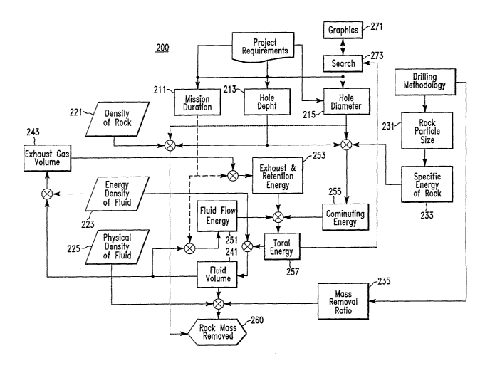
FIG 3 is a simplified schematic block diagram of a simulation
system according to the present invention. This is set up to model the
functioning the pulsejet boring system shown in FIGs. 1-2. This can be
modeled mathematically, or reduced to software which solves the
mathematical model. Separate subroutines may be modeled on separate
computing devices that are interconnected.
-8-
CA 02600723 2007-09-12
WO 2006/105243 PCT/US2006/011546
Therefore, the simulation system shown in FIG. 3 may be either a
mathematical model, a model implemented on a computer program or a
set of interconnected computing units which run software routines to
perform these functions.
The simulation system 200 seeks to map out the interdependencies
of the flow and conversion of energy. The physical properties of the fluid
are mapped in block 221, 223, 225. The system inputs are indicated by
blocks 211, 213, 215. System parameters which are dependent on only
one other parameter are in blocks 231, 233, 235.
Project requirements such as initial values of mission duration,
hole depth and hole diameter are received and stored by units 211, 213,
215, respectively.
The density of rock (the material which will be bored) is stored in
unit 221.
The energy density of fluid to be used is stored in unit 223. The
physical density of fluid used is stored in unit 225.
A drilling methodology is chosen. This is determined by the
method of drilling. They type of boring may be pulsed fluid, continuous
liquid jet, mechanical, etc. The boring chosen was pulsed liquid boring.
This type of boring has numerous options to be chosen regarding the
width of liquid slugs, the angle of the leading portion of the slug, the
number of liquid slug sources, their relative angles, the pulse rate,
intensity, etc. The drilling methodology determines the rock particle size
which is stored in unit 231.
The rock particle size determines the specific energy of the rock,
which is stored in unit 233.
-9-
CA 02600723 2007-09-12
WO 2006/105243 PCT/US2006/011546
The comminuting energy unit 255 determines the comminuting
energy from the hole diameter received from unit 215, the specific energy
of the rock received from unit 233 and the hole depth received from unit
213.
The energies of the rock particles, the exhaust gasses being
expelled from hole 5 to the surface, and the retention energy to hold
umbilical 2000 and boring head 3200 inside borehole 5 are determined
by Exhaust 8y Retention Energy unit 253. It receives an estimate of the
exhaust gas volume and the stored mission duration stored in unit 221.
A fluid flow energy unit 251 calculates the energy of passing the
fluid through the system. It receives an indication of fluid volume from a
fluid volume unit 241.
Fluid volume unit 241 receives an indication of total energy of the
systems and the energy density of the fluid being used, and calculates a
total fluid volume and provides it to fluid flow energy unit 251 and to
exhaust gas volume unit 243.
Exhaust gas volume unit 243 calculates the total exhaust gas
volume and provides the calculation to the exhaust & retention unit 253
as input.
Total energy unit 257 calculates the total energy of the system by
summing the energies from calculated by the fluid flow energy unit 251,
the exhaust & retention unit 253 and the comminuting unit 255.
The output of the total energy unit 257 is provided as input to fluid
volume unit 241.
Rock mass unit 260 calculates rock mass removed form the
physical density stored in unit 225, the system fluid volume from fluid
-10-
CA 02600723 2007-09-12
WO 2006/105243 PCT/US2006/011546
volume unit 241 and the mass removal ratio stored in mass removal unit
235. The mass removed ratio is determined by the drilling methodology
selected.
In one embodiment of the present invention, most parameters will
be defined and the solution set for the undefined parameter(s) will be
provided.
In this embodiment, a search unit 273 interactively varies at least
one input parameter, and determines the total energy from total energy
unit 257. Search unit 273 then receives and stores the solutions to
produce a solution set.
In one embodiment, a graphic unit 271 displays the solution set to
a user who visually determines a minimum energy point and then selects
values of the parameters near the energy point which satisfy other
requirements, such as a maximum system energy allowed. For example,
one may select hole diameter and mission duration (boring penetration
rate) as inputs to vary. The total system energy for various values of the
hole diameter and the mission duration is then graphed to produce a
surface. The user selects a low point on the surface, and if below a
maximum energy, defines hole diameter and mission duration which is
optimized relating to total energy.
In another embodiment of the present invention, a set of
parameters values to be tested are input to the system. The system then
identifies if the parameters are one of the solutions (is feasible).
In modeling this system, it was noted that there was a feedback
loop found which was isolated and shown in FIG. 4. As exhaust gas
volume 243 becomes larger, it increases exhaust energy. This, in turn,
increases the retention energy required to hold the umbilical in the
-11-
CA 02600723 2007-09-12
WO 2006/105243 PCT/US2006/011546
access hole 5. These two energies are calculated by Exhaust and
Retention unit 253. This increased energy increases the total energy
calculated by total energy unit 257.
Since the total energy required has increased, the total fluid
volume required will increase in unit 241. This, in turn increases the
exhaust gas volume 243.
Unchecked, this system will constantly increase to infinite total
system energy and infinite fluid volume required. Adjustments to the
mission duration in unit 211 and energy density of the fluid in unit 223
act as controls to slow or keep the system from becoming unstable.
FIGs. 5a and 5b together represent a flowchart illustrating
functioning of one embodiment of the present invention.
Process starts at step 501. In step 503, defined inputs are
provided to the system.
In step 505, a maximum acceptable system energy is provided to
the system.
Acceptable parameter vale ranges defined by the project
requirements are provided to the system in step 507.
In step 509 parametric equations of the energies of the system are
developed. As described above, these equations are interdependent.
In step 511, the values of at least one parameter are varied over a
range and the equation sets are solved to determine total system energy.
Each set of parameter values and the corresponding energy are stored as
an entry in the solution set.
-12-
CA 02600723 2007-09-12
WO 2006/105243 PCT/US2006/011546
In step 513 the solution set is analyzed define the minimum energy
points (MEPs).
In step 515 the parameter values of an MEP are initially used as
the current parameter values being tested. The current parameter values
are tested against the acceptable ranges. If so ('yes"), the current
parameter values are used in the design of the boring system in step
519, and processing stops in step 521.
If the current parameter values do not fall within the acceptable
ranges ("no"), then new current parameter values are selected in step
517, moving away from those of the MEPs.
Processing that continues in step 523 of FIG. 5b. In this step it is
determined if the total energy of the current parameter values being
tested are at or below the maximum acceptable system energy. If so
("yes"), processing continues that step 515 of FIG. 5a.
If the total energy of the of the current parameter values being
tested is above the maximum acceptable system energy ("no") then a
message is provided in step 525 indicating that the system is not feasible
with the set of parameter values used, and processing stops at step 521
of FIG. 5a.
In an alternative embodiment of the present invention as shown in
phantom, it is determined which inputs may be varied to search for a
solution. For example, the energy density of the fluid or the mission
duration, which were initially determined to be fixed, may now be varied
in step 529. Processing then continues with the modified inputs at step
511.
Even though the above description focused on providing values for
certain input parameters and solving for other parameters for illustration
-13-
CA 02600723 2007-09-12
WO 2006/105243 PCT/US2006/011546
purposes, it is within the scope of this invention to provide different
input and to solve for other parameters. Since this is a multi-variable
interactive system, any may be changed to cause the remainder of the
system to change accordingly.
Since other modifications and changes varied to fit particular
operating requirements and environments will be apparent to those
skilled in the art, the invention is not considered limited to the example
chosen for the purposes of disclosure, and covers all changes and
modifications which do not constitute departures from the true spirit and
scope of this invention.
-14-