Note: Descriptions are shown in the official language in which they were submitted.
WO 2006/099067 CA 02600841 2007-09-10PCT/US2006/008464
TITLE
Catheter with Larger Diameter Proximal End Portion
The invention relates to medical devices and more particularly to catheters
and catheter
assemblies.
Catheter assemblies, and particularly catheter assemblies for use in
hemodialysis, are known
that have one, two or more lumens extending from a distal end to a proximal
end, where the distal
end is placed in a blood vessel of a patient, such as the jugular vein, with
the proximal end
extending from the patient for each lumen to be connected to a respective
conduit of a hemodialysis
machine. Customarily, each lumen of the catheter assembly is first connected
to a respective
extension tube within a hub body, and the extension tube is terminated in a
luer connector to
facilitate connection with and disconnection from the conduit of the
hemodialysis machine and
commonly the extension tube has disposed therealong a clamp, such as a Roberts
clamp, for
temporarily closing the conduit when necessary. Implanted catheter assemblies
are connected to
medical apparatus such as hemodialysis apparatus through the luer connectors,
and then
disconnected therefrom, all through many cycles; such connection and
disconnection involves the
catheter assembly undergoing many cycles of stress and strain especially
focused at the proximal
end where the catheter proximal end enters the hub which connects the catheter
lumens to
respective extension tubes, or where a single lumen catheter enters its luer
connector directly
instead of via a hub and extension tube.
It is desired to provide an assurance against occluding or kinking of the
catheter lumens, as
well as greater strength, at the connection of the catheter and the hub, or at
the connection of a
single lumen catheter luer connection where no hub is utilized.
1
WO 2006/099067 CA 02600841 2007-09-10 PCT/US2006/008464
Certain catheter assemblies, termed PICC catheters (for peripherally inserted
central
catheters), are implanted through a vessel entry on an arm of the patient,
known as axillary
placement. But, usually, the catheter assembly is secured to the torso of the
patient in a manner to
prevent any dislocation of the distal tips of the catheter lumens from any
movement along the vessel
after initial placement at the catheterization site. This manner of securement
is usually
accomplished by a process termed tunneling, in which the proximal portion of
the catheter assembly
outside of the vessel is tunneled subcutaneously near the vessel entry site,
typically beneath the
clavicle of the patient, whereafter the hub is sutured or otherwise secured to
the patient. By this
process, during the connection with and disconnection from the hemodialysis
machine of the
extension tubes, there is no stress or strain passed to the distal end of the
catheter assembly that
might tend to dislodge the distal lumen tips from the desired location along
the vessel.
The orientation of the tunneled portion of the catheter assembly is not
axially aligned with
the distal portion of the catheter assembly and in fact a relatively sharp
bend may be made in the
catheter assembly distally of the tunneled portion during placement.
It is desired to provide an assurance against occluding or kinking in the
sharp bend between
the tunnel's distal end and the venotomy.
When a catheter is being inserted vascularly into a patient, and the incision
is made into the
vessel at the access site or venotomy, and the introducer sheath is placed to
maintain open the
vascular access site for introduction of the catheter assembly, the catheter
assembly is initially
inserted along the guide wire through the introducer sheath. During this
process, aspiration of
blood occurs and measures must be taken to temporarily stop the flow, such as
manually closing off
the proximal end of the introducer sheath. But as the catheter is inserted
into the sheath, additional
blood again begins to extrude from the sheath.
2
CA 02600841 2012-08-20
It is desired to provide a means for minimizing the flow of blood as the
catheter
assembly is inserted through the introducer sheath and into the vessel, and
also after
catheter insertion as the introducer sheath is removed from the access site.
Catheters are conventionally produced in various sizes depending on desired
uses,
and their outer diameters are measured in units termed "french" or "F", with
one F
equaling 0.013 inches or 0.32 millimeters. The largest sized catheters
utilized for vascular
placement may have an outer diameter of about 17 F, while the smallest sized
dual-lumen
catheters presently preferred are 5 F although smaller sized single lumen
catheters are
known. Certain problems are associated with catheters after they are
vascularly in a
patient; for example, development of phlebitis and thrombosis is known when
the
catheter outer diameter is almost the same size as the inner diameter of the
vessel within
which it is implanted.
It is desired to provide a catheter with a very small outer diameter,
especially a
dual lumen catheter, thereby minimizing the tendency of phlebitis or
thrombosis or the
like, to develop.
In accordance with an aspect of the present invention, there is provided, in
combination, an introducer sheath and catheter. The introducer sheath has a
proximal
end opening having an inner diameter and the catheter including a catheter
body having a
distal end and a proximal end with a lengthy distal portion of the catheter
body having a
constant outer diameter, and a lengthy proximal portion tapering from a larger
outer
diameter to a smaller outer diameter in a direction beginning at the proximal
end of the
catheter body and extending toward the distal portion. The proximal portion
includes a
diameter therealong greater than the inner diameter of the sheath proximal end
opening
such that upon at least partial insertion of the catheter body through the
introducer sheath
the proximal portion closes off the proximal end opening of the introducer
sheath
The accompanying drawings, which are incorporated herein and constitute part
of
this specification, illustrate the presently preferred embodiments of the
invention, and,
3
=
CA 02600841 2012-08-20
together with the general description given above and the detailed description
given
below, serve to explain the features of the invention. In the drawings:
present invention; Fig. 1 is a top plan view of a multi-lumen catheter
assembly according to the
Fig. 2 is an enlarged sectional view of the lumens of the multi-lumen catheter
assembly taken along lines 2 ¨ 2 of Fig. 1;
Fig. 3 is an enlarged sectional view of the lumens of the multi-lumen catheter
assembly taken along lines 3 ¨ 3 of Fig. 1;
Fig. 4 is a cross-sectional view of the catheter inserted into the introducer
sheath
during patient placement;
Fig. 5 is a cross-sectional view of the catheter proximal end fully inserted
adjacent
the vascular incision after sheath removal; and
4
WO 2006/099067 CA 02600841 2007-09-10PCT/US2006/008464
Fig. 6 is an isometric view of an alternate embodiment of the present
invention with a longer
larger diameter proximal catheter section implanted and subcutaneously
tunneled in a patient.
In the drawings, like numerals indicate like elements throughout. Certain
terminology is
used herein for convenience only and is not to be taken as a limitation on the
present invention.
The terms "distal" and "proximal" refer, respectively, to directions closer to
and farther away from,
respectively, an insertion end of the catheter of the present invention. The
terminology includes the
words specifically mentioned, derivatives thereof and words of similar import.
The embodiments
illustrated below are not intended to be exhaustive or to limit the invention
to the precise form
disclosed. These embodiments are chosen and described to best explain the
principle of the
invention and its application and practical use and to enable others skilled
in the art to best utilize
the invention.
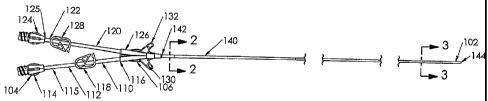
Referring now to Fig. 1, a catheter assembly 100 according to the present
invention is
shown, having a distal end 102 and a proximal end 104. While catheter assembly
100 is shown and
described as having two lumens, the present invention also is beneficial to
single lumen catheters or
catheters with more than two lumens. A hub 106 connects the distal end 102 and
the proximal end
104, and the proximal end 104 includes first and second extension tube
assemblies 110, 120,
respectively. The first extension tube assembly 110 includes an extension tube
112 having a luer
connection 114 fixedly connected to a proximal end 115 of the extension tube
112. A distal end
116 of the extension tube 112 is fixedly connected to the hub 106. A clamp
118, such as a Roberts
clamp, is disposed over the extension tube 112 between the proximal end 115
and the distal end
116.
The second extension tube assembly 120 includes an extension tube 122 having a
luer
connection 124 fixedly connected to a proximal end 125 of the extension tube
122. A distal end
5
WO 2006/099067 CA 02600841 2007-09-10PCT/US2006/008464
126 of the extension tube 122 is fixedly connected to the hub 106.. The clamp
128 is disposed over
the extension tube 122 between the proximal end 125 and the distal end 126.
The hub 106 fluidly
connects the extension tube assemblies 110, 120 with the distal end 102 of the
catheter assembly
100. The hub 106 includes suture wings 130, 132 that are used to suture the
hub 106 to a patient's
skin after insertion.
The distal end 102 includes a dual lumen catheter 140 that includes a proximal
end 142 that
is fixedly connected to the hub 106 and a distal end 144 that is inserted into
vasculature of a patient.
As can be seen from Figs. 2 and 3, the catheter 140 has a generally circular
cross section. The
catheter 140 tapers from a larger diameter to a smaller diameter in a proximal
to distal direction,
meaning that the catheter 140 is thicker proximate to the hub 106 than at the
distal end 144.
Preferably, the catheter has a tapered proximal portion that extends from the
larger diameter
adjacent the hub for about from 5 cm to 15 cm, and preferably about 10 cm,
whereafter the catheter
diameter is constant extending to the distal end portion, which also may be
tapered to an even
smaller distal tip diameter, or have spaced distal tips for the respective
lumens. Typical diameters
for one particular useful embodiment of the catheter of the present invention,
for use with
peripherally inserted central catheters, or PICCs, are that the general
diameter of the catheter is less
than 5 F, such as about 4 F, and the larger diameter adjacent the hub is about
7 F; and where the
general diameter is 3 F, the larger diameter is about 4 F; wherein with such
small diameters the
catheter would be less prone to inducing phlebitis or thrombosis or the like.
Referring to Figs. 1 to 3, the catheter 140 includes a first lumen 150 that
fluidly
communicates with the first extension tube 110 through the hub 106 and a
second lumen 160 that
fluidly communicates with the second extension tube 120 through the hub 106.
The first lumen 150
and the second lumen 160 are each generally rounded within the catheter 140.
While the catheter
6
WO 2006/099067 CA 02600841 2007-09-10 PCT/US2006/008464
140 tapers along its length, the diameters of each of the lumens 150, 160
remain, within
manufacturing tolerances, constant.
The generally rounded lumens 150, 160 enhance fluid flow through the catheter
140 and
eliminate corners which encourage blot clotting within the lumens. Preferably,
the lumens 150, 160
are sized to allow a 0.018" guide wire to pass with minimal resistance through
either lumen 150,
160, such as having diameters of between 0.020 in and about 0.025 in or 0.030
in. A septum 146
separates the first and second lumens 150, 160. Nearer to the proximal end 142
of the catheter 140,
the septum 146 is shown as being thicker than nearer to the distal end 144 of
the catheter 140. The
septum 146 is preferably centered throughout the catheter 140.
The larger diameter of the catheter 140 at the proximal end 142, along with
the constant
diameter of the lumens 150, 160 housed within the catheter 140, reduces the
likelihood of kinking
of the lumens 150, 160 nearer to the proximal end 142, especially during
handling when the
proximal end luer connectors are connected to or disconnected from medical
apparatus such as
hemodialysis apparatus or the like, while just distally of the hub 106 the
catheter 140 enters the
subcutaneous tunnel (see Figs. 4 to 6) and thus is held fixed in position.
In Fig, 4, a catheter assembly 200 is shown, wherein its tapered proximal end
portion 202 is
entering the proximal end 204 of an introducer sheath 206 during vascular
insertion of the catheter
distal portion 208, which is mostly already in the vessel 210 with the use of
a guide wire 214,
entering at venotomty or vascular incision 212. It is seen that the proximal
end portion 202 has been
inserted until at some location along the tapered portion the proximal end
portion 202 has filled the
proximal opening 216 of the introducer sheath 206, thus closing off the
opening 216 to stop any
aspiration of blood therethrough. At this point, the introducer sheath may
begin to be split
manually along longitudinally extending opposed frangible sections or
weaknesses such as grooves
7
WO 2006/099067 CA 02600841 2007-09-10 PCT/US2006/008464
(not shown) as the catheter is continuously urged distally to continue to
close off the remaining
unsplit portion of the sheath, and so on until the sheath is fully split apart
and discarded.
Similarly, in Fig. 5, catheter assembly 200 is shown after introducer sheath
206 of Fig. 4 has
been split and removed from about the catheter, and the catheter assembly has
been implanted fully
into the vessel 210 and the guide wire 214 removed. The proximal end portion
202 has now
become moved to be adjacent and partially into the vascular incision 212, and
is seen to
substantially plug and close off the vascular incision.
Figure 6 illustrates an alternate embodiment of the present invention.
Catheter assembly
300 is shown implanted and subcutaneously tunneled in a patient. Catheter 302
has a lengthy distal
portion 304 with an outer diameter appropriate for the vessel of the patient,
and a lengthy proximal,
tunneled portion 306 with a generally constant greater diameter from the hub
308 through the tunnel
310 and about the sharp bend 312, where it tapers at transition 314 to a
smaller outer diameter
entering the venotomy 316 and extending to its distal end 316. The larger
diameter portion at bend
312 is more resistant to occlusion and kinking than if it Were of the smaller
diameter that is
vascularly implanted. Catheter 302 may include a proximal end portion 320 with
an even greater
outer diameter adjacent to hub 308, if desired. For example, for a catheter
having an outer diameter
of 10 F within the vessel, the larger diameter of proximal portion 304 may be
of 12 F, and the
proximal end portion 320 may enlarge in a taper from 12 F to 13 F or 14 F.
8