Note: Descriptions are shown in the official language in which they were submitted.
CA 02600918 2007-08-28
WO 2006/089431 PCT/CA2006/000293
-1-
TITLE: METHOD AND APPARATUS FOR NON-INVASIVE MEASUREMENT
OF SKIN TISSUE CHOLESTEROL
[0001] This application claims the benefit of U. S. Provisional
Application No. 60/656,381 filed February 28, 2005, and the entire contents of
which are hereby incorporated by reference.
FIELD OF THE INVENTION
[0002] The present invention relates to a method and apparatus for
non-invasive measurement of skin or skin tissue cholesterol. More
particularly, the invention relates to the direct assay of cholesterol in skin
samples, typically without using instrumentation, and as such is suitable for
self-testing. In particular, one aspect of the invention provides for a device
to
apply a detector reagent to a selected area of skin. Another aspect of the
invention provides for an indicator device to produce a visual change
corresponding to the amount of detector reagent that is bound in the skin.
BACKGROUND OF THE INVENTION
[0003] Identifying people with high skin cholesterol is useful in
determining individuals at risk of either having or developing atherosclerosis
as well as those at risk of having similar or other diseases attributable to
high
cholesterol levels.
[0004] Coronary artery disease caused by atherosclerosis remains the
number one cause of morbidity and mortality in North America and many
other parts of the world. Prevention and intervention requires the cost
effective identification of those individuals not only having the disease but
also
those at risk of developing the disease. Therefore, there is currently much
interest in determining levels of marker molecules that are able to predict
risk
of atherosclerotic disease.
[0005] Measurement of blood plasma total cholesterol levels is one of
the most widely used methods to determine risk of atherosclerosis. However,
CA 02600918 2007-08-28
WO 2006/089431 PCT/CA2006/000293
-2-
plasma total cholesterol levels alone do not accurately predict risk and
better
results have been obtained through measurement of plasma lipoproteins.
Measurement of cholesterol in both low density lipoprotein (LDL) and high
density lipoprotein (HDL) show advantages over measuring total cholesterol
levels. All of these measurements require blood sampling after a long period
of fasting so that dietary cholesterol does not interfere. Additionally, the
sampling can be uncomfortable and carries some small risk of infection.
Furthermore, the analysis often requires complicated and expensive
equipment.
[0006] One example of a device that allows a user to obtain a blood
cholesterol level is shown in U. S. patent no. 5,340,539. This patent
circumvents some of the problems associated with visits to a doctor or clinic
and makes fasting more convenient. However, a blood sample obtained from
a finger prick with a lancet device is still required, which can be
objectionable
to many individuals.
[0007] In many cases, however, the levels of plasma cholesterol and
lipoproteins do not correlate with the extent of atherosclerotic disease. It
is
therefore desirable to assay other marker molecules that reflect the extent of
atherosclerosis and provide a risk assessment of cardiovascular disease.
[0008] For example, significant amounts of cholesterol occur in tissue
in addition to that found in plasma and increased levels in tissue have been
shown to play a major role in development of atherosclerosis. It has been
demonstrated that the accumulation of cholesterol in tissues, including the
skin, correlates closely with the amount of cholesterol found in arterial wall
deposits. The measurement of cholesterol in skin, therefore, may reflect the
extent of atherosclerosis. Indeed, cholesterol levels in skin biopsy samples
have been shown to correlate with arteriosclerosis and to provide a risk
assessment for patients with ischemic cardiac disease (Bouissou H., De
Graeve J., et al. Ann. Biol.Clin. Vol 40, 364-365, 1982). Also, measurement of
cholesterol extracted from lyophilized skin biopsy samples correlates with
CA 02600918 2007-08-28
WO 2006/089431 PCT/CA2006/000293
-3-
serum lipid quotient in normals and in patients with ischemic cardiac disease
(Y.P. Nikitin et al. Kardiologiia, II, 48-51, 1987).
[0009] A drawback of obtaining skin biopsy samples for skin cholesterol
riPtPrminatinns for risk assessment of atherosclerosis is that there can be
pain
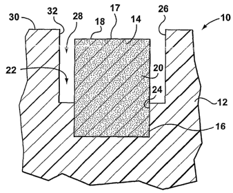
in obtaining the skin samples. Moreover, a risk of infection at the biopsy
site is
possible. Obtaining the skin samples typically requires trained professionals.
In addition, such samples contain subcutaneous fat and several layers of skin,
some of which are highly vascularized. Consequently these samples contain
heterogeneous sources of cholesterol and do not give reproducible and
reliable cholesterol assay results.
[0010] One method for assaying various substances in the blood
directly below the surface of the skin or on its surface is described in U. S.
patent no. 4,458,686. This patent is based on electrochemical measurement
of generated oxygen concentrations. For non-volatile substances that do not
diffuse through the skin, however, it is necessary to implant enzymes under
the skin to effect oxygen changes at the skin surface. The patent discloses
the use of the enzyme cholesterol oxidase to determine cholesterol but it
appears that it is blood cholesterol rather than skin cholesterol that is
being
measured.
[0011] Consequently, there is a need for a simple method and
apparatus for non-invasive measurement of cholesterol in the skin that is
unaffected by other sources of cholesterol.
SUMMARY OF THE INVENTION
[0012] The present invention provides a method and apparatus for non-
invasive measurement of skin cholesterol. More particularly, one aspect of the
invention provides for a device to apply a detector reagent to a selected area
of skin. Another aspect of the invention provides for an indicator device to
produce a visual change corresponding to the amount of detector reagent that
is bound in the skin. The method and apparatus of this invention typically do
CA 02600918 2007-08-28
WO 2006/089431 PCT/CA2006/000293
-4-
not require any instrumentation for certain embodiments, allowing the
invention to be suitable for self-testing, for example, but not limited to, in
the
home environment. As such the invention is particularly useful to allow
individuals to assess their risk of atherosclerosis and related vascular
diseases.
[0013] In one aspect of the invention, a method of measuring skin
cholesterol is provided, the method comprising:
a) appiying a detector reagent to a selected area of skin to bind
to cholesterol present in the skin;
b) applying an indicator surface to the selected area of skin, the
indicator surface having a solution that reacts with the detector reagent when
the indicator surface is in contact with the selected area of skin, the
reaction
to produce a visual color change corresponding to the amount of detector
reagent bound to cholesterol in the skin; and
c) analyzing the color produced on the indicator surface to
obtain a measurement of skin cholesterol.
[0014] The detector reagent can be applied to the selected area of skin
using capillary action. In a preferred embodiment of the invention the
detector
reagent is applied to the selected area of skin by at least one wicking
element.
The wicking element can be saturated with detector reagent. In a preferred
embodiment of the invention the wicking element is retained by a suitable
applicator.
[0015] Moreover, the wicking element can deform a controlled amount
to release the detector reagent.
[0016] The detector reagent concentration can be chosen so that a
visual color change occurs in step b) when the cholesterol present in the skin
is over a pre-selected threshold.
[0017] Further, the method can comprise applying the detector reagent
by applying a control detector reagent and a test detector reagent to two
CA 02600918 2007-08-28
WO 2006/089431 PCT/CA2006/000293 - -
-5-
separate areas of skin within the selected area of skin. The control detector
reagent is a higher concentration of the test detector reagent. For this
aspect,
the test detector reagent concentration is chosen so that a visual color
change
occurs in step b) when the cholesterol present in the skin is over a pre-
selected threshold.
[0018] Moreover, the method further comprises after step a) and before
step b) removing any excess detector reagent not bound to the cholesterol in
the skin. The excess detector reagent can be removed by a suitable
absorbent media.
[0019] In addition, the indicator surface can include a substrate solution
that reacts with a reporter component within the detector reagent. The
indicator surface can be a pad of absorbent material saturated with a
substrate solution, the substrate solution to react with the reporter
component
within the detector reagent.
[0020] Further, the method can comprise analyzing the color produced
is by a reflectance spectrophotometer. Alternatively, the color produced is
analyzed using a color comparator, such as, for example, but not limited to, a
graded series of color bands.
[0021] In another aspect of the invention, a device to apply a detector
reagent to a selected area of skin is provided, the device comprising:
a) a body; and
b) at least one applicator retained at one end thereof by the
body and having a second end to contact a selected area of skin, the second
end of the applicator to transfer to the selected area of skin a detector
reagent.
[0022] The applicator preferably applies the detector reagent to the
selected area of skin using capillary action. In one aspect the applicator
includes a wicking element.
CA 02600918 2007-08-28
WO 2006/089431 PCT/CA2006/000293
-6-
[0023] The body of the device can include at least one recess therein
for receiving the one end of the wicking element. The recess is of a depth
sufficient to receive therein the wicking element so that the second end of
the
wicking element does not extend beyond depth of the recess. Moreover, in a
preferred embodiment of the invention, the perimetrical extent of a portion of
the recess is greater than the perimetrical extent of the wicking element. The
portion of the recess having the greater perimetrical extent surrounds the
second end of the wicking element, preferably so that a gap is provided
therearound.
[0024] In a preferred embodiment of the invention, the wicking element
is a fiber plug. The wicking element can also be of inert polyolefin material.
[0025] Alternatively, the applicator can be a gel.
[0026] It is preferable that the applicator be cylindrical, however, where
two applicators are provided, the applicators can be spaced from one another
so that one applicator applies a control detector reagent and the second
applicator applies a test detector reagent, and each applicator can present a
different cross section at the second (or upper) end.
[0027] The applicator can be saturated with the detector reagent.
[0028] In a further aspect of the invention, an indicator device to
produce a visual color change corresponding to an amount of detector
reagent that is bound to cholesterol in the skin is provided. The indicator
device comprises an indicator surface provided by a body of the device so
that the indicator surface can contact a selected area of skin, the indicator
surface containing a sufficient amount of a solution that reacts when
contacted with a detector reagent that is bound to cholesterol in the selected
area of the skin to produce a visual color change to at least a portion of the
indicator surface.
[0029] The solution can be a substrate solution that reacts with a
reporter component of the detector reagent.
CA 02600918 2007-08-28
WO 2006/089431 PCT/CA2006/000293
-7-
[0030] The indicator surface can comprise an absorbent material,
preferably, saturated with the solution. In one embodiment, the absorbent
material is a pad. The pad can be woven, or, alternatively, of pressed fibrous
sheet construction, or is constructed from hydrophilic material, or is a
cellulose-based absorbent sheet, or is constructed from glass fiber material.
[0031] In a further aspect of the invention, an apparatus is provided for
measuring skin cholesterol, the apparatus comprising:
a) a body;
b) at least one applicator retained at one end thereof by the
body and having a second end to contact a selected area of skin, the second
end of the applicator to transfer to the selected area of skin a detector
reagent; and
c) an indicator surface provided by the body so that the indicator
surface can contact the selected area of skin, the indicator surface
containing
a sufficient amount of a solution that reacts when contacted with the detector
reagent that is bound to cholesterol in the selected area of the skin to
produce
a visual color change to at least a portion of the indicator surface.
[0032] The applicator can apply the detector reagent to the selected
area of skin using capillary action. In one embodiment, the applicator
includes
a wicking element.
[0033] Further the body can include an outer surface and at least one
recess therein for receiving one end of the wicking element. In particular,
the
recess is of a depth sufficient to receive therein the wicking element so that
the second end of the wicking element does not extend beyond the outer
surface of the body. Moreover, the perimetrical extent of a portion of the
recess is greater than the perimetrical extent of the wicking element, thereby
allowing the recess to surround the second end of the wicking element, and,
in a preferred embodiment, forming a gap therearound.
[0034] In one embodiment, the wicking element is a fiber plug.
Alternatively, the wicking element is of inert polyolefin material.
CA 02600918 2007-08-28
WO 2006/089431 PCT/CA2006/000293
-8-
[0035] In another embodiment, the applicator can be a gel.
[0036] The wicking element can be cylindrical, in a preferred
embodiment. For embodiments, where two applicators are provided, the
applicators can be sqaced from one another so that one applicator aqqlies a
control detector reagent and the second applicator applies a test detector
reagent. For this embodiment, each applicator can present a different cross
section at the second ends thereof.
[0037] The applicator can be saturated with the detector reagent.
[0038] Moreover, the solution on the indicator surface can be a
substrate solution that reacts with a reporter component of the detector
reagent.
[0039] The indicator surface can comprise an absorbent material,
which, in a preferred embodiment is saturated with the solution.
[0040] The absorbent material can be a pad, and the pad can be
woven, or, alternatively, of pressed fibrous sheet construction, or is
constructed from hydrophilic material, or is a cellulose-based absorbent
sheet,
or is constructed from glass fiber material.
[0041] In a preferred embodiment of the invention the body presents
the at least one applicator and the indicator surface on opposite sides
thereof.
[0042] Further the apparatus can comprise an absorbent media, the
absorbent media provided on the body and spaced from the at least one
applicator and the indicator surface. In one aspect, the absorbent media is
constructed from hydrophilic material.
[0043] Further the apparatus can comprise at least one marker on a
surface of the body that presents the at least one applicator, the at least
one
marker shaped to make an impression within the selected area of skin
adjacent the area of skin that the detector reagent has been transferred to.
The apparatus can therefore further comprise at least one of a second marker
CA 02600918 2007-08-28
WO 2006/089431 PCT/CA2006/000293
-9-
on the indicator surface, the at least on second marker corresponding in
shape to the at least one marker.
[0044] In yet a further aspect of the invention, a kit for measuring skin
r.hnla-,tPrnl i.q nrnviclPrl thP kit cmmnrisina-
a) a source of detector reagent;
b) an applicator to apply the detector reagent to a selected area
of skin;
c) a source of a solution that reacts when contacted with the
detector reagent; and
d) an indicator surface to receive the solution so that when the
indicator surface contacts the selected area of skin, the solution reacts with
the detector reagent that is bound to cholesterol in the skin to produce a
visual color change to at least a portion of the indicator surface.
[0045] The applicator of the kit preferably uses capillary action to apply
the detector reagent to the selected area of skin. The applicator can include
a
wicking element, which can be a fiber plug, or, alternatively, is of inert
polyolefin material. Further, the applicator can be a gel.
[0046] The kit can also provide two applicators, the applicators are
spaced from one another so that one applicator applies a control detector
reagent and the second applicator applies a test detector reagent. Each
applicator can present a different cross section at the respective second ends
thereof.
[0047] Further, the applicator can be the source of the detector
reagent, and , preferably is saturated with the detector reagent.
[0048] Moreover, the solution can be a substrate solution that reacts
with a reporter component of the detector reagent, which, preferably, is
provided on the indicator surface, which can be an absorbent material.
Further, in a preferred embodiment, the absorbent material is the source of
solution. Further the absorbent material can be saturated with the solution.
CA 02600918 2007-08-28
WO 2006/089431 PCT/CA2006/000293
-10-
[0049] In one aspect of the invention, the absorbent material of the kit
can be a pad. The pad is woven, or, alternatively, the pad is of pressed
fibrous sheet construction, or is constructed from hydrophilic material, or is
a
cellulose-based absorbent sheet, or is constructed from glass fiber material.
5[0050] Further, the kit can comprise an absorbent media, and the
absorbent media can be constructed from hydrophilic material.
[0051] Moreover, the applicator of the kit and the indicator surface can
be provided on an apparatus on opposite sides thereof. Alternatively, the
applicator, the indicator surface, and the absorbent media can be provided on
an apparatus.
[0052] The kit can further comprise a reflectance spectrophotometer to
analyze the color produced, or, alternatively, a color comparator to analyze
the color produced, such as, but not limited to, a graded series of color
bands.
[0053] Further, a method of applying a detector reagent to a selected
area of skin tQ bind to cholesterol present in the skin is provided. The
method
comprising:
a) providing at least one applicator containing a sufficient
quantity of detector reagent, the at least one applicator to transfer the
detector
reagent to a selected area of skin using capillary action; and
b) contacting the selected area of skin with the applicator to wet
the skin with detector reagent.
[0054] The detector reagent can be applied to the selected area of skin
by at least one wicking element. Moreover, the wicking element can be
saturated with detector reagent.
[0055] The wicking element deforms a controlled amount to release the
detector reagent.
[0056] The wicking element can be retained by a suitable applicator.
[0057] In addition, the method of applying the detector reagent
comprises applying a control detector reagent and a test detector reagent to
CA 02600918 2007-08-28
WO 2006/089431 PCT/CA2006/000293
-11-
two separate areas of skin within the selected area of skin. In one aspect,
the
control detector reagent is a higher concentration of the test detector
reagent.
[0058] Further, the invention also provides for a method to produce a
viciinI rnlnr rhannc rnrracnnnrlinn fn an amnl itlt of dA1'P.[:tot'
1'P_Af1P.nt bound to
--~-
cholesterol in the skin to measure skin cholesterol, the method comprising:
a) applying an indicator surface to a selected area of skin, the
indicator surface having a solution that reacts with detector reagent when the
indicator surface is in contact with the selected area of skin, the reaction
to
produce a visual color change corresponding to the amount of detector
reagent bound to cholesterol in the skin; and
b) analyzing the color produced on the indicator surface to
obtain a measurement of skin cholesterol.
[0059] The indicator surface can include a substrate solution that reacts
with a reporter component within the detector reagent. The indicator surface
can be a pad of absorbent material saturated with a substrate solution, the
substrate solution to react with a reporter component within the detector
reagent.
[0060] The color produced can be is analyzed by a reflectance
spectrophotometer, or, alternatively, using a color comparator, such as a
graded series of color bands.
BRIEF DESCRIPTION OF THE DRAWINGS
[0061] For a better understanding of the present invention and to show
more clearly how it would be carried into effect, reference will now be made
by way of example, to the accompanying drawings that show a preferred
embodiment of the present invention, and in which:
[0062] Figure 1 is a cross-section of part of a device of the invention to
apply a detector reagent to a selected area of skin;
[0063] Figure 2 is a top plan view of the device of Figure 1;
CA 02600918 2007-08-28
WO 2006/089431 PCT/CA2006/000293
-12-
[0064] Figure 3 is a top plan view of part of an indicator device of the
invention;
[0065] Figure 4 is a perspective view of an apparatus of this invention
inH~irlinn thP dPvinP of Fini irP 1 and thP indicator device of Fiaure 2:
5[0066] Figure 5 is top plan view of the apparatus of Figure 4;
[0067] Figure 6 is a bottom plan view of the apparatus of Figure 4;
[0068] Figures 7 to 12 illustrate one embodiment of the method of this
invention using the apparatus of Figure 4; and
[0069] Figure 7a is cross-sectional view taken along the lines 7a-7a of
Figure 7.
DETAILED DESCRIPTION OF THE INVENTION
[0070] The present invention provides a method and apparatus for non-
invasive measurement of skin cholesterol. More particularly, one aspect of the
invention provides for a device to apply a detector reagent to a selected area
of skin. Another aspect of the invention provides for an indicator device to
produce a visual change corresponding to the amount of detector reagent that
is bound in the skin. The method and apparatus of this invention do not
require any instrumentation allowing the invention to be suitable for self-
testing, for example, but not limited to, in the home environment. As such the
invention is particularly useful to allow individuals to assess their risk of
atherosclerosis and related vascular diseases, as will hereinafter become
apparent.
[0071] In general, the invention provides for a method of measuring
skin cholesterol. The method includes: applying a detector reagent to a
selected area of skin to bind to cholesterol present in the skin, the detector
reagent including a reporter component; removing, when needed, the excess
detector reagent by a suitable absorbent media; applying an indicator surface
to the selected area of skin, the indicator surface having a solution that
reacts
CA 02600918 2007-08-28
WO 2006/089431 PCT/CA2006/000293
-13-
with the reporter component when the indicator surface is in contact with the
selected area of skin, the reaction to produce a visual color change
corresponding to the amount of detector reagent with reporter component that
is bound to cholesterol in the skin; and analyzing the color produced on the
indicator surface to obtain a measurement of skin cholesterol.
[0072] It is to be realized that any area of skin can be used for testing,
but the most suitable is that from the surface of the palm. Skin in the palm
area does not have sebaceous glands whose secretions may contain
cholesterol that could affect results. Also, the palm is particularly well
suited
for easy application and location by the apparatus of this invention, as will
hereinafter be explained. The description that follows makes reference to the
palm as the area of skin that is tested. However, it should be realized by
those
skilled in the art that the method is not restricted to use with the palm but
can
be applied to other areas of the skin.
[0073] Further, analysis of cholesterol on an area of the skin is
achieved by using detector reagents that have specificity for cholesterol.
Moreover, the detector reagents have a linked reporter component that
generates a signal that is measurable when the reporter component is reacted
with a suitable substrate solution.
[0074] Application of the detector reagent to the select area of the skin
results in specific binding to cholesterol components present in the skin and
concomitant binding of the reporter component. In one form of the assay the
detector reagent is a compound of the type A-C-B; where A represents a
specific cholesterol binding component, B is a reporter component, and C is a
linking component. Reagents of this type are described in U. S. patent no.
5,489,510, the entirety,of which is incorporated herein by reference.
[0075] The A component may be any agent that will discriminately bind
to cholesterol in the skin. Examples of suitable agents include, but are not
limited to, steroid glycosides, triterpene glycosides, hydrophobic proteins
polyene antibiotics, and anti-cholesterol antibodies.
CA 02600918 2007-08-28
WO 2006/089431 PCT/CA2006/000293
-14-
[0076] Compounds of the A-C-B type can be used where the B
component is an enzyme. Examples of suitable enzymes include, but are not
limited to, peroxidase, alkaline phosphatase, urease, galactosidase, glucose
oxidase, and acetyl cholinesterase.
[0077] Further, suitable linking components C, that join the specific
cholesterol binding component, A, to the reporter component, B, include, for
example, but not limited to, zero-length cross-linkers, homobifunctional cross-
linkers, and heterobifunctional cross-linkers. Zero-length cross-linkers
mediate
joining of the A and B molecules by forming a bond between them containing
no additional atoms. Homobifunctional cross-linkers have two identical
reactive groups that are used to join the A and B molecules and form a link
between them having a variable number of atoms depending on the length of
the particular homobifunctional agent used. Similarly, heterobifunctional
cross-linkers have two different functional groups that are used to join the A
and B molecules and form a link between them having a variable number of
atoms depending on the length of the particular heterobifunctional agent
used. The C component may also be a polymeric cross-linker which has
multiple functional groups, either of the same type or of different types, and
is
able to link many molecules of A and B to a polymer backbone.
[0078] A particularly useful reagent of the A-C-B type is, for example,
where A is digitonin, B is horseradish peroxidase, and C is a maleic
anhydride-N-vinylpyrrolidone copolymer.
[0079] The devices and apparatus of the various aspects of the
invention will now be described in more detail. The method of the invention
using by way of example the devices and apparatus described herein will then
follow.
[0080] Figures 1 and 2 illustrate a device to apply a detector reagent to
a selected area of skin, according to one aspect of the invention. The device
10 includes a body 12 and at least one applicator 14. For purposes of Figures
1 and 2, only part of the body 12 is shown. It can be appreciated that the
shape and configuration of the body can vary. Moreover, the body can feature
CA 02600918 2007-08-28
WO 2006/089431 PCT/CA2006/000293
-15-
various handle configurations (not illustrated) to allow a user to easily grip
and
use the device for the method of the invention.
[0081] The applicator 14 is retained at one end 16 (the lower end for
thP annlir.atnr shown in FinijrP 1) hv the bodv 12. A second end 18 (the upper
_va~ ..__.__. _.._.... . - i.-'-- . _r . . .. . .
end for the applicator shown in Figure 1) of the applicator is provided to
contact a select area of the skin (see Figure 7a). Wetting of the selected
area
of the skin with a detector reagent is accomplished by the second end 18 of
the applicator 14, as will hereinafter be described.
[0082] In the preferred embodiment of the invention, the applicator 14
transfers the detector reagent to the selected area of skin using capillary
action. For self-testing, for example, in an at-home environment, a practical
means of applying detector reagent to the skin of the operator is needed and
which requires no measuring or other instrumentation. The inventor has found
that a consistent application of detector reagent to a defined area of skin is
achieved through the use of capillary action. For the embodiment illustrated
in
Figures 1 and 2, a wicking element 20 is used for the capillary action.
[0083] For the embodiment illustrated, body 12 includes a recess 22 to
receive the applicator 14. In particular recess 22 has a lower portion 24 and
an upper portion 26. End 16 of the applicator 14 can be shaped and
configured to be retained in the lower portion 24 of the recess 22 by, for
example, but not limited to, a friction fit.
[0084] The upper portion 26 of the recess 22 has a perimetrical extent
greater than the perimetrical extent of the applicator 14. In particular, as
illustrated, the upper portion 26 of the recess 22 within the body 12
surrounds
the second end 18 of the applicator 14 so that a gap 28 in the form of an
annular space is provided therearound.
[0085] In addition, the preferred embodiment features the applicator 14
recessed within the body 12 so that the contact surface 17 of the second end
18 of the applicator 14 does not extend any higher than surface 30 of the
body.
CA 02600918 2007-08-28
WO 2006/089431 PCT/CA2006/000293
-16-
[0086] In a preferred embodiment, the applicator 14 is saturated with
the detector reagent to transfer the detector reagent to the skin upon
contact.
The transfer of the detector reagent must occur so as to wet an area of the
skin upon contact and be relatively independent of pressure applied by the
5, operator. Although saturating the applicator is preferred, it can be
appreciated
that it would be apparent to those skilled in the art that the applicator need
not
be saturated; however, it needs to contain a sufficient amount or quantity of
detector reagent so as to wet an area of skin upon contact.
[0087] Various forms of applicators 14 can be used with this invention.
For example the applicator can be a gel, or a fiber plug, which holds liquid
through capillary action. Plugs of inert polyolefin material are useful since
they
are available in forms that are hydrophilic and thereby readily absorb aqueous
based liquids like the detector reagent. Plugs having a reinforced wall and'
with fiber elements orientated longitudinally are useful since they have good
axial strength, can readily conduct liquid along their axis, and transfer
liquid to
the skin upon contact.
[0088] In addition, applicator 14 can be of various cross-sectional
shapes, widths and lengths. Cylindrical plugs are convenient to use as an
applicator 14 since the diameter determines the area of detector reagent that
is transferred to the skin and hence the area of the colored spot that is
produced on the indicator surface, as will hereinafter be explained. For
example, but not limited to, a suitable plug can have a diameter of about 3
mm to about 15 mm, and more preferably about 4 mm to about 10 mm
diameter. In addition, the height of such a plug can be about 4 mm to about
10 mm.
[0089] As previously, mentioned, the applicator 14 is preferably
recessed within the body 12 so that the second end 18 of the applicator 14
does not extend any higher than surface 30 of the body 12. This addresses a
need to limit the amount of force applied to the second end 18 of the
applicator 14 by an operator when contacting the palm or other skin area. Too
much force can expel excessive amounts of detector reagent and cause a
CA 02600918 2007-08-28
WO 2006/089431 PCT/CA2006/000293
-17-
large and uncontrolled area of the skin to be wetted. Conversely, too little
force will result in poor contact with the skin and insufficient wetting of
the
skin. Therefore, there is a requirement to control the amount of pressure that
is applied to an applicator yet maintain good contact with the skin.
[0090] In the preferred embodiment, this control is exercised by
recessing the applicator 14 within the recess 22 of the body 12, as
illustrated
in Figure 1, wherein the second end 18 of the applicator 14 is recessed just
below the surface 30 of the body 12. The applicator 14 is can be, for example,
but not limited to, recessed about 0.2 mm to about 2 mm, and more preferably
from about 0.5 mm to about 1 mm. In this manner any excessive force applied
by the hand or other skin area is transferred generally to the surrounding
surface 30 of the body 12, and not to the applicator 14 (see Figure 7a). In
general, a portion of the skin and the underlying fleshy area are easily
deformable and make suitable contact with the second end 18 of the
applicator 14 when the applicator 14 makes contact with the select area of the
skin. The fleshy part of the hypothenar area of the palm (see Figure 7) is
particularly suitable and readily deforms to make good contact with the
second end 18 of the applicator 14.
[0091] The gap 28 or annular space can also prevent excess detector
reagent from being squeezed uncontrollably onto the skin when the applicator
14 contacts the palm. Any excess pressure applied to the second end 18 of
the applicator 14 might cause the applicator to deform outwardly. This will be
accommodated by the gap 28, since applicator 14 is not restricted at its
second end 18 by the walls 32 of the upper portion 26 of the recess 22.
[0092] Without gap 28, applying excess pressure to an applicator within
a recess of the same diameter as the applicator would result in uncontrolled
expulsion of excess detector reagent from the applicator resulting in
excessive wetting of the skin. In effect the gap 28, or annular ring,
represents
a reservoir into which any excess detector reagent that is squeezed from the
applicator can be retained. Gap 28 can be, for example, but not limited to, of
CA 02600918 2007-08-28
WO 2006/089431 PCT/CA2006/000293
-18-
about 0.2 mm to about 2 mm wide, with gaps of about 0.5 mm to about 1 mm
being most preferable.
[0093] The dimensions provided above for the applicator are intended
to he iiii,strative of an exemplary embodiment of the invention only, and it
is to
be understood that the invention is not to be limited to these dimensions, and
that other shapes, configurations, and dimensions are contemplated by this
invention.
[0094] Figure 3 illustrates an indicator device 50 to produce a visual
color change corresponding to an amount of detector reagent that is bound to
cholesterol in the skin. The indicator device has a body 52 and an indicator
surface 54 provided by the body 52. The indicator surface 54 is arranged on
the body 52 so that it can contact the selected area of skin. Moreover, as
will
hereinafter be described, the indicator surface 54 contains a sufficient
amount
of a solution that reacts when contacted with the detector reagent that is
bound to cholesterol in the selected area of the skin to produce a visual
color
change to at least a portion of the indicator surface.
[0095] In the embodiment illustrated in Figure 3, the indicator surface
54 is an absorbent material in the form of a pad 56, preferably saturated with
the solution, such as, for example, a substrate solution that reacts with the
reporter component of the detector reagent. In particular, detection of
specifically bound detector reagent is achieved through a substrate solution
or
signal-generating compound that reacts with the reporter component of the
detector reagent. This is most conveniently achieved when the reporter
component of the detector reagent is an enzyme and the substrate solution is
a color-producing substrate for the enzyme. Horseradish peroxidase is a
commonly used enzyme in these systems that utilize a peroxide substrate,
such as hydrogen peroxide, in combination with a color producing redox
reporter component.
[0096] In many clinical assays and immunoassays the enzyme
component reacts with substrate in a fluid phase to produce a colored solution
whose intensity can be measured spectrophotometrically. Alternatively, in
CA 02600918 2007-08-28
WO 2006/089431 PCT/CA2006/000293
-19-
assays where the enzyme reporter component is immobilized on a solid
phase, such as an immunoblot assay, a precipitating color forming substrate
solution is overlayed onto the immobilized enzyme. This generates a
deposited colored product at the site of the bound enzyme.
5[0097] In the method of the present invention the immobilized enzyme
is bound to skin through a specific cholesterol binding component of the
detector reagent and is not amenable to conventional detection methods
using a substrate solution as is used for fluid phase and immunoblot assays
described above.
[0098] In a novel aspect of the invention it was found that contacting a
pad 56 of absorbent material having a sufficient quantity or amount of
substrate solution (and preferably saturated with such solution) to the area
of
skin having the bound reporter component, results in color development. This
color development is fluid phase in nature, but results in the development of
color on the substrate pad in a manner similar to that produced in an
immunoblot method. Soluble or insoluble, colored reporter component
generated from the enzyme reaction is trapped in the interstitial spaces (not
illustrated) of the pad 56 and diffuses only slowly, thereby forming a colored
area.
[0099] The area of the color developed corresponds to the area of the
enzyme detector that is immobilized on the applied skin. For example, when
detector reagent is applied to the skin using the applicator 14 as described
above having regard to Figures 1 and 2, then, as will become apparent from
the more detailed description of the method to follow, a corresponding
circular
colored spot 58 is obtained on the pad 56.
[00100] In addition to generating a colored spot 58 that corresponds in
area to the specifically bound detector, the intensity of the colored spot 58
correlates with the concentration of detector reagent used. The color
intensity
of the spots can be easily and conveniently measured using, for example, but
not limited to, a reflectance spectrophotometer and recording the amount of
color as chroma, reflectance or optical density.
CA 02600918 2007-08-28
WO 2006/089431 PCT/CA2006/000293
-20-
[00101] Several types of materials are usable for pad 56 suitable to
absorb the substrate solution. It can be appreciated that the material used in
constructing the pad and the openness of the interstitial spaces affect how
the
substrate solution is absorbed and this in turn determines how well-defined a
colored spot 58 is produced.
[00102] Thin, woven or pressed fibrous sheet materials are most
suitable and hydrophilic materials are particularly useful for pads 56
employing aqueous based substrate solutions. Cellulose based absorbent
sheets are readily available and when used as pads 56 produce good colored
spots 58. Thin sheets of glass fiber material, as used for filters, are the
most
useful. Glass fiber is highly hydrophilic and the dense, tortuous capillaries
of
filter-grade material result in very well defined spots 58 that show little
diffusion of color. Additionally, glass fiber is very white and provides a
good
background for display of the colored spots 58, particularly for spots that
have
low color intensity.
[00103] It is also desired to soak the pad 56 with a suitable substrate
solution to generate good colored spots 58. For example, when the detector
reagent is of the A-C-B type, with horseradish peroxidase as the enzyme
component, then highly sensitive, commercially available substrate reagents
can be used as the reporter component. These reporter components typically
contain hydrogen peroxide and a benzidine-based, redox indicator dye such
as 3, 3', 5, 5'-tetramethylbenzidine, and produce a blue colored reaction
product with peroxidase enzymes. These liquid based reagents are
particularly useful for soaking the pads 56 of the indicator device to
subsequently generate colored spots.
[00104] It is known that dry reagent strips and pads incorporate an
indicator dye, with or without a peroxide and are used to detect peroxidase or
pseudo-peroxidase activity. One type of dry reagent pad employs a
peroxidase reporter but without a peroxide component and is used for
detection of hemoglobin (a pseudo-peroxidase) in feces. Hemoglobin is a
marker for occult blood and the reagent pads are used in detection of colon
CA 02600918 2007-08-28
WO 2006/089431 PCT/CA2006/000293
-21 -
cancer. In this system the redox reporter is usually guaiac, absorbed onto a
porous matrix. Fecal material is applied to one side of the porous pad that is
then sent for testing. At the testing site, hydrogen peroxide solution is
applied
to the second side of the pad where it diffuses through the matrix and reacts
with any hemoglobin present. Subsequent reaction with the guaiac generates
a blue colored reaction product indicative of the presence of hemoglobin. It
will be appreciated by those skilled in the art that obviously, redox
reporters
for peroxidase other than guaiac can be used also in such pads and are
included herein by extension.
[00105] A second type of dry reagent pad is used for detecting
peroxidase activity e.g., urine dipsticks for detecting hemoglobin. Generally,
these systems employ an organic hydroperoxide (e.g., cumene
hydroperoxide, butyl hydroperoxide, or a similar compound) as well as a
redox indictor dye (o-tolidene, 3,3',5,5'-tetramethylbenzidine or a similar
redox
indicator). A solution of these reagents along with stabilizer, buffer and
other
ingredients are absorbed onto a porous matrix and then dried to form a stable
indicator pad. See for example U. S. patent nos. 4,071,318 and 5,318,894,
the entirety of which are incorporated herein by reference, which instruct in
the methods of preparing such dry reagent materials.
[00106] In further aspects of the invention, both of the above types of dry
reagent pads can be used as an indicator system for signaling peroxidative
activity of detector reagent bound to skin cholesterol. In the first case a
dry
pad containing the guaiac or other peroxidative indicator, is wetted with
dilute
hydrogen peroxide solution and, in the method of the invention, the palm,
having bound detector reagent, is applied to the wet pad. Peroxidase,
specifically bound to cholesterol in the skin, causes a color change on the
indicator pad that corresponds to the area of the bound detector.
[00107] In the second case the dry pad, containing both hydroperoxide
and indicator is wetted with water. The palm, having bound detector reagent,
is then applied to the wet pad. Detector reagent, specifically bound to
CA 02600918 2007-08-28
WO 2006/089431 XCT/CA2006/000293,0
-22-
cholesterol in the skin, causes a color change on the pad in an area that
corresponds to the bound peroxidase.
[00108] In all instances, use of a substrate-soaked, absorbent pad 56, in
?rt-nrrlanra Iniith thic invPntinn, avoicls the direct application of liauid
substrate
.
solution to the skin and the very restrictive containment problems this could
entail.
[00109] It can be appreciated that the device 10 for applying the detector
reagent as illustrated in Figures 1 and 2, and the indicator device 50
illustrated in Figure 3, can readily be combined into one apparatus 100, as
best illustrated in Figures 4, 5, and 6. By combining the applicator 14 of
device 10 with the indicator device 50 in a single apparatus 100, this
invention
allows for a relatively simple method for self-testing of cholesterol levels,
particularly in, for example, but not limited to, an at-home environment.
[00110] Reference to apparatus 100 will be made using the same
reference characters as used for the device 10, from Figure 1 and 2, and
indicator device 50 from Figure 3, but preceded with a "1." For example, in
Figure 4 where the applicator 14 of Figure 1 is shown it is labeled 114, and
in
Figure 6, where indicator surface 54 of Figure 3 is shown it is labeled 154.
New elements are introduced preceded by a "2," for example, apparatus 100
includes a body 202, featuring a handle 204 at one end, and at the other end
thereof, a skin contacting portion (or end) 206 that carries the applicator
114,
and the indicating surface 154. It is to be appreciated that apparatus 100
represents one illustrative embodiment combining the device 10 for applying
the detector reagent and the indicator device 50. As illustrated apparatus 100
presents the applicator 114 on one side of end 206, and the indicator surface
154 on the opposite side thereof. Other configurations apparent to those
skilled in the art are intended to be covered by this invention. For example,
the apparatus 100 could also provide space for an additional absorbent media
(not illustrated) to blot up excess detector reagent, when needed. The
absorbent media can be spaced from the applicator and the indicator surface.
CA 02600918 2007-08-28
WO 2006/089431 PCT/CA2006/000293
-23-
[00111] The description of device 10 for applying a detector reagent
provided above having regard to Figures 1 and 2 applies to the description of
apparatus 100 in so far as apparatus 100 is used to apply a detector reagent.
In particular, apparatus 100 has at least one applicator 114 (two are shown
for
the embodiment illustrated), provided within a recess 122 (see Figure 5).
Moreover, the applicator 114 is recessed so that the second end 118 does not
extend any higher than surface 130 of the body 202 of apparatus 100.
[00112] Surface 130 of apparatus 100 features a number of locator
markers 208a spaced around a portion of end 206. The purpose of these
markers is to leave an impression of the area of skin contacted by the
apparatus 100 when applying the detector reagent, as will be hereinafter
explained.
[00113] In a preferred embodiment of the invention apparatus 100
features two applicators 114 spaced from one another, as illustrated in Figure
5. One of the applicators applies a control detector reagent to the area of
skin,
and the second applicator applies a test detector reagent. Although the
embodiment of apparatus 100 as illustrated in Figures 4 and 5 show
applicators 114 having the same cross-section, it can be appreciated that
each applicator could present a different cross-section at the second end
thereof for contacting the skin. This would allow for a quick visual check as
to
which is the control detector reagent and which is the test detector reagent.
[00114] Similarly, the description of indicator device 50 provided above
and having regard to Figure 3 applies to the description of apparatus 100 in
so far as apparatus 100 is used as an indicator device. In particular,
apparatus 100 has at least one indicator surface 154 (two are shown for the
embodiment illustrated in Figure 6). The indicator surface 154 can produce a
visual color change corresponding to an amount of detector reagent that is
bound to cholesterol in the skin once the indicator surface 154 contacts the
selected area of skin. As previously discussed in relation to the indicator
device 50 of Figure 3, the indicator surface 154 is an absorbent material in
the
form of a pad 156, and preferably saturated with the solution, such as, for
CA 02600918 2007-08-28
WO 2006/089431 PCT/CA2006/000293
-24-
example, a substrate solution that reacts with the reporter component of the
detector reagent applied by the applicators 114 of the apparatus 100.
[00115] Similarly, to the surface 130 of apparatus 100, surface 210 of
end 206 features a number of locator markers 208b spaced therearound. The
purpose of these markers is to match the corresponding impressions in the
area of skin left by markers 208a when applying the detector reagent, so that
the pads 156 can overlay the same area of skin, as will be hereinafter
explained.
[00116] In a preferred embodiment of the invention apparatus 100
features two pads 156, spaced from one another, as illustrated in Figure 6.
Each pad 156 corresponds to one of the applicators 114. It is to be
appreciated, however, that one pad can be provided sized to encompass an
area similar to the area of the two pads 156 shown for the apparatus 100.
Other shapes and configurations for the pads can also to be contemplated by
those skilled in the art.
[00117] It can be appreciated that for testing purposes the area of skin
can contact both the control detector reagent and the test detector reagent,
each detector reagent applied by the separate applicators 114. In practice,
the
same detector reagent is used with both applicators; a high concentration of
detector reagent is used in the control, however. The high concentration of
control detector reagent is chosen such that after subsequent development on
the indicator surface 154, all individuals tested, irrespective of their skin
cholesterol level, will produce a clearly visible colored spot. Giving a
readily
distinguishable colored spot with the control detector assures the individual
that the area of skin, for example, the palm, has made sufficient and good
contact with the detector reagents.
[00118] The applicator transferring the test detector reagent contains a
lower concentration of the same detector reagent as the control detector
reagent. The test detector reagent concentration is chosen such that after
development on the indicator surface, a colored spot is produced whose
intensity reflects the level of cholesterol in the skin.
CA 02600918 2007-08-28
WO 2006/089431 PCT/CA2006/000293
-25-
[00119] In another aspect of the invention the detector reagent
concentration is chosen such that individuals with a set threshold level of
skin
cholesterol will produce no colored spots on the indicator surface.
Individuals
with skin cholesterol levels above this threshold level will produce a spot
whose intensity reflects their skin cholesterol level. In this manner a simple
test is provided to identify individuals with a skin cholesterol level above a
selected value (i.e., a discernable colored spot is produced), and therefore
is
deemed to be above a pre-selected threshold amount that places them at an
increased risk for atherosclerosis and other related cardiovascular disease.
[00120] In another aspect of the invention the detector reagent
concentrations can be chosen so that all individuals tested give a colored
spot
and whose intensity is proportional to their skin cholesterol level.
Individuals
with high levels of skin cholesterol will bind more detector reagent in a
given
contact time than individuals with low levels of skin cholesterol and the
color
developed will be proportional to the amount of detector bound. In this type
of
assay the intensity of the colored spot can be matched up to one of several
prescribed colors on a color comparator card, as will hereinafter be
described.
The color of the spot produced enables an individual's skin cholesterol to be
semi-quantitatively determined and then assigned to one of several risk
groups, for example, low, normal and high.
[00121] More accurate determination of the intensity of the colored spots
developed with these assays can done using instruments that measure the
amount of color. For instance, simple reflectance spectrophotometers can be
used and color attributes such as chroma, reflectance, and optical density can
be used to determine the amount of color, as described in international patent
application, publication No. WO 01/011359 A3, the entirety of which is herein
incorporated by reference.
[00122] The method of the invention will now be described in detail
making reference to Figures 7, 7a, 8, 9, 10, 11, and 12, and using, for
purposes of illustration, the apparatus 100 of the invention. It can be
appreciated, however, that the same method can be practiced using, for
CA 02600918 2007-08-28
WO 2006/089431 PCT/CA2006/000293
-26-
example, a separate device 10 and indicator device 50 and applying the
following steps.
[00123] First, apparatus 100 is used to apply detector reagents to a
sPlPr.tPrl arPa of skin_ for examnle_ nalm 300. For this examole. the
.
applicators 114 are two round, absorbent, polyolefin filters 114a and 114b, 5
mm in diameter and 5 mm long and these are available from Filtrona Inc
(Richmond, VA). The filters are inserted into an injection molded
polypropylene cartridge unit that allows the filters to be held by a friction
fit in
the cartridge and positions the second end 118 about 0.5 mm below the
surface 130 of the apparatus. In addition the second end 118 of each filter is
surrounded by an annular space about 0.75 mm wide. Each filter is saturated
with a detector reagent of an A-C-B conjugate of digitonin (A) and horseradish
peroxidase (B) linked to a maleic anhydride-N-vinylpyrrolidone copolymer (C).
One filter 114a, is designated as a positive control, is saturated with a high
concentration of detector reagent and the second filter 114b, is designated as
a test filter, is saturated with a lower concentration of detector reagent.
Typically, the positive control will have detector reagent at about 50-100
ug/mL, and the test detector reagent at about 1-10 ug/mL.
[00124] The hypothenar area of the palm 300 is selected, cleaned, dried
and then placed on the end 206 of the apparatus 100 so as to make contact
with detector reagents on the applicators 114a and 114b. This allows the
detector reagents to bind to cholesterol in the skin as shown at 304a and
304b in Figure 8, wherein 304a represents the control detector reagent from
applicator 114a, and 304b represents the test detector reagent from applicator
114b. Alternatively, the apparatus can be placed into contact with the palm
300. After contact with the applicators 114a and 114b for about one minute,
the palm 300 and apparatus 100 are separated, as shown in Figure 8. Also as
shown in Figure 8, markers 208a leave impressions 306 in the palm 300,
outlining the area of the skin that the detector reagents have been applied
to.
If desired, the markers 208a can be labels that impress into the skin suitable
words, such as "control" or "test" that are impressed into the skin beside
304a
CA 02600918 2007-08-28
WO 2006/089431 PCT/CA2006/000293
-27-
and 304b, respectively, where the control detector reagent and the test
detector reagent are bound to cholesterol in the skin.
[00125] If there is any excess unbound detector reagent, this is removed
hv immarliatPlv annliPd an ahsnrhent media or blottina pad 302 as shown in
Figure 9. Two further blotting steps can be done by applying the palm to fresh
areas of the cellulose material. All blotting steps are carried out by
applying
firm pressure on the hypothenar area of the palm 300 with the blotting pad
302. It has been found that while a single blotting application of the skin
removes almost all of the non-specifically bound detector, three applications
is
the most convenient to remove the excess. More than three applications is
usually unnecessary and does not remove any more of the non-specifically
bound detector.
[00126] Removing excess unbound detector, if present, is necessary
since only the specifically bound detector generates a meaningful signal.
Washing is an alternative and equivalent means of removing the non-
specifically bound detector reagent but is less convenient for use in a
simple,
rapid test where the steps follow in sequence and are carried out by an
apparatus, such as apparatus 100 of this example.
[00127] Any of various types of absorbent media 302 are suitable as a
blotting material. Highly absorbent woven hydrophilic materials such as cotton
or cellulose based tissues are particularly well suited. Disposable kitchen-
towel and other similar common sheet stock are preferred and materials that
leave no lint residue on the palm are most preferred.
[00128] As previously mentioned in relation to the discussion of
apparatus 100, the absorbent media 302 can be part of the apparatus
adjacent to the surface 130 that holds the applicators 114. In this manner it
is
a simple procedure after applying detector reagents, to transfer the palm to
the absorbent media 302 for removal of non-specifically bound detector. In
another form of the method, and as illustrated in Figure 9, the absorbent
media is separate from the apparatus used to apply the detector reagents and
CA 02600918 2007-08-28
WO 2006/089431 PCT/CA2006/000293
-28-
the palm is then moved to the isolated absorbent media 302 for the blotting
step.
[00129] The hypothenar palm area 300, having specifically bound
riPtPntnr reanent_ is then nlaced onto a freshlv prepared pad 156, such as
---------,a . . o , .
pads 156a and 156b, illustrated in Figure 10, saturated with a substrate
solution. Fiberglass material 934 AH (Whatman Inc.) and K-Blue Max
substrate solution (Neogen Corp.) are typically used. Alternatively, the
apparatus 100 can be brought into contact with the palm 300. In either
situation, the pads 156a and 156b must align over where the detector
reagents bind to cholesterol in the skin as shown at 304a and 304b.
respectively, in Figure 8. Accordingly, markers 208b on side 210 of end 206 of
apparatus 100 are used to align end 206 with the impressions 306 left on the
palm 300 by markers 208a.
[00130] After contact with the substrate solution on the pads 156a and
156b for about one minute the palm is removed, as shown in Figure 11.
[00131] On removing the palm 300 from the pads 156a and 156b there
will be one or two round, blue spots 158a and 158b, respectively, of
approximately 5 mm diameter on the pads. These spots, 158a and 158b
correspond to where the detector reagents from the applicators 114a and
114b were bound to the palm as at 304a and 304b, respectively.
[00132] All individuals will have a blue spot in the position that
corresponds to the positive control applicator. If a low threshold
concentration
of detector is used in the test applicator a second spot may or may not be
visible depending on the skin cholesterol level of the individual tested.
Individuals with low or normal levels of skin cholesterol will not give a
second
test spot, while individuals with high levels of skin cholesterol will develop
a
second spot.
[00133] If a non-threshold level of detector is used in the second test
applicator, then all individuals will produce two blue spots. In addition to a
strong blue positive control spot a second blue spot of variable intensity
will
CA 02600918 2007-08-28
WO 2006/089431 PCT/CA2006/000293
-29-
be seen. The intensity of this second spot will depend on the skin cholesterol
level of the individual being tested and a measure of the intensity can be
made using a color comparator card 308, as shown in Figure 12.
r(1(11'id1 The intPn~itv of thP color of the test spot is measured with the
color comparator card 308 having bands 310 of blue dye of variable intensity.
In one embodiment, each band can have a hole 312 of about 4 mm in
diameter in its centre. In this embodiment, the comparator card 308 can be
guided over the test spot 158b on the pad 156b so that the test spot shows up
in the hole 312 in the centre of each band 310 of color. The hole 312 in each
band 310 is placed in turn over the test spot until a matching intensity
between the test spot and a surrounding colored band 310 is achieved.
[00135] Each colored band 310 can be given a score that reflects a risk
factor based on a corresponding skin cholesterol level. Individuals with a
high
skin cholesterol level wili develop a more intense blue spot, obtain a higher
score and have an increased risk of either having or developing
atherosclerosis as well as those at risk of having similar or other diseases
attributable to high cholesterol levels.
[00136] While the range of skin cholesterol levels in the normal and at-
risk population determines the intensity of the bands 310 on the comparator
cards 308, the color of the bands 310 is determined by the substrate solutions
used. With 3, 3', 5, 5'-tetramethylbenzidine substrate the spots developed are
an aqua blue. A suitable and appropriate color comparator is prepared based
on the range of hues and chromas developed using this substrate. For other
substrates different colors are developed and corresponding comparator
cards are required.
[00137] Incorporation of background base colored dyes in the pads 156a
and 156b can allow the range of colors developed to be varied as well as
intensities. With dry reagent pads a yellow or orange colored dye can be
incorporated with a blue producing indicator. At low levels of substrate
conversion the colored spots remain yellow or orange, at intermediate levels
the spots are greenish and at high levels the spots are greenish-blue. This
CA 02600918 2007-08-28
WO 2006/089431 PCT/CA2006/000293
-30-
allows variable color comparisons to be done in place of intensity
comparisons and may provide an alternative and advantageous reading of
developed spots.
[001381 It can be appreciated that although the method of the invention
has been described using an apparatus 100, a number of alternative devices
can be used, such as a separate device for applying the detector reagents
and a separate indicator device. Accordingly, the invention is readily
adaptable to a kit suitable for self-testing skin cholesterol, particularly,
for
example, but not limited to, in an at-home environment.
[00139] The kit would include a source of detector reagent; an applicator
to apply the detector reagent to a selected area of skin; a source of a
solution
that reacts when contacted with the detector reagent; and an indicator surface
to receive the solution so that when the indicator surface contacts the
selected area of skin, the solution reacts with the detector reagent that is
bound to cholesterol in the skin to produce a visual color change to at least
a
portion of the indicator surface.
[00140] It can be appreciated that the applicator in the kit can be the
same as found in device 10, or in apparatus 100, as previously described. In
particular, in the preferred embodiment, the applicator is the source of the
detector reagent (i.e., it has previously been saturated with the detector
reagent). However, it is contemplated by this invention that the kit might
include the detector reagents separately, and therefore the user would have
to soak the applicator.
[00141] Similarly, the indicator surface in the kit can be the same as
found in device 50 and 100 as previously described. Therefore the indicator
surface can be the source of solution (i.e., previously soaked with the
substrate solution). However, again, it is contemplated by this invention that
the kit might include the substrate solutions separately, and therefore the
user
would have to soak the indicator surface (pads).
CA 02600918 2007-08-28
WO 2006/089431 PCT/CA2006/000293
-31-
[00142] Further, the kit of this invention can also include an absorbent
media for the blotting step, when needed.
[00143] As previously described, for example apparatus 100, the
anniicatnr anri thP indicator surface can be provided on the same apparatus
(for example, on opposite sides thereof) and included in the kit combined as
such.
[00144] Moreover, the kit can provide the applicator, the indicator
surface, and the absorbent media on the same apparatus.
[00145] Finally, the kit can provide some means to analyze the color
produced when the method is carried out. For example, the kit can include a
color comparator to analyze the color produced. The color comparator can be
a graded series of color bands, as previously described. Alternatively, the
kit
can include a reflectance spectrophotometer to analyze the color produced.
[00146] The following description is meant to be illustrative only and not
limiting. Other embodiments of this invention will be apparent to those of
ordinary skill in the art in view of this description.
[00147] While the embodiments of the invention disclosed are presently
considered to be preferred, various changes and modifications can be made
without departing from the scope of the invention. The disclosure is intended
to be illustrative and not exhaustive. This description will suggest many
variations and alternatives to one of ordinary skill in this art. All these
alternatives and variations are intended to be included within the scope of
the
claims. Those familiar with the art may recognize other equivalents to the
specific embodiments described that are also intended to be encompassed by
the claims.