Note: Descriptions are shown in the official language in which they were submitted.
CA 02601482 2007-09-12
Micah A. Forstein
BONE PLATE PROVIDING THREADED
LOCKING HEAD SCREW CAPTURE
BACKGROUND
1. Field of the Invention.
[0001] The present invention relates to orthopedic bone plates, and, more
particularly, to
orthopedic bone plates having screw receiving apertures formed therein.
2. Description of the Related Art.
[0002] Orthopedic bone plates may be used to maintain different parts of
a fractured
bone substantially stationary relative to one another. A bone plate may be
formed as an elongate
body having apertures extending therethrough and may be positioned to extend
across a fracture
line in a bone. Once positioned, bone screws or cerclage wire may be inserted
through the
apertures to secure the bone plate to the fragments of bone. The apertures of
the bone plate may
be threaded or non-threaded. Threaded apertures may be configured to mate with
bone screws
having threaded heads. Additionally, bone screws may interact with the
apertures of the bone
plate to provide compression of the fractured bone.
SUMMARY
[0003] The present invention relates to orthopedic bone plates, and, more
particularly, to
orthopedic bone plates having screw receiving apertures formed therein. In one
embodiment, the
bone plate includes an aperture defined by an interior wall having a threaded
portion and a non-
threaded portion. In one exemplary embodiment, the threaded portion and the
non-threaded
portion are configured to engage the head of a bone screw. In another
exemplary embodiment,
the non-threaded portion of the interior wall is cylindrical and the threaded
portion of the interior
wall is conical. In another exemplary embodiment, both the non-threaded
portion and the
threaded portion of the interior wall are conical. In each of these
embodiments, a bone screw
having a threaded head may be used. Similarly, a bone screw having a non-
threaded head may
be used. In one exemplary embodiment, the head of the bone screw is self-
tapping. In another
exemplary embodiment, the head of the bone screw is conical.
[0004] Advantageously, the bone plate of the present invention provides
for the use of a
bone screw with an aperture having a threaded portion and a non-threaded
portion. When a
1
BDDB01 4522976v1
CA 02601482 2007-09-12
surgeon advances a bone screw having a threaded head into the aperture, the
surgeon will receive
tactile feedback, i.e., feel increased resistance, when the threaded head of
the bone screw
encounters the non-threaded portion of the aperture. By recognizing that the
bone plate has been
encountered, the surgeon can exert additional control over setting the final,
locked position of the
screw. Additionally, the use of a non-threaded portion and a threaded portion
provides the
benefits, as described in detail below, of a non-threaded hole, i.e.,
compression, with the benefits
of a threaded hole, i.e., locking engagement of the screw.
[0005] In one form thereof, the present invention provides a bone plate
including an
upper surface, a lower surface, the bone plate having a thickness between the
upper surface and
the lower surface, and an aperture extending through the upper surface and the
lower surface, the
aperture defined by an interior wall of the bone plate, the interior wall
having a threaded portion,
the threaded portion having a minor diameter and a major diameter, the
interior wall having a
non-threaded portion adjacent to the threaded portion, wherein the threaded
portion and the non-
threaded portion are configured to cooperatively engage the threads on the
head of a bone screw.
[0006] In another form thereof, the present invention provides a bone
plate including an
upper surface, a lower surface, the bone plate having a thickness between the
upper surface and
the lower surface, and an aperture extending through the upper surface and the
lower surface, the
aperture defined by an interior wall of the bone plate, the interior wall
having a conical portion
and a cylindrical portion adjacent the conical portion, the conical portion
and the cylindrical
portion being threaded, wherein the conical portion and the cylindrical
portion are configured to
cooperatively engage the threads on the head of a bone screw.
[0007] In another form thereof, the present invention provides a bone
plate system
including a bone plate, the bone plate including an upper surface, a lower
surface, and an
aperture extending through the upper surface and the lower surface, the
aperture defined by an
interior wall of the bone plate, the interior wall having a threaded portion
and a non-threaded
portion, and a bone screw having a threaded head, a shaft, and a longitudinal
axis, wherein the
threaded head is configured to engage the threaded portion and the non-
threaded portion of the
bone plate.
[0008] In another form thereof, the present invention provides a method
of attaching a
bone plate to a bone, including the steps of positioning a bone plate adjacent
a bone, the bone
2
BDDBOI 4522976v1
CA 02601482 2007-09-12
plate including an upper surface, a lower surface, and an aperture extending
through the upper
surface and the lower surface, the aperture defined by an interior wall of the
bone plate, the
interior wall having a threaded portion and a non-threaded portion, inserting
a bone screw having
a head and a shaft into the aperture in the bone plate, engaging the shaft of
the bone screw with
the bone and the head of the bone screw with the threaded portion and the non-
threaded portion
of the aperture seating the bone screw in the aperture.
BRIEF DESCRIPTION OF THE DRAWINGS
[0009] The above-mentioned and other features and advantages of this
invention, and the
manner of attaining them, will become more apparent and the invention itself
will be better
understood by reference to the following descriptions of embodiments of the
invention taken in
conjunction with the accompanying drawings, wherein:
[0010] Fig. 1 is a partial perspective view of a bone plate incorporating
an aperture
according to one embodiment of the present invention;
[0011] Fig. 2 is a partial plan view of the bone plate of Fig. 1;
[0012] Fig. 3 is a partial bottom view of the bone plate of Fig. 1;
[0013] Fig. 4 is a partial cross sectional of the bone plate of Fig. 1
taken along line 4-4 of
Fig. 2;
[0014] Fig. 5 is a partial cross sectional of the bone plate of Fig. 1
taken along line 5-5 of
Fig. 2;
[0015] Fig. 6 is a partial cross sectional view of the bone plate of Fig.
1 taken along line
5-5 of Fig. 2 positioned adjacent a bone and further depicting a bone screw;
[0016] Fig. 7 is the partial cross sectional view of Fig. 6 depicting the
bone screw seated
in an aperture of the bone plate;
[0017] Fig. 8 is a partial plan view of a bone plate according to another
exemplary
embodiment;
[0018] Fig. 9 is a partial bottom view of the bone plate of Fig. 8;
[0019] Fig. 10 is a partial cross sectional view of the bone plate of
Fig. 8 taken along line
10-10;
[0020] Fig. 11 is a partial cross sectional view of the bone plate of
Fig. 8 taken along line
11-11;
3
BDDBOI 4522976v1
CA 02601482 2007-09-12
[0021] Fig. 12 is a partial plan view of a bone plate according to
another exemplary
embodiment;
[0022] Fig. 13 is a partial cross sectional view of the bone plate of
Fig. 12 taken along
line 13-13;
[0023] Fig. 14 is a partial cross sectional view of the bone plate of
Fig. 12 taken along
line 14-14;
[0024] Fig. 15 is a partial cross sectional view of the bone plate of
Fig. 12 taken along
line 15-15;
[0025] Fig. 16 is a partial perspective view of a bone plate according to
another
exemplary embodiment;
[0026] Fig. 17 is a partial plan view of the bone plate of Fig. 16:
[0027] Fig. 18 is a partial cross sectional view of the bone plate of
Fig. 17 taken along
line 18-18;
[0028] Fig. 19 is a partial cross sectional view of the bone plate of
Fig. 17 taken along
line 19-19; and
[0029] Fig. 20 is a partial cross sectional view of a bone plate
according to another
exemplary embodiment.
[0030] Corresponding reference characters indicate corresponding parts
throughout the
several views. The exemplifications set out herein illustrate preferred
exemplary embodiments
of the invention and such exemplifications are not to be construed as limiting
the scope of the
invention any in manner.
DETAILED DESCRIPTION
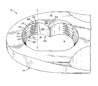
[0031] As shown in Fig. 1, bone plate 10 includes upper surface 12, lower
surface 14,
and apertures 16, 18. Thickness 20, shown in Figs. 4 and 5, of bone plate 10
is measured
between upper surface 12 and lower surface 14. Aperture 16 is defined by
interior wall 24.
Interior wall 24 include threaded portion 26, non-threaded portion 28,
transition portion 30, and
chamfer 32. As depicted herein, apertures 16, 18 are substantially identical
and aperture 18
includes the identical features of aperture 16. Therefore, for clarity, the
features of apertures 16,
18 are discussed herein only with reference to aperture 16. Additionally,
aperture 18 of the
4
BDDBOI 4522976v1
CA 02601482 2007-09-12
present invention may be replaced by an aperture having differing
characteristics, including any
known bone plate aperture configuration.
[0032] Threads 34 of threaded portion 26 of aperture 16 extend along
interior wall 24
through thread height 36 (Fig. 4). Thread height 36 extends along at least a
portion of thickness
20 of bone plate 10. Non-threaded portion 28 is positioned adjacent threaded
portion 26. In one
exemplary embodiment, non-threaded portion 28 covers at least a portion of
thickness 20 of bone
plate 10 through thread height 36. In this embodiment, the thickness of non-
threaded portion 28
is substantially equal to thread height 36. Chamfer 32, shown in Figs. 4 and
5, is positioned
above threaded portion 26 and non-threaded portion 28 and extends to upper
surface 12 of bone
plate 10.
[0033] As shown in Figs. 1-2, for example, threads 34 of threaded portion
26 extend
along a portion of interior wall 24 of bone plate 10 until reaching transition
portion 30.
Following transition portion 30 from threaded portion 26 to non-threaded
portion 28, threads 34
gradually integrate into interior wall 24 until, at the beginning of non-
threaded portion 28, they
are fully integrated. Conversely, following transition portion 30 from non-
threaded portion 28 to
threaded portion 26, threads 34 gradually rise from interior wall 24 until
full threads 34 exist and
threaded portion 26 begins. Thus, transition portion 30 delineates the part of
interior wall 24
along which the transition from threaded portion 26 to non-threaded portion
28, and vice-versa,
OMITS.
[0034] Each of threads 34 have a minor diameter equal to twice the minor
radius RI,
shown in Figs. 1 and 4. Minor radius R1 of each of threads 34 is measured from
center axis C,
extending through the center of aperture 16, to crest 44 of one of threads 34.
Additionally, each
of threads 34 have a major diameter equal to twice the major radius R2. Major
radius R2 is
measured from center axis C to root 48 (Fig. 4) of one of threads 34.
[0035] As shown in Figs. 1-7, threaded portion 26 is conical and non-
threaded portion 28
is cylindrical. Non-threaded portion 28 has a diameter equal to the diameter
of a cylinder having
an exterior surface that would be coplanar with the portion of interior wall
24 forming non-
threaded portion 28. In this embodiment, as best seen in Fig. 2, non-threaded
portion 28
intersects threaded portion 26. Non-threaded portion 28 also has a minimum
diameter and a
maximum diameter. The minimum diameter of threaded portion 26 is equal to the
smallest
minor diameter of threads 34. In this embodiment, the minor diameter of the
one of threads 34
BDDB01 4522976v1
CA 02601482 2007-09-12
nearest to lower surface 14 of bone plate 10 defines the minimum diameter.
Similarly, the
maximum diameter of threaded portion 26 is equal to the largest major diameter
of threads 34.
In this embodiment, the major diameter of the one of threads 34 nearest to
upper surface 12 of
bone plate 10 defines the maximum diameter. Specifically, the diameter of non-
threaded portion
28 is equal to or greater than the minimum diameter of threaded portion 26 and
equal to or less
than the maximum diameter of threaded portion 26. In this embodiment, as shown
in Fig. 2, the
diameter of non-threaded portion 28 is substantially equal to the mean of the
minimum diameter
and the maximum diameter of threaded portion 26.
[0036] As shown in the embodiment of Fig. 4, the major diameter of
threaded portion 26
decreases as thread height 36 approaches lower surface 14 of bone plate 10. In
another
exemplary embodiment, the threaded portion remains conical, but tapers in the
opposite
direction. In this embodiment, the minimum diameter of the threaded portion 26
would be equal
to the minor diameter of the one of threads 34 nearest upper surface 12 of
bone plate 10.
Similarly, the maximum diameter of threaded portion 26 would be equal to the
major diameter of
the one of threads 34 nearest lower surface 14 of bone plate 10. In this
embodiment, the major
diameter of threaded portion 26 decreases as thread height 36 approaches upper
surface 12 of
bone plate 10.
[0037] As shown in Fig. 4, threads 34 extend into transition portion 30
of aperture 16.
Due to the relative positions of threaded portion 26 and non-threaded portion
28, discussed in
detail above, threads 34 extend further along transition portion 30 of
interior wall 24 as the minor
diameter of threads 34 nears the diameter of non-threaded portion 28. Threads
34 extend furthest
into transition portion 30 at point 54, where the minor diameter of one of
threads 34 and the
diameter of non-threaded portion 28 are approximately equal. As threads 34
approach upper
surface 12 of bone plate 10, threads 34 require a shorter distance to
integrate into transition
portion 30 than at point 54. Similarly, as threads 34 approach lower surface
14 of bone plate 10,
threads 34 require a shorter distance to integrate into transition portion 30
than at point 54. As
shown in Fig. 5, aperture 16 and non-threaded portion 28 terminate at wall 56.
[0038] As shown in Fig. 6, bone plate 10 is positioned between bone 58
and bone screw
60. Bone screw 60 includes shank 62 having external threads 64 thereon and
head 66 having
external threads 68 thereon. External threads 68 of head 66 are sized for
mating engagement
with threads 34 of threaded portion 26 of bone plate 10. Head 66 of bone screw
60 further
6
BDDBOI 4522976v1
CA 02601482 2007-09-12
includes an attachment mechanism (not shown), e.g., a hexagonal shaped cavity,
designed for
mating engagement with a corresponding drive tool. Additionally, head 66 of
bone screw 60 can
be centered along shank 62 and longitudinal axis 68 of bone screw 60. As
shown, head 66
includes gap 70 cut therein to provide bone screw 60 with a self-tapping head,
i.e., a head
capable of forming its own threads when advanced into an aperture. In this
embodiment, head
66 of bone screw 60 is formed of a material having a hardness greater than the
material forming
bone plate 10. This allows for head 66 of bone screw 60 to remove a portion of
the material
forming bone plate 10 as it is advanced into aperture 16, facilitating the
creation of threads
therein. Advantageously, the use of a self-tapping head provides a tighter fit
between non-
threaded portion 26 and head 66 of bone screw 60 since the threads cut by head
66 will be sized
to tightly mate with the specific orientation of threads 68 of head 66.
[0039]
As bone screw 60 is positioned with shank 62 extending partially through
aperture
16, tip 72 of shank 62 contacts bone 58. At this point, bone 58 provides
resistance to the
advancement of bone screw 60 into bone 58. As this resistance is overcome and
bone screw 60
is threaded into bone 58, threads 68 of head 66 will eventually begin engaging
threads 34 of
threaded portion 26 of bone plate 10. At substantially the same time, threads
68 of head 66 will
also begin tapping threads into a portion of non-threaded portion 28, as
threaded portion 26 and
non-threaded portion 28 are configured to cooperatively engage head 66 of bone
screw 60.
Advantageously, the resistance encountered by head 66 due to the interaction
of threads 68 with
non-threaded portion 28 provides the surgeon with tactile feedback indicating
that head 66 of
bone screw 60 has encountered bone plate 10. Additionally, the interaction of
bone screw 60
with non-threaded portion 28 may create a greater force on head 66 of bone
screw 60 than
threaded portion 26, due, in part, to the cylindrical shape of non-threaded
portion 28. Therefore,
bone screw 60 may toggle axially about a pivot point within head 66 toward
threaded portion 26.
The toggling of bone screw 60 may create compression, similar to that created
by utilizing non-
threaded apertures, as discussed above. This provides the benefit of a non-
threaded bone plate
aperture, i.e., compression, while still providing the benefits of a threaded
aperture, i.e., locking
the bone screw in place. Once bone screw 60 is positioned with the bottom of
head 66
substantially coplanar with lower surface 14 of bone plate 10, as shown in
Fig. 7, bone screw 60
is securely locked in aperture 16.
7
BDDBOI 4522976v1
CA 02601482 2007-09-12
[0040] In the exemplary embodiment of Figs. 1-7, head 66 will tap
threads into non-
threaded portion 28 along all parts of non-threaded portion 28 having a
diameter less then the
major diameter of threads 68 of head 66. When the diameter of non-threaded
portion 28 is
greater then the major diameter of threads 68, threads 68 will not engage non-
threaded portion 28
and, therefore, will not tap threads into non-threaded portion 28. As
discussed in detail above,
this transition occurs at point 54 and approximates the mean of the minor
diameter and the major
diameter of threaded portion 26.
[0041] Figs. 8-20 depict apertures according to additional embodiments
of the present
invention. These apertures include several features which are identical to
aperture 16 of the
exemplary embodiment depicted in Figs. 1-7, discussed in detail above, and
identical reference
numerals have been used to indicate identical or substantially identical
features therebetween. In
the same manner as aperture pair 16, 18 is discussed herein above, the
features of aperture pairs
102 and 104, 122 and 124, and 150 and 152 are discussed in detail herein only
with reference to
apertures 102, 124, and 152, respectively.
[0042] Referring to Figs. 8-11, bone plate 100 includes apertures 102,
104 according to
another exemplary embodiment. Aperture 102 includes threaded portion 26 and
non-threaded
portion 106. Similar to aperture 16 of Figs. 1-7, threaded portion 26 of
aperture 16 is conical and
non-threaded portion 106 is cylindrical. Additionally, as shown in Fig. 11,
non-threaded portion
26 of hole 102 terminates at wall 108. In contrast to aperture 16 of Figs. 1-7
and with reference
to Fig. 9 of the present embodiment, the diameter of non-threaded portion 108
of aperture 102 is
substantially equal to the minimum diameter of threaded portion 26. In this
exemplary
embodiment, the bottom view of bone plate 100, shown in Fig. 9, appears to
show aperture 102
as having an identical configuration at threaded portion 26 and at non-
threaded portion 106.
However, as stated above and shown in Figs. 8, 10, and 11, threaded portion 26
is conical.
[0043] Figs. 12-15 depict bone plate 120 having apertures 122, 124
according to another
exemplary embodiment of the present invention. In contrast to aperture 102 of
Figs. 8-11, both
threaded portion 126 and non-threaded portion 128 of aperture 124 are conical
and taper at a
substantially identical angle. Thus, the minor diameter of threads 130 of
threaded portion 126
are equal, for each respective one of threads 130, to the diameter of non-
threaded portion 128 at
a point adjacent each respective one of threads 130. Specifically, as shown in
Fig. 14, interior
wall 24 forming non-threaded portion 128 forms plane 132 at an angle
substantially similar to an
8
BDDB01 4522976v1
CA 02601482 2007-09-12
angle formed by crests 134 of threads 130. In another exemplary embodiment,
non-threaded
portion 128 may have a taper angle which is greater than or less than the
taper angle of threaded
portion 126. As shown in Fig. 15, non-threaded portion terminates at wall 136.
[0044] Fig. 16 depicts another exemplary embodiment of apertures 16, 18
of Fig. 2 as
apertures 150, 152. In this embodiment, interior wall 24 of aperture 152
includes first portion
154 and second portion 156. In this embodiment, interior wall 24 is completely
threaded. Thus,
both first portion 154 and second portion 156 are threaded. Similar to
aperture 16 of Fig. 2, first
portion 154 is conical and second portion 156 is cylindrical. However, in
another embodiment,
second portion 156 may be conical. As depicted herein, the minor diameter of
each of threads
160 of second portion 156 are substantially equal to the minor diameter of
each of the
corresponding threads 158 of first portion 154. In this exemplary embodiment,
as shown in Figs.
18 and 19, threads 158 of second portion 156 (Fig. 19) have a difference
between the minor
diameter and major diameter of each of threads 158, measured from crests 161
and roots 163,
respectively, that is substantially less than the difference between the minor
diameter and the
major diameter of each of threads 160 of first portion 154 (Fig. 18), measured
from crests 157
and roots 159, respectively. As a result, the use of a self-tapping screw
having threads sized
similarly to threads 158 of first portion 154 would result in the head of the
screw deepening
threads 160 in second portion 156, which would increase the major diameter of
threads 160 of
second portion 156.
[0045] Referring to Fig. 20, bone plate 170 includes aperture 172
according to another
exemplary embodiment. Aperture 172 is defined by sides 174, 176, 178, 180,
182, 184 which
form a hexagon. In this exemplary embodiment, only sides 176, 180, 184 are
threaded.
Additionally, each of sides 174, 176, 178, 180, 182, 184 is substantially
vertical between upper
surface 12 and lower surface 14. In this embodiment, screw 60, shown in Fig.
4, having head 66
with cutout 70 may be utilized. When screw 60 is utilized with aperture 172 of
bone plate 170,
head 66 will tap threads into sides 174, 178, 182. This will provide the same
benefits as
discussed above with reference to the embodiment of Figs. 1-7. In addition to
a hexagonal
shape, aperture 172 may be in the form of a triangle, square, octagon, or any
other shape
providing sufficient coverage to retain the head of a screw in the desired
position. In another
exemplary embodiment, sides interior wall 174, 176, 178, 180, 182, 184 are
tapered. In another
9
BDDBOI 4522976v1
CA 02601482 2013-12-18
exemplary embodiment, sides 176, 180, 184 are tapered and sides 174, 178, 182
are
substantially vertical between upper surface 12 and lower surface 14 of bone
plate 170.
[0046]
While this invention has been described as having a preferred design, the
present invention can be further modified within known or customary practice
in the art to
which this invention pertains, provided such modifications fall within the
limits of the
appended claims.