Language selection

Search

Patent 2601555 Summary

Third-party information liability

Some of the information on this Web page has been provided by external sources. The Government of Canada is not responsible for the accuracy, reliability or currency of the information supplied by external sources. Users wishing to rely upon this information should consult directly with the source of the information. Content provided by external sources is not subject to official languages, privacy and accessibility requirements.

Claims and Abstract availability

Any discrepancies in the text and image of the Claims and Abstract are due to differing posting times. Text of the Claims and Abstract are posted:

  • At the time the application is open to public inspection;
  • At the time of issue of the patent (grant).
(12) Patent: (11) CA 2601555
(54) English Title: DEVICE FOR ADJUSTING THE FLOW-RATE OF A FLUID, PARTICULARLY MEDICAL OXYGEN AND COMPRESSED GASES IN GENERAL
(54) French Title: DISPOSITIF POUR REGLER LE DEBIT D'UN FLUIDE, PARTICULIEREMENT L'OXYGENE THERAPEUTIQUE ET LES GAZ COMPRIMES EN GENERAL
Status: Deemed expired
Bibliographic Data
(51) International Patent Classification (IPC):
  • G05D 7/01 (2006.01)
  • A61M 16/20 (2006.01)
  • F16K 31/44 (2006.01)
  • F17C 7/00 (2006.01)
(72) Inventors :
  • NICOLINI, GIANCARLO (Italy)
(73) Owners :
  • PERGOLA S.R.L. (Italy)
(71) Applicants :
  • PERGOLA S.R.L. (Italy)
(74) Agent: SMART & BIGGAR LLP
(74) Associate agent:
(45) Issued: 2015-02-03
(22) Filed Date: 2007-09-12
(41) Open to Public Inspection: 2008-03-18
Examination requested: 2012-07-05
Availability of licence: N/A
(25) Language of filing: English

Patent Cooperation Treaty (PCT): No

(30) Application Priority Data:
Application No. Country/Territory Date
06425643.1 European Patent Office (EPO) 2006-09-18

Abstracts

English Abstract

A device for adjusting the flow-rate of a fluid, particularly medical oxygen and compressed gases in general, which comprises a valve body which defines an input duct for a low-pressure fluid which is connected to a rotary flow control element, which has an output port which can be arranged at the calibrated holes of a flow-rate adjustment disk; the calibrated holes are connected to an output duct; an actuation handwheel is also provided which is functionally associated with the rotary flow control element; the actuation handwheel comprises means for positioning the flow control element so that the output port is arranged at at least one of the calibrated holes.


French Abstract

Dispositif permettant de régler le débit dun fluide, particulièrement loxygène thérapeutique et les gaz comprimés en général. Linvention comprend un corps de vanne qui définit un conduit dentrée pour un fluide basse pression qui est raccordé à un élément de commande de débit rotatif doté dun orifice de sortie qui peut être disposé sur les trous calibrés dun disque de réglage du débit. De plus, les trous calibrés sont raccordés à un conduit de sortie; un volant dactivation est prévu et peut être associé de façon fonctionnelle à lélément de commande de débit rotatif; et le volant dactivation comprend des éléments qui permettent de positionner lélément de commande de débit de sorte que lorifice de sortie soit disposé sur au moins un des trous calibrés.

Claims

Note: Claims are shown in the official language in which they were submitted.

6
THE EMBODIMENTS OF THE INVENTION IN WHICH AN EXCLUSIVE
PROPERTY OR PRIVILEGES IS CLAIMED ARE DEFINED AS FOLLOWS:
1. A device for
adjusting the flow-rate of a fluid, comprising a valve
body which defines an input duct for a low-pressure fluid which is connected
to
a rotary flow control element, which defines an output port which can be
arranged at the calibrated holes of a flow-rate adjustment disk, said
calibrated
holes being connected to at least one output duct, an actuation handwheel
being
further provided which is functionally associated with said rotary flow
control
element, comprising, in said actuation handwheel, means for stably positioning

said flow control element so that said output port is arranged at at least one
of
said calibrated holes, said actuation handwheel comprising a fixed lower
portion and a rotary upper movable portion which can move axially with
respect to said fixed lower portion, and said stable positioning means
comprise
a fixed front set of teeth which is defined by said fixed lower portion which
can
be coupled detachably to a movable front set of teeth formed in said upper
portion.
2. The device according to claim 1, wherein said adjustment disk is
arranged in a fixed position.
3. The device according to claim 1, wherein said adjustment disk has a
thickness which is substantially lower than one tenth of a millimeter.
4. The device according to claim 1, further comprising a perimetric
spacer which can be clamped by means of a cap which is associated with an
upper portion of said valve body.
5. The device according to claim 4, further comprising a shaft which is
rotatably associated with said valve body and is kept in position by a flange
which can engage said cap, said shaft having a polygonal portion for
monolithic
rotary engagement with said actuation handwheel.
6. The device according to claim 1, wherein said fixed lower portion has
a male set of teeth, which can engage a corresponding female set of teeth
which

7
is provided in said cap in order to define a preset circumferential position.
7. The device according to claim 1, wherein said fixed lower portion has
an outer border provided with a viewport for viewing an indicator arranged on
a
lateral surface of said movable upper portion.
8. The device according to claim 1, wherein said movable upper portion
has a connecting portion which defines a movable window for viewing a fixed
indicator formed by said fixed lower portion.
9. The device according to claim 1, wherein said movable upper portion
is kept in position by means of a ring which engages said shaft and acts on a
pusher spring in order to push said movable upper portion against said fixed
lower portion.

Description

Note: Descriptions are shown in the official language in which they were submitted.


CA 02601555 2013-10-15
1
The present invention relates to a device for adjusting the flow-rate of a
fluid,
particularly medical oxygen and compressed gases in general.
As is known, in order to dispense different gases and particularly medical
oxygen it is necessary to provide a device which allows to adjust the flow-
rate of the
fluid that is dispensed.
The solutions of the background art generally provide rotating disks which are

polygonally coupled to a rotating rod, connected to a handwheel which allows
to turn
the disk so as to place at least one of the provided calibrated holes at a
product
delivery port.
Such known solutions suffer problems of deformation and crushing of the disk
during rotation; moreover, with known solutions the rotating disk may arrange
itself
so that no holes are located at the output port and therefore the output flow
may even
be interrupted, with the consequent severe problems, in view also of the fact
that the
user might be a patient who is alone and is suffering a respiratory crisis.
As disclosed, a device for adjusting the flow-rate of a fluid, particularly
medical oxygen, allows to provide extremely precise calibrated holes without
running
the risk of damaging the disk in which the holes are provided.
Conveniently, a device in which there is a transit flow of gas, preventing the

risk of accidental interruptions of the oxygen flow is disclosed.
Object of the present invention is to provide a device which thanks to its
particular constructive characteristics is capable of giving the greatest
assurances of
reliability and safety in use.
Conveniently, a device as disclosed can be obtained easily from commonly
commercially available elements and materials and is further competitive from
a
merely economical standpoint.

CA 02601555 2013-10-15
2
This aim and these and other objects which will become better apparent
hereinafter are achieved by a device for adjusting the flow-rate of a fluid,
comprising
a valve body which defines an input duct for a low-pressure fluid which is
connected
to a rotary flow control element, which defines an output port which can be
arranged
at the calibrated holes of a flow-rate adjustment disk, said calibrated holes
being
connected to at least one output duct, an actuation handwheel being further
provided
which is functionally associated with said rotary flow control element,
comprising, in
said actuation handwheel, means for stably positioning said flow control
element so
that said output port is arranged at at least one of said calibrated holes,
said actuation
handwheel comprising a fixed lower portion and a rotary upper movable portion
which can move axially with respect to said fixed lower portion, and said
stable
positioning means comprise a fixed front set of teeth which is defined by said
fixed
lower portion which can be coupled detachably to a movable front set of teeth
formed
in said upper portion.
Further characteristics and advantages will become better apparent from the
description of a preferred but not exclusive embodiment of a device for
adjusting the
flow-rate of a fluid, particularly medical oxygen, illustrated by way of non-
limiting
example in the accompanying drawings, wherein:
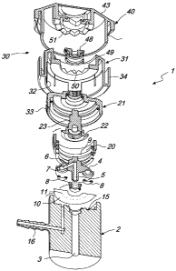
Figure 1 is a schematic perspective view of the flow-rate adjustment device
according to the invention;
Figure 2 is an exploded sectional perspective view of the device;
Figure 3 is a sectional view of the device, taken along a diametrical plane;
Figure 4 is a plan view of the flow-rate adjustment disk.
With reference to the figures, the device for adjusting the flow-rate of a
fluid,
particularly medical oxygen, generally designated by the reference numeral 1,
comprises a valve body 2, which defines an input duct 3 which is connected to
a
device for delivering a low-pressure fluid, generally oxygen.

CA 02601555 2007-09-12
3
At the end of the input duct 3 there is a rotary flow control element 4,
which defines an axial duct 5 on the continuation of the duct 3, which is
connected to a branch duct 6 which ends with an output port 7 where a
sealing 0-ring 8 is arranged.
The output port can be arranged at the surface of a flow-rate
adjustment disk, designated by the reference numeral 10, which has a low
thickness, lower than one tenth of a millimeter, and is provided
circumferentially with a uniformly distributed plurality of calibrated holes
11.
Other 0-rings, in addition to the 0-ring 8, can be provided on the
rotating body, on which a compression spring 9 acts, and merely have a
balancing function.
The disk 10, which is fixed, is applied at an upper abutment surface
of the valve body 2 and has a low thickness, substantially one tenth of a
millimeter, so that it is possible to provide extremely precise calibrated
holes by means of a laser beam.
The calibrated holes 11 are arranged at a connecting duct 15, which is
arranged so as to correspond to the extension of the calibrated holes and is
connected to an output duct 16 for dispensing the gas whose flow-rate is to
be adjusted; of course, nothing changes if the direction of flow is reversed.
The disk 10 is kept in position by means of a perimetric spacer 20,
which is clamped by means of a cap 21 arranged at the upper portion of the
valve body.
The cap 21 engages a flange 22 of a shaft 23 which is provided with a
polygonal portion 24 for rigid rotational engagement with an actuation
handwheel, generally designated by the reference numeral 30.
The actuation handwheel has the particularity that it is constituted by
a fixed lower portion 31, which is provided with a male set of teeth 32
which engages a corresponding female set of teeth 33 provided by the cap
21 so as to define a preset axial arrangement.

CA 02601555 2007-09-12
4
The lower portion 31 defines an outer border 34, which is provided
with a viewport 35, through which it is possible to view an indicator
arranged on the lateral surface of the movable upper portion 40 of the
handwheel, which has a side wall 41 which is arranged circumferentially
below the outer border 34 and has indications 42 which can be viewed from
the viewport 35.
The upper portion 40 further has a frustum-shaped connecting portion
43, which is provided with a movable window 44 for viewing a fixed
indicator 45 provided on the fixed portion 31, thus allowing to have an
indication of the flow-rate which is visible both at the lateral surface and
at
the upper surface.
The knob 30 is kept in position by means of a ring 48, which engages
the shaft 23 and acts on a pusher spring 49 which pushes the movable
portion 40 against the fixed lower portion 31 of the actuation handwheel.
The peculiar characteristic consists in that means for stably
positioning the flow control element are provided in the actuation
handwheel so as to position the output port 7 always at at least one of the
calibrated holes 11.
Such means are constituted by a fixed front set of teeth 50 provided
on the lower portion 31 and by a movable front set of teeth 51 provided on
the portion 40, which provide a precise mating, preventing the movable
upper portion, which is connected to the flow control element 4, from being
able to stop in a position in which the port 7 is not arranged at a hole 11.
The movable upper portion can rotate and perform an axial
translational motion in contrast with the action of the pusher spring 49 with
respect to the fixed portion, thus allowing to achieve easy and safe
adjustment together with the possibility of maximum safety, which prevents
unstable arrangements in which interruptions of flow would occur.
The calibrated holes lie substantially along the entire circumference
and there is a portion in which the flow is interrupted, said region being

CA 02601555 2007-09-12
From what has been described above it is therefore evident that the
invention achieves the proposed aim and objects, and in particular the fact is

stressed that the particular structure used, which allows to use a disk with
calibrated holes and fixed positioning, allows to achieve maximum
5 machining precision without subjecting such disk to stresses which might
damage it.
Moreover, the particular means used prevent the arrangement of the
flow control element in positions which prevent the dispensing of the flow,
except for the region preset for the initial portion with zero flow-rate.
The invention thus conceived is susceptible of numerous
modifications and variations, all of which are within the scope of the
inventive concept.
All the details may further be replaced with other technically
equivalent elements.
In practice, the materials used, as well as the contingent shapes and
dimensions, may be any according to requirements.

Representative Drawing
A single figure which represents the drawing illustrating the invention.
Administrative Status

For a clearer understanding of the status of the application/patent presented on this page, the site Disclaimer , as well as the definitions for Patent , Administrative Status , Maintenance Fee  and Payment History  should be consulted.

Administrative Status

Title Date
Forecasted Issue Date 2015-02-03
(22) Filed 2007-09-12
(41) Open to Public Inspection 2008-03-18
Examination Requested 2012-07-05
(45) Issued 2015-02-03
Deemed Expired 2019-09-12

Abandonment History

There is no abandonment history.

Payment History

Fee Type Anniversary Year Due Date Amount Paid Paid Date
Application Fee $400.00 2007-09-12
Maintenance Fee - Application - New Act 2 2009-09-14 $100.00 2009-08-06
Maintenance Fee - Application - New Act 3 2010-09-13 $100.00 2010-09-08
Maintenance Fee - Application - New Act 4 2011-09-12 $100.00 2011-08-11
Request for Examination $800.00 2012-07-05
Maintenance Fee - Application - New Act 5 2012-09-12 $200.00 2012-09-05
Maintenance Fee - Application - New Act 6 2013-09-12 $200.00 2013-09-04
Maintenance Fee - Application - New Act 7 2014-09-12 $200.00 2014-08-13
Final Fee $300.00 2014-11-24
Maintenance Fee - Patent - New Act 8 2015-09-14 $200.00 2015-08-10
Maintenance Fee - Patent - New Act 9 2016-09-12 $200.00 2016-08-25
Maintenance Fee - Patent - New Act 10 2017-09-12 $250.00 2017-09-04
Owners on Record

Note: Records showing the ownership history in alphabetical order.

Current Owners on Record
PERGOLA S.R.L.
Past Owners on Record
NICOLINI, GIANCARLO
Past Owners that do not appear in the "Owners on Record" listing will appear in other documentation within the application.
Documents

To view selected files, please enter reCAPTCHA code :


To view images, click a link in the Document Description column. To download the documents, select one or more checkboxes in the first column and then click the "Download Selected in PDF format (Zip Archive)" or the "Download Selected as Single PDF" button.

List of published and non-published patent-specific documents on the CPD .

If you have any difficulty accessing content, you can call the Client Service Centre at 1-866-997-1936 or send them an e-mail at CIPO Client Service Centre.


Document
Description 
Date
(yyyy-mm-dd) 
Number of pages   Size of Image (KB) 
Abstract 2007-09-12 1 23
Description 2007-09-12 5 227
Claims 2007-09-12 2 78
Drawings 2007-09-12 3 101
Representative Drawing 2008-02-19 1 16
Cover Page 2008-02-25 2 51
Description 2013-10-15 5 214
Claims 2013-10-15 2 65
Cover Page 2015-01-13 2 51
Assignment 2007-09-12 3 86
Prosecution-Amendment 2013-04-12 3 97
Prosecution-Amendment 2012-07-05 2 83
Fees 2013-09-04 2 83
Prosecution-Amendment 2013-10-15 7 300
Fees 2014-08-13 2 78
Correspondence 2014-11-24 2 73