Language selection

Search

Patent 2601846 Summary

Third-party information liability

Some of the information on this Web page has been provided by external sources. The Government of Canada is not responsible for the accuracy, reliability or currency of the information supplied by external sources. Users wishing to rely upon this information should consult directly with the source of the information. Content provided by external sources is not subject to official languages, privacy and accessibility requirements.

Claims and Abstract availability

Any discrepancies in the text and image of the Claims and Abstract are due to differing posting times. Text of the Claims and Abstract are posted:

  • At the time the application is open to public inspection;
  • At the time of issue of the patent (grant).
(12) Patent Application: (11) CA 2601846
(54) English Title: BROADBAND LAND MOBILE ANTENNA
(54) French Title: ANTENNE MOBILE TERRESTRE A LARGE BANDE
Status: Deemed Abandoned and Beyond the Period of Reinstatement - Pending Response to Notice of Disregarded Communication
Bibliographic Data
(51) International Patent Classification (IPC):
  • H04B 01/02 (2006.01)
(72) Inventors :
  • BABITSKY, GENNADY (Israel)
  • MARTISKAINEN, MATTI (Israel)
(73) Owners :
  • GALTRONICS LTD.
(71) Applicants :
  • GALTRONICS LTD. (Israel)
(74) Agent: SMART & BIGGAR LP
(74) Associate agent:
(45) Issued:
(86) PCT Filing Date: 2006-03-13
(87) Open to Public Inspection: 2006-09-21
Examination requested: 2010-02-19
Availability of licence: N/A
Dedicated to the Public: N/A
(25) Language of filing: English

Patent Cooperation Treaty (PCT): Yes
(86) PCT Filing Number: PCT/IL2006/000324
(87) International Publication Number: IL2006000324
(85) National Entry: 2007-09-12

(30) Application Priority Data:
Application No. Country/Territory Date
60/661,795 (United States of America) 2005-03-14

Abstracts

English Abstract


There is provided a monopole antenna including a helical radiating element
including a first longitudinal portion having a first winding pitch and a
second longitudinal portion having a second winding pitch and a cylindrical
radiating element generally coaxial with the helical radiating element and
extending along at least most of the first longitudinal portion.


French Abstract

L'invention concerne une antenne monopole comprenant un élément de rayonnement hélicoïdal doté d'une première partie longitudinale possédant un premier pas d'enroulement et une seconde partie longitudinale possédant un second pas d'enroulement et un élément de rayonnement cylindrique généralement coaxial par rapport à l'élément de rayonnement hélicoïdal et s'étendant le long d'au moins la majeure partie de la première partie longitudinale.

Claims

Note: Claims are shown in the official language in which they were submitted.

CLAIMS
1. A monopole antenna comprising:
a helical radiating element including a first longitudinal portion having a
first winding pitch and a second longitudinal portion having a second winding
pitch;
and
a cylindrical radiating element generally coaxial with said helical
radiating element and extending along at least most of said first longitudinal
portion.
2. A monopole antenna according to claim 1 and also comprising a
dielectric separator located between said helical radiating element and said
cylindrical
radiating element.
3. A monopole antenna according to claim 1 or claim 2 and also comprising
a dielectric insert located interior of said helical radiating element and
being configured
to maintain said first winding pitch of said first longitudinal portion of
said helical
radiating element.
4. A monopole antenna according to any of the previous claims wherein
said second winding pitch is greater than said first winding pitch.
5. A monopole antenna according to claim 4 and wherein said second
winding pitch is 40-50% greater than said first winding pitch.
6

Description

Note: Descriptions are shown in the official language in which they were submitted.


CA 02601846 2007-09-12
WO 2006/097919 PCT/IL2006/000324
BROADBAND LAND MOBILE ANTENNA
REFERENCE TO RELATED APPLICATIONS
The present application is related to U.S. Provisional Patent Application
Serial No. 60/661,795 filed March 14, 2005, and entitled BROADBAND LAND
MOBILE ANTENNA, the disclosure of whi.ch is hereby incorporated by reference
and
priority of which is hereby claimed pursuant to 37 CFR 1.78(a) (4) and (5)(i).
FIELD OF THE INVENTION
The present invention relates to antennas generally and more particularly
to broadband antennas for mobile devices.
BACKGROUND OF THE INVENTION
The following Patent documents are believed to represent the current
state of the art:
U.S. Patent: 4,772,895.
SUMMARY OF THE INVENTION
The present invention seeks to provide an improved antenna for mobile
devices.
There is thus provided in accordance with a preferred embodiment of the
present invention a monopole antenna including a helical radiating element
including a
first longitudinal portion having a first winding pitch and a second
longitudinal portion
having a second winding pitch and a cylindrical radiating element generally
coaxial
with the helical radiating element and extending along at least most of the
first
longitudinal portion.
In accordance with a preferred embodiment of the present invention the
monopole antenna also includes a dielectric separator located between the
helical

CA 02601846 2007-09-12
WO 2006/097919 PCT/IL2006/000324
radiating element and the cylindrical radiating element. Preferably, the
monopole
antenna also includes a dielectric insert located interior of the helical
radiating element
and being configured to maintain the first winding pitch of the first
longitudinal portion
of the helical radiating element.
In accordance with another preferred embodiment of the present
invention the second winding pitch is greater than the first winding pitch.
Preferably,
the second winding pitch is 40-50% greater than the first winding pitch.
BRIEF DESCRIPTION OF THE DRAWINGS
The present invention will be understood and appreciated more fully
from the following detailed description, taken in conjunction with the
drawings in
which:
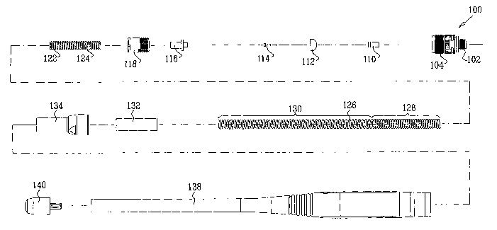
Fig. 1 is a simplified exploded view illustration of an antenna
constructed and operative in accordance with a preferred embodiment of the
present
invention;
Figs. 2A, 2B and 2C are, respectively, a simplified assembled pictorial
illustration, a partially cut away pictorial illustration and a sectional
illustration of the
antenna of Fig. 1, the sectional illustration being taken along section lines
IIC-IIC in
Fig. 2A;
Figs. 3A and 3B are a simplified assembled pictorial illustration and a
sectional illustration of a coil base internal support and a coil base
element, forming part
of the antenna assembly of Figs. 1- 2C, the sectional illustration being taken
along
section lines IIIB-IIIB in Fig. 3A;
Figs. 4A and 4B are a simplified assembled pictorial illustration and a
sectional illustration of the engagement of an antenna coil with the coil base
internal
support and the coil base element, as well as the mutual engagement therewith
of a pin
socket element, a pin socket collar and a pin, all forming part of the antenna
assembly of
Figs. I- 2C, the sectional illustration being taken along section lines IVB-
IVB in Fig.
4A;
Figs. 5A and 5B are a simplified assembled pictorial illustration and a
sectional illustration of the engagement of an antenna coil with the coil base
internal
2

CA 02601846 2007-09-12
WO 2006/097919 PCT/IL2006/000324
support and the coil base element, as well as the mutual engagement therewith
of pin
socket element, pin socket collar, pin and a base, all forming part of the
antenna
assembly of Figs. 1 - 2C, the sectional illustration being taken along section
lines
VB-VB in Fig. 5A; and
Figs. 6A and 6B are a sirnplifi.ed assembled pictorial illustration and a
sectional illustration of the engagement of the antenna coil with a dielectric
separator
and an antenna base element, as well as with the coil base internal support
and the coil
base element, and the mutual engagement therewith of pin socket element, pin
socket
collar, pin and base, all fonning part of the antenna assembly of Figs. 1 -
2C, the
sectional illustration being taken along section lines VIB-VIB in Fig. 6A.
3

CA 02601846 2007-09-12
WO 2006/097919 PCT/1L2006/000324
DETAILED DESCRIPTION OF PREFERRED EMBODIMENTS
Reference is now made to Fig. 1, which is a simplified exploded view
illustration of an antenna constructed and operative in accordance with a
preferred
embodiment of the present invention and to Figs. 2A, 2B and 2C, which are,
respectively, a simplified assembled pictorial illustration, a partially cut
away pictorial
illustration and a sectional illustration of the antenna of Fig. 1.
As seen in Figs. 1 and 2A - 2C, the antenna comprises a conductive base
100 having a relatively narrow externally threaded portion 102 which is
adapted to
threadably engage an antenna base socket in a communicator, such as a mobile
telephone. Base 100 also includes a relatively wide externally threaded
portion 104.
An insulative pin socket element 110 and an insulative pin socket collar
112 are disposed interiorly of base 100. A conductive pin 114 is also disposed
within
base 100, interiorly of pin socket element 110 and pin socket collar 112. A
conductive
coil base element 116 is seated in pin socket collar 112 and surrounds a head
portion of
pin 114. An insulative externally threaded locking element 118 threadably
engages
internal threading 120 formed on base 100.
In accordance with a preferred embodiment of the present invention, a
dielectric insert, such as an insulative coil base internal support 122, is
formed with a
coil pitch determining template 124 on an outer generally cylindrical surface
thereof,
which defmes a first coil pitch, preferably in the range of 7 - 8 turns per
cm.
Engagement of a helical radiating element, such as a conductive antenna coil
126, with
dielectric coil base internal support 122 ensures that a first longitudinal
portion,
designated by reference numeral 128, of the antenna coil 126 in engagement
with
template 124 has the first coil pitch. Preferably, a second longitudinal
portion,
designated by reference numeral 130, of antenna coil 126, which does not
engage
template 124, has a second coil pitch, typically 40-50% greater than the first
coil pitch,
preferably in the range of 4 - 6 turns per cm. The coil base element 116 and
the coil
base internal support 122 are shown in detail in Figs. 3A and 3B.
Figs. 4A and 4B illustrate the engagement of antenna coil 126 with the
coil base internal support 122 and the coil base element 116, as well as the
mutual
4

CA 02601846 2007-09-12
WO 2006/097919 PCT/IL2006/000324
engagement therewith of pin socket element 110, pin socket collar 112 and pin
114, all
forming part of the antenna assembly of Figs. 1 - 2C. It is appreciated that a
conductive
path is defined by tight engagement between the interior of coil 126 at the
bottom
thereof with an exterior surface 131 of coil base element 116 and by mutual
tight
engagement between coil base element 116 and pin 114.
Figs. 5A and 5B are similar to Figs. 4A and 4B and additionally illustrate
engagement of the pin socket element I 10 and pin socket collar 112 with base
100. It is
appreciated that a conductive path is defmed by tight engagement between the
interior
of coil 126 at the bottom thereof with an exterior surface 131 of coil base
element 116
and by mutual tight engagement between coil base element 11 6and pin 114,
which are
insulated from base 100 by pin socket collar 112 and pin socket element 110.
Figs. 6A and 6B are similar to Figs. 5A and 5B, and additionally
illustrate threadable engagement between internal threading 120 of base 100
and
externally threaded locking element 118, thereby locking the coil base element
116
within base 100. A dielectric separator 132 is disposed in engagement with
threaded
locking element 118 overlying an outside surface of first longitudinal portion
128 of
antenna coil 126 and separating first longitudinal portion 128 from a
cylindrical
radiating element, such as a conductive outer antenna base element 134,
mounted on
dielectric separator 132, which is shown with particular clarity in Fig. 2C.
The
conductive outer antenna base element 134 includes an interior threaded
portion 136
which threadably engages external threading 104 of base 100, as shown with
particular
clarity in Fig. 2C.
As seen with particular clarity in Fig. 2A, a dielectric flexible antenna
cover element 138 is located externally of the assembly that is described
hereinabove
with reference to Figs. 5A and 5B, and has an associated tip 140.
It is appreciated by persons skilled in the art that the present invention is
not limited by what has been particularly shown and described hereinabove.
Rather the
scope of the present invention includes both combinations and subcombinations
of
various features described hereinabove as well as variations and modifications
thereto
which would occur to a person of skill in the art upon reading the above
description and
which are not in the prior art.

Representative Drawing
A single figure which represents the drawing illustrating the invention.
Administrative Status

2024-08-01:As part of the Next Generation Patents (NGP) transition, the Canadian Patents Database (CPD) now contains a more detailed Event History, which replicates the Event Log of our new back-office solution.

Please note that "Inactive:" events refers to events no longer in use in our new back-office solution.

For a clearer understanding of the status of the application/patent presented on this page, the site Disclaimer , as well as the definitions for Patent , Event History , Maintenance Fee  and Payment History  should be consulted.

Event History

Description Date
Application Not Reinstated by Deadline 2012-03-13
Time Limit for Reversal Expired 2012-03-13
Deemed Abandoned - Failure to Respond to Maintenance Fee Notice 2011-03-14
Letter Sent 2010-03-16
Request for Examination Received 2010-02-19
All Requirements for Examination Determined Compliant 2010-02-19
Request for Examination Requirements Determined Compliant 2010-02-19
Inactive: Cover page published 2007-11-29
Inactive: Notice - National entry - No RFE 2007-11-27
Inactive: Declaration of entitlement - Formalities 2007-10-30
Inactive: First IPC assigned 2007-10-20
Application Received - PCT 2007-10-19
National Entry Requirements Determined Compliant 2007-09-12
Application Published (Open to Public Inspection) 2006-09-21

Abandonment History

Abandonment Date Reason Reinstatement Date
2011-03-14

Maintenance Fee

The last payment was received on 2010-03-15

Note : If the full payment has not been received on or before the date indicated, a further fee may be required which may be one of the following

  • the reinstatement fee;
  • the late payment fee; or
  • additional fee to reverse deemed expiry.

Patent fees are adjusted on the 1st of January every year. The amounts above are the current amounts if received by December 31 of the current year.
Please refer to the CIPO Patent Fees web page to see all current fee amounts.

Fee History

Fee Type Anniversary Year Due Date Paid Date
Basic national fee - standard 2007-09-12
MF (application, 2nd anniv.) - standard 02 2008-03-13 2008-01-10
MF (application, 3rd anniv.) - standard 03 2009-03-13 2009-03-05
Request for examination - standard 2010-02-19
MF (application, 4th anniv.) - standard 04 2010-03-15 2010-03-15
Owners on Record

Note: Records showing the ownership history in alphabetical order.

Current Owners on Record
GALTRONICS LTD.
Past Owners on Record
GENNADY BABITSKY
MATTI MARTISKAINEN
Past Owners that do not appear in the "Owners on Record" listing will appear in other documentation within the application.
Documents

To view selected files, please enter reCAPTCHA code :


To view images, click a link in the Document Description column. To download the documents, select one or more checkboxes in the first column and then click the "Download Selected in PDF format (Zip Archive)" or the "Download Selected as Single PDF" button.

List of published and non-published patent-specific documents on the CPD .

If you have any difficulty accessing content, you can call the Client Service Centre at 1-866-997-1936 or send them an e-mail at CIPO Client Service Centre.


Document
Description 
Date
(yyyy-mm-dd) 
Number of pages   Size of Image (KB) 
Description 2007-09-11 5 241
Representative drawing 2007-09-11 1 14
Drawings 2007-09-11 7 173
Abstract 2007-09-11 1 59
Claims 2007-09-11 1 30
Reminder of maintenance fee due 2007-11-26 1 113
Notice of National Entry 2007-11-26 1 195
Acknowledgement of Request for Examination 2010-03-15 1 177
Courtesy - Abandonment Letter (Maintenance Fee) 2011-05-08 1 173
Correspondence 2007-10-29 2 58
Fees 2009-03-04 1 36
Fees 2010-03-14 1 35