Sélection de la langue

Search

Sommaire du brevet 2601846 

Énoncé de désistement de responsabilité concernant l'information provenant de tiers

Une partie des informations de ce site Web a été fournie par des sources externes. Le gouvernement du Canada n'assume aucune responsabilité concernant la précision, l'actualité ou la fiabilité des informations fournies par les sources externes. Les utilisateurs qui désirent employer cette information devraient consulter directement la source des informations. Le contenu fourni par les sources externes n'est pas assujetti aux exigences sur les langues officielles, la protection des renseignements personnels et l'accessibilité.

Disponibilité de l'Abrégé et des Revendications

L'apparition de différences dans le texte et l'image des Revendications et de l'Abrégé dépend du moment auquel le document est publié. Les textes des Revendications et de l'Abrégé sont affichés :

  • lorsque la demande peut être examinée par le public;
  • lorsque le brevet est émis (délivrance).
(12) Demande de brevet: (11) CA 2601846
(54) Titre français: ANTENNE MOBILE TERRESTRE A LARGE BANDE
(54) Titre anglais: BROADBAND LAND MOBILE ANTENNA
Statut: Réputée abandonnée et au-delà du délai pour le rétablissement - en attente de la réponse à l’avis de communication rejetée
Données bibliographiques
(51) Classification internationale des brevets (CIB):
  • H04B 01/02 (2006.01)
(72) Inventeurs :
  • BABITSKY, GENNADY (Israël)
  • MARTISKAINEN, MATTI (Israël)
(73) Titulaires :
  • GALTRONICS LTD.
(71) Demandeurs :
  • GALTRONICS LTD. (Israël)
(74) Agent: SMART & BIGGAR LP
(74) Co-agent:
(45) Délivré:
(86) Date de dépôt PCT: 2006-03-13
(87) Mise à la disponibilité du public: 2006-09-21
Requête d'examen: 2010-02-19
Licence disponible: S.O.
Cédé au domaine public: S.O.
(25) Langue des documents déposés: Anglais

Traité de coopération en matière de brevets (PCT): Oui
(86) Numéro de la demande PCT: PCT/IL2006/000324
(87) Numéro de publication internationale PCT: IL2006000324
(85) Entrée nationale: 2007-09-12

(30) Données de priorité de la demande:
Numéro de la demande Pays / territoire Date
60/661,795 (Etats-Unis d'Amérique) 2005-03-14

Abrégés

Abrégé français

L'invention concerne une antenne monopole comprenant un élément de rayonnement hélicoïdal doté d'une première partie longitudinale possédant un premier pas d'enroulement et une seconde partie longitudinale possédant un second pas d'enroulement et un élément de rayonnement cylindrique généralement coaxial par rapport à l'élément de rayonnement hélicoïdal et s'étendant le long d'au moins la majeure partie de la première partie longitudinale.


Abrégé anglais


There is provided a monopole antenna including a helical radiating element
including a first longitudinal portion having a first winding pitch and a
second longitudinal portion having a second winding pitch and a cylindrical
radiating element generally coaxial with the helical radiating element and
extending along at least most of the first longitudinal portion.

Revendications

Note : Les revendications sont présentées dans la langue officielle dans laquelle elles ont été soumises.


CLAIMS
1. A monopole antenna comprising:
a helical radiating element including a first longitudinal portion having a
first winding pitch and a second longitudinal portion having a second winding
pitch;
and
a cylindrical radiating element generally coaxial with said helical
radiating element and extending along at least most of said first longitudinal
portion.
2. A monopole antenna according to claim 1 and also comprising a
dielectric separator located between said helical radiating element and said
cylindrical
radiating element.
3. A monopole antenna according to claim 1 or claim 2 and also comprising
a dielectric insert located interior of said helical radiating element and
being configured
to maintain said first winding pitch of said first longitudinal portion of
said helical
radiating element.
4. A monopole antenna according to any of the previous claims wherein
said second winding pitch is greater than said first winding pitch.
5. A monopole antenna according to claim 4 and wherein said second
winding pitch is 40-50% greater than said first winding pitch.
6

Description

Note : Les descriptions sont présentées dans la langue officielle dans laquelle elles ont été soumises.

CA 02601846 2007-09-12
WO 2006/097919 PCT/IL2006/000324
BROADBAND LAND MOBILE ANTENNA
REFERENCE TO RELATED APPLICATIONS
The present application is related to U.S. Provisional Patent Application
Serial No. 60/661,795 filed March 14, 2005, and entitled BROADBAND LAND
MOBILE ANTENNA, the disclosure of whi.ch is hereby incorporated by reference
and
priority of which is hereby claimed pursuant to 37 CFR 1.78(a) (4) and (5)(i).
FIELD OF THE INVENTION
The present invention relates to antennas generally and more particularly
to broadband antennas for mobile devices.
BACKGROUND OF THE INVENTION
The following Patent documents are believed to represent the current
state of the art:
U.S. Patent: 4,772,895.
SUMMARY OF THE INVENTION
The present invention seeks to provide an improved antenna for mobile
devices.
There is thus provided in accordance with a preferred embodiment of the
present invention a monopole antenna including a helical radiating element
including a
first longitudinal portion having a first winding pitch and a second
longitudinal portion
having a second winding pitch and a cylindrical radiating element generally
coaxial
with the helical radiating element and extending along at least most of the
first
longitudinal portion.
In accordance with a preferred embodiment of the present invention the
monopole antenna also includes a dielectric separator located between the
helical

CA 02601846 2007-09-12
WO 2006/097919 PCT/IL2006/000324
radiating element and the cylindrical radiating element. Preferably, the
monopole
antenna also includes a dielectric insert located interior of the helical
radiating element
and being configured to maintain the first winding pitch of the first
longitudinal portion
of the helical radiating element.
In accordance with another preferred embodiment of the present
invention the second winding pitch is greater than the first winding pitch.
Preferably,
the second winding pitch is 40-50% greater than the first winding pitch.
BRIEF DESCRIPTION OF THE DRAWINGS
The present invention will be understood and appreciated more fully
from the following detailed description, taken in conjunction with the
drawings in
which:
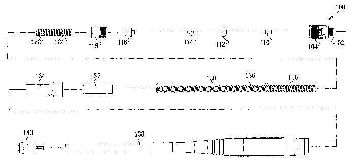
Fig. 1 is a simplified exploded view illustration of an antenna
constructed and operative in accordance with a preferred embodiment of the
present
invention;
Figs. 2A, 2B and 2C are, respectively, a simplified assembled pictorial
illustration, a partially cut away pictorial illustration and a sectional
illustration of the
antenna of Fig. 1, the sectional illustration being taken along section lines
IIC-IIC in
Fig. 2A;
Figs. 3A and 3B are a simplified assembled pictorial illustration and a
sectional illustration of a coil base internal support and a coil base
element, forming part
of the antenna assembly of Figs. 1- 2C, the sectional illustration being taken
along
section lines IIIB-IIIB in Fig. 3A;
Figs. 4A and 4B are a simplified assembled pictorial illustration and a
sectional illustration of the engagement of an antenna coil with the coil base
internal
support and the coil base element, as well as the mutual engagement therewith
of a pin
socket element, a pin socket collar and a pin, all forming part of the antenna
assembly of
Figs. I- 2C, the sectional illustration being taken along section lines IVB-
IVB in Fig.
4A;
Figs. 5A and 5B are a simplified assembled pictorial illustration and a
sectional illustration of the engagement of an antenna coil with the coil base
internal
2

CA 02601846 2007-09-12
WO 2006/097919 PCT/IL2006/000324
support and the coil base element, as well as the mutual engagement therewith
of pin
socket element, pin socket collar, pin and a base, all forming part of the
antenna
assembly of Figs. 1 - 2C, the sectional illustration being taken along section
lines
VB-VB in Fig. 5A; and
Figs. 6A and 6B are a sirnplifi.ed assembled pictorial illustration and a
sectional illustration of the engagement of the antenna coil with a dielectric
separator
and an antenna base element, as well as with the coil base internal support
and the coil
base element, and the mutual engagement therewith of pin socket element, pin
socket
collar, pin and base, all fonning part of the antenna assembly of Figs. 1 -
2C, the
sectional illustration being taken along section lines VIB-VIB in Fig. 6A.
3

CA 02601846 2007-09-12
WO 2006/097919 PCT/1L2006/000324
DETAILED DESCRIPTION OF PREFERRED EMBODIMENTS
Reference is now made to Fig. 1, which is a simplified exploded view
illustration of an antenna constructed and operative in accordance with a
preferred
embodiment of the present invention and to Figs. 2A, 2B and 2C, which are,
respectively, a simplified assembled pictorial illustration, a partially cut
away pictorial
illustration and a sectional illustration of the antenna of Fig. 1.
As seen in Figs. 1 and 2A - 2C, the antenna comprises a conductive base
100 having a relatively narrow externally threaded portion 102 which is
adapted to
threadably engage an antenna base socket in a communicator, such as a mobile
telephone. Base 100 also includes a relatively wide externally threaded
portion 104.
An insulative pin socket element 110 and an insulative pin socket collar
112 are disposed interiorly of base 100. A conductive pin 114 is also disposed
within
base 100, interiorly of pin socket element 110 and pin socket collar 112. A
conductive
coil base element 116 is seated in pin socket collar 112 and surrounds a head
portion of
pin 114. An insulative externally threaded locking element 118 threadably
engages
internal threading 120 formed on base 100.
In accordance with a preferred embodiment of the present invention, a
dielectric insert, such as an insulative coil base internal support 122, is
formed with a
coil pitch determining template 124 on an outer generally cylindrical surface
thereof,
which defmes a first coil pitch, preferably in the range of 7 - 8 turns per
cm.
Engagement of a helical radiating element, such as a conductive antenna coil
126, with
dielectric coil base internal support 122 ensures that a first longitudinal
portion,
designated by reference numeral 128, of the antenna coil 126 in engagement
with
template 124 has the first coil pitch. Preferably, a second longitudinal
portion,
designated by reference numeral 130, of antenna coil 126, which does not
engage
template 124, has a second coil pitch, typically 40-50% greater than the first
coil pitch,
preferably in the range of 4 - 6 turns per cm. The coil base element 116 and
the coil
base internal support 122 are shown in detail in Figs. 3A and 3B.
Figs. 4A and 4B illustrate the engagement of antenna coil 126 with the
coil base internal support 122 and the coil base element 116, as well as the
mutual
4

CA 02601846 2007-09-12
WO 2006/097919 PCT/IL2006/000324
engagement therewith of pin socket element 110, pin socket collar 112 and pin
114, all
forming part of the antenna assembly of Figs. 1 - 2C. It is appreciated that a
conductive
path is defined by tight engagement between the interior of coil 126 at the
bottom
thereof with an exterior surface 131 of coil base element 116 and by mutual
tight
engagement between coil base element 116 and pin 114.
Figs. 5A and 5B are similar to Figs. 4A and 4B and additionally illustrate
engagement of the pin socket element I 10 and pin socket collar 112 with base
100. It is
appreciated that a conductive path is defmed by tight engagement between the
interior
of coil 126 at the bottom thereof with an exterior surface 131 of coil base
element 116
and by mutual tight engagement between coil base element 11 6and pin 114,
which are
insulated from base 100 by pin socket collar 112 and pin socket element 110.
Figs. 6A and 6B are similar to Figs. 5A and 5B, and additionally
illustrate threadable engagement between internal threading 120 of base 100
and
externally threaded locking element 118, thereby locking the coil base element
116
within base 100. A dielectric separator 132 is disposed in engagement with
threaded
locking element 118 overlying an outside surface of first longitudinal portion
128 of
antenna coil 126 and separating first longitudinal portion 128 from a
cylindrical
radiating element, such as a conductive outer antenna base element 134,
mounted on
dielectric separator 132, which is shown with particular clarity in Fig. 2C.
The
conductive outer antenna base element 134 includes an interior threaded
portion 136
which threadably engages external threading 104 of base 100, as shown with
particular
clarity in Fig. 2C.
As seen with particular clarity in Fig. 2A, a dielectric flexible antenna
cover element 138 is located externally of the assembly that is described
hereinabove
with reference to Figs. 5A and 5B, and has an associated tip 140.
It is appreciated by persons skilled in the art that the present invention is
not limited by what has been particularly shown and described hereinabove.
Rather the
scope of the present invention includes both combinations and subcombinations
of
various features described hereinabove as well as variations and modifications
thereto
which would occur to a person of skill in the art upon reading the above
description and
which are not in the prior art.

Dessin représentatif
Une figure unique qui représente un dessin illustrant l'invention.
États administratifs

2024-08-01 : Dans le cadre de la transition vers les Brevets de nouvelle génération (BNG), la base de données sur les brevets canadiens (BDBC) contient désormais un Historique d'événement plus détaillé, qui reproduit le Journal des événements de notre nouvelle solution interne.

Veuillez noter que les événements débutant par « Inactive : » se réfèrent à des événements qui ne sont plus utilisés dans notre nouvelle solution interne.

Pour une meilleure compréhension de l'état de la demande ou brevet qui figure sur cette page, la rubrique Mise en garde , et les descriptions de Brevet , Historique d'événement , Taxes périodiques et Historique des paiements devraient être consultées.

Historique d'événement

Description Date
Demande non rétablie avant l'échéance 2012-03-13
Le délai pour l'annulation est expiré 2012-03-13
Réputée abandonnée - omission de répondre à un avis sur les taxes pour le maintien en état 2011-03-14
Lettre envoyée 2010-03-16
Requête d'examen reçue 2010-02-19
Toutes les exigences pour l'examen - jugée conforme 2010-02-19
Exigences pour une requête d'examen - jugée conforme 2010-02-19
Inactive : Page couverture publiée 2007-11-29
Inactive : Notice - Entrée phase nat. - Pas de RE 2007-11-27
Inactive : Déclaration des droits - Formalités 2007-10-30
Inactive : CIB en 1re position 2007-10-20
Demande reçue - PCT 2007-10-19
Exigences pour l'entrée dans la phase nationale - jugée conforme 2007-09-12
Demande publiée (accessible au public) 2006-09-21

Historique d'abandonnement

Date d'abandonnement Raison Date de rétablissement
2011-03-14

Taxes périodiques

Le dernier paiement a été reçu le 2010-03-15

Avis : Si le paiement en totalité n'a pas été reçu au plus tard à la date indiquée, une taxe supplémentaire peut être imposée, soit une des taxes suivantes :

  • taxe de rétablissement ;
  • taxe pour paiement en souffrance ; ou
  • taxe additionnelle pour le renversement d'une péremption réputée.

Les taxes sur les brevets sont ajustées au 1er janvier de chaque année. Les montants ci-dessus sont les montants actuels s'ils sont reçus au plus tard le 31 décembre de l'année en cours.
Veuillez vous référer à la page web des taxes sur les brevets de l'OPIC pour voir tous les montants actuels des taxes.

Historique des taxes

Type de taxes Anniversaire Échéance Date payée
Taxe nationale de base - générale 2007-09-12
TM (demande, 2e anniv.) - générale 02 2008-03-13 2008-01-10
TM (demande, 3e anniv.) - générale 03 2009-03-13 2009-03-05
Requête d'examen - générale 2010-02-19
TM (demande, 4e anniv.) - générale 04 2010-03-15 2010-03-15
Titulaires au dossier

Les titulaires actuels et antérieures au dossier sont affichés en ordre alphabétique.

Titulaires actuels au dossier
GALTRONICS LTD.
Titulaires antérieures au dossier
GENNADY BABITSKY
MATTI MARTISKAINEN
Les propriétaires antérieurs qui ne figurent pas dans la liste des « Propriétaires au dossier » apparaîtront dans d'autres documents au dossier.
Documents

Pour visionner les fichiers sélectionnés, entrer le code reCAPTCHA :


Pour visualiser une image, cliquer sur un lien dans la colonne description du document. Pour télécharger l'image (les images), cliquer l'une ou plusieurs cases à cocher dans la première colonne et ensuite cliquer sur le bouton "Télécharger sélection en format PDF (archive Zip)" ou le bouton "Télécharger sélection (en un fichier PDF fusionné)".

Liste des documents de brevet publiés et non publiés sur la BDBC .

Si vous avez des difficultés à accéder au contenu, veuillez communiquer avec le Centre de services à la clientèle au 1-866-997-1936, ou envoyer un courriel au Centre de service à la clientèle de l'OPIC.


Description du
Document 
Date
(aaaa-mm-jj) 
Nombre de pages   Taille de l'image (Ko) 
Description 2007-09-11 5 241
Dessin représentatif 2007-09-11 1 14
Dessins 2007-09-11 7 173
Abrégé 2007-09-11 1 59
Revendications 2007-09-11 1 30
Rappel de taxe de maintien due 2007-11-26 1 113
Avis d'entree dans la phase nationale 2007-11-26 1 195
Accusé de réception de la requête d'examen 2010-03-15 1 177
Courtoisie - Lettre d'abandon (taxe de maintien en état) 2011-05-08 1 173
Correspondance 2007-10-29 2 58
Taxes 2009-03-04 1 36
Taxes 2010-03-14 1 35