Language selection

Search

Patent 2601947 Summary

Third-party information liability

Some of the information on this Web page has been provided by external sources. The Government of Canada is not responsible for the accuracy, reliability or currency of the information supplied by external sources. Users wishing to rely upon this information should consult directly with the source of the information. Content provided by external sources is not subject to official languages, privacy and accessibility requirements.

Claims and Abstract availability

Any discrepancies in the text and image of the Claims and Abstract are due to differing posting times. Text of the Claims and Abstract are posted:

  • At the time the application is open to public inspection;
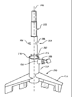
  • At the time of issue of the patent (grant).
(12) Patent: (11) CA 2601947
(54) English Title: MIXER, MIXING IMPLEMENT AND ASSOCIATED ATTACHMENT MECHANISM
(54) French Title: MELANGEUR, APPAREIL DE MELANGE ET MECANISME DE FIXATION ASSOCIE
Status: Granted and Issued
Bibliographic Data
(51) International Patent Classification (IPC):
  • F16D 1/108 (2006.01)
(72) Inventors :
  • SCHNIPKE, JANICE J. (United States of America)
  • BLACKBURN, NEAL H. (United States of America)
(73) Owners :
  • PREMARK FEG L.L.C.
(71) Applicants :
  • PREMARK FEG L.L.C. (United States of America)
(74) Agent: FINLAYSON & SINGLEHURST
(74) Associate agent:
(45) Issued: 2010-05-11
(86) PCT Filing Date: 2006-02-27
(87) Open to Public Inspection: 2006-08-31
Examination requested: 2007-08-20
Availability of licence: N/A
Dedicated to the Public: N/A
(25) Language of filing: English

Patent Cooperation Treaty (PCT): Yes
(86) PCT Filing Number: PCT/IB2006/050609
(87) International Publication Number: WO 2006090349
(85) National Entry: 2007-08-20

(30) Application Priority Data:
Application No. Country/Territory Date
11/068,178 (United States of America) 2005-02-28

Abstracts

English Abstract


A mixing implement includes a body having a mixing portion ( (214) and a
connecting portion (212) , the connecting portion having an upper shaft
receiving opening formed therein and a side opening (224) that leads to the
shaft receiving opening, the shaft receiving opening having a drive pin (202)
receiving recess (218) , the side opening and the drive pin receiving recess
located substantially diametrically opposite each other with the side opening
at a height corresponding to at least part of the drive pin receiving recess.
A retainer (50) is movably coupled with the connecting portion through the
side opening and biased into an inward position in which an inner portion of
the retainer is normally positioned within the shaft receiving opening, the
retainer movable to an outward position in which the inner portion of the
retainer is at least partially retracted from the shaft receiving opening.


French Abstract

Appareil de mélange composé d'un corps possédant une partie mélange (214) et une partie accouplement (212). Cette dernière présente une ouverture supérieure conçue pour recevoir une tige et une ouverture latérale (224) conduisant à ladite ouverture. Celle-ci comporte un évidement (218) conçu pour loger un goujon (202) et placé diamétralement opposé à l'ouverture latérale, celle-ci étant située à une hauteur correspondant à au moins une partie de l'évidement recevant le goujon. Un élément de retenue (50) est accouplé mobile à la partie d'accouplement à travers l'ouverture latérale et sollicité dans une position tournée vers l'intérieur dans laquelle une partie intérieure de cet élément est normalement placée à l'intérieur de l'ouverture recevant la tige, cet élément de retenue étant mobile vers une position tournée vers l'extérieur dans laquelle la partie intérieure dudit élément de retenue est au moins partiellement placée en retrait par rapport à l'ouverture de réception de tige.

Claims

Note: Claims are shown in the official language in which they were submitted.

5
Claims
[1] A mixer comprising:
a mixer body having a rotatable output shaft and a motor operatively coupled
to
the output shaft, the output shaft arranged to rotate around a shaft axis and
orbit
around another axis, the output shaft including a drive pin extending
sidewardly
therefrom and a retaining recess formed therein, the drive pin and the
retaining
recess on substantially diametrically opposed portions of the output shaft, a
distance from a lower end of the output shaft to the drive pin is
substantially the
same as a distance from the lower end of the output shaft to the retaining
recess;
a mixing implement having a connecting portion with a shaft receiving opening
having a drive pin receiving recess, a side opening located in the connecting
portion and leading to the shaft receiving opening, and a retainer coupled to
the
mixing implement for movement along the side opening between an inward
position in which at least part of said retainer is received in the retaining
recess
when the shaft is received in the shaft receiving opening to axially couple
the
mixing implement and the output shaft and a retracted position in which the
retainer retracts from the retaining recess to permit separation of the output
shaft
and the mixing implement.
[2] The mixer of claim 1 wherein the retainer comprises a spring-loaded
plunger
assembly with an external grip head.
[3] The mixer of claim 1 wherein the drive pin receiving recess includes side
chamfers for directing the drive pin into the drive pin receiving recess.
[4] The mixer of claim 1 wherein the drive pin receiving recess extends
through an
entire radial thickness of a wall of the connecting portion of the mixing
implement.
[5] The mixer of claim 1 wherein the retaining recess includes a substantially
flat
inward surface.
[6] The mixer of claim 1 wherein the retaining recess has a variable depth.
[7] A mixing implement for attachment to a mixer, the mixing implement
comprising:
a connecting portion and a mixing portion, the mixing portion extending
downward from the connecting portion, the connecting portion having an upper
shaft receiving opening formed therein and a side opening that leads to the
shaft
receiving opening, the shaft receiving opening having a single drive pin
receiving recess, the side opening and the drive pin receiving recess located
on
substantially diametrically opposite portions of the connecting portion with
the
side opening at a height corresponding to at least part of the drive pin
receiving

6
recess, the side opening spaced from a top of the connecting portion; and
a retaining pin movably coupled with the connecting portion through the side
opening, a spring positioned to bias the retaining pin into an inward position
in
which an inner end of the retaining pin is normally positioned within the
shaft
receiving opening, the retaining pin movable to an outward position in which
the
inner end of the retaining pin is at least partially retracted from the shaft
receiving opening, the retaining pin includes a gripping portion located
externally of the connecting portion for enabling manual retraction of the
retaining pin from the inward position to the outward position.
[8] The mixing implement of claim 7 wherein the drive pin receiving recess
includes
side chamfers for directing the drive pin into the drive pin receiving recess.
[9] The mixing implement of claim 7 wherein the drive pin receiving recess
extends
through an entire radial thickness of the connecting portion of the mixing
implement.
[10] A mixing implement for attachment to a mixer comprising:
a connecting portion and a mixing portion, the mixing portion extending
downward from the connecting portion, the connecting portion having an upper,
circumferential shaft receiving opening formed therein and a side opening that
leads to the circumferential shaft receiving opening, the circumferential
shaft
receiving opening having a drive pin receiving recess, the side opening and
the
drive pin receiving recess located on substantially diametrically opposite
portions
of the connecting portion with the side opening at a height corresponding to
at
least part of the drive pin receiving recess; and
a retainer movably coupled with the connecting portion through the side
opening
and biased into an inward position in which an inner portion of the retainer
is
normally positioned within the circumferential shaft receiving opening, the
retainer movable to an outward position in which the inner portion of the
retainer
is at least partially retracted from the circumferential shaft receiving
opening.
[11] The mixing implement of claim 10 wherein the drive pin receiving recess
includes side chamfers for directing the drive pin into the drive pin
receiving
recess.
[12] The mixing implement of claim 10 wherein the drive pin receiving recess
extends through an entire radial thickness of the connecting portion of the
mixing
implement.

Description

Note: Descriptions are shown in the official language in which they were submitted.


CA 02601947 2007-08-20
WO 2006/090349 PCT/IB2006/050609
1
Description
MIXER, MIXING IMPLEMENT AND ASSOCIATED
ATTACHMENT MECHANISM
TECHNICAL FIELD
[1] This application relates generally to an attachment mechanism or system
used with
a mixing machine and, more specifically, an attachment mechanism used for
connecting mixing implements to a rotatable output component of a mixing
machine.
BACKGROUND
[2] Mixers are used to mix and blend a variety of materials such as food
products. The
mixers typically include a removable mixing implement that is attachable to a
rotatable
and/or orbitable output shaft of the mixer. Mixing implements may come in
various
sizes and shapes and include agitators such as whips, dough hooks, beaters,
etc. The
mixing implements are typically removably coupled to the output shaft to
enable the
mixing implements to be removed or replaced for cleaning, repair, use of a
different
type of mixing implement, etc.
[3] One common type of attachment arrangement for mixing implements is a
bayonet
style connection. Alternative attachment arrangements are described in U.S.
Patent
Publication No. US 2002/0181322 Al. While the attachment arrangements in U.S.
Patent Publication No. US 2002/0181322 Al are useful, in some cases it may be
difficult to adapt such arrangements to smaller size mixers and smaller size
mixing
implements due to size and space limitations on smaller mixing implements
and/or
mixer shafts.
SUMMARY
[4] In one aspect, a mixing implement includes a body having a mixing portion
and a
connecting portion, the connecting portion having an upper shaft receiving
opening
formed therein and a side opening that leads to the shaft receiving opening,
the shaft
receiving opening having a drive pin receiving recess, the side opening and
the drive
pin receiving recess located substantially diametrically opposite each other
with the
side opening at a height corresponding to at least part of the drive pin
receiving recess.
A retainer is movably coupled with the connecting portion through the side
opening
and biased into an inward position in which an inner portion of the retainer
is normally
positioned within the shaft receiving opening, the retainer movable to an
outward
position in which the inner portion of the retainer is at least partially
retracted from the
shaft receiving opening.
BRIEF DESCRIPTION OF THE DRAWINGS
[5] Figs. 1-3 depict one embodiment of a mixing implement attachment system;

CA 02601947 2007-08-20
WO 2006/090349 PCT/IB2006/050609
2
[6] Fig 4 is an exploded, perspective cross sectional view of the actuator
assembly of
the embodiment of Figs. 1-3; and
[7] Fig. 5 shows an exemplary mixer construction.
DETAILED DESCRIPTION
[8] Referring now to Figs. 1-3, a mixing implement attachment system is shown.
In this
exemplary arrangement, the mixer output shaft 200 includes a drive pin 202
extending
outward therefrom and a recess 204. The drive pin 202 and recess 204 are
located at
substantially the same height or elevation along the length of the shaft 200
and are on
substantially diametrically opposite sides of the shaft 200. Illustrated
recess 204 does
not extend around the entire periphery of the shaft 200, and in one example
the recess
may be formed along approximately 45 to 60 circumferential degrees of the
shaft outer
surface. The illustrated recess 204 has a radial depth that varies relative to
a lon-
gitudinal axis 240 of the shaft 200, the recess 204 having a substantially
flat inward
surface 206 that results in the variable depth. However, the recess 204 could
also be of
uniform radial depth. Notably, the bottom portion of the shaft 200 includes a
tapered or
curved surface 207.
[9] The mixing implement 210 includes an upper connecting portion 212 and a
lower
mixing portion 214 (shown only in part). The configuration of the mixing
portion 214
can vary according to the type of mixing implement (e.g., a whisk, beater or
dough
hook etc.). The top of the connecting portion 212 includes un upper mixer
shaft
receiving opening 216 that in the illustrated embodiment has a circumferential
perimeter to match the circumferential shape of the mixer output shaft. A pin
receiving
recess 218 joins with the upper opening 216 and receives the drive pin 202
when the
shaft 200 is inserted in the opening 216. The mixing implement further
includes a
retaining mechanism 220 positioned substantially diametrically opposite the
pin
receiving recess 218. In one example the retaining mechanism may be formed by
a
plunger assembly similar to that shown in Fig. 4, which is described in detail
below,
the mechanism being inserted in a side opening 222 (Fig. 1) of the connecting
portion
212. As best seen in Fig. 3, an inner portion 224 of the side opening 222
communicates
with the upper opening 216 to permit an inward portion of the retaining
mechanism to
engage the shaft recess 204 when the mixing implement 210 is coupled to the
shaft
200. In such an arrangement the combination of the recess 204 and retaining
mechanism 220 vertically supports the mixing implement 210 on the shaft 200
and the
combination of the drive pin 202 and the recess 218 provides for torque
transfer from
the shaft 200 to the mixing implement 210.
[10] In the illustrated embodiment of Figs. 1-3 the pin receiving recess 218
extends
through an entire radial thickness of the wa11226 that defines the upper
opening 216.
However, non-through pin receiving recesses are contemplated. The upper entry

CA 02601947 2007-08-20
WO 2006/090349 PCT/IB2006/050609
3
portion of the pin receiving recess 218 may include side chamfers 228 to
facilitate
alignment of the shaft drive pin 204 into the recess 218 during the coupling
process.
Likewise, the shaft receiving opening 216 may include an entry chamfer 230 at
its
upper edge to facilitate proper alignment with the mixer shaft 200 during
coupling.
[ 11 ] Referring now to Fig. 4, the retaining mechanism 220 may take the form
of the il-
lustrated plunger or actuator assembly 50. The assembly 50 may include a
retainer or
plunger 54 having a generally cylindrical plunger shaft 56 and a generally
hemi-
spherical tip 58 defining a lip 84. The tip 58 of the plunger may also be
chamfered.
The actuator assembly 50 may also include a generally cylindrical casing 60
having a
central opening 61 defining a lip 82, with the central opening 61 being shaped
to
movably to receive the plunger 54 therein. The actuator assembly 50 may
further
include a spring 65 shaped to be disposed about the plunger shaft 56 and to be
received
inside the casing 60. The actuator assembly 50 may further include a button or
gripping portion 67 having a hollow stem 68 and an outer portion 70, with the
stem 68
being shaped and sized to receive the end of the plunger 54. The outer portion
70 may
have a pair of opposed flats 72. In order to assemble the actuator assembly
50, the
spring 65 is slid over the plunger shaft 56, and the plunger 54 and spring 65
are then
inserted to the central opening 61 of the casing 60. The plunger is then
inserted into the
stem 68 of the button 67. A coupling pin 76 is then passed through aligned
openings
78, 80 in the plunger shaft 56 and stem 68 to couple the plunger 54, casing 60
and
button 67 together. The spring 65 is captured in a compressed manner between
the lip
82 of the casing 60 and the lip 84 of the tip 58 of the plunger 54. In this
manner, in the
absence of outside forces, the tip 58 of the plunger 54 will protrude slightly
outwardly
from the casing 60 (e.g. to the right in the view of Fig. 4). The casing 60
includes
threads 631ocated on a portion of the outer surface thereof such that the
actuator
assembly can be threaded into the side opening 222 of the mixing implement 210
in a
secured but removable manner, enabling replacement if necessary.
[12] The embodiment of Figs. 1-3 may be particularly suited for smaller mixing
machines in which the size of the mixing implement 210 does not readily
provide for
having drive pin receiving slots located at different heights or elevations
than a
retaining mechanism. However, the configuration could be applied to any size
mixing
machine and mixing implement. During the coupling process the end of the mixer
shaft
200 may engage the inner portion of the retaining mechanism 220 to
automatically
move the retaining mechanism from its inward position toward its retracted
position.
More particularly, where the end of the mixer shaft 200 includes tapered
surface 207,
surface 207 may interact with the rounded or tapered surface of the tip 58 of
the
plunger 54, urging the plunger 54 to move outward from the shaft receiving
opening
216 against the biasing force of the spring 65. When the shaft recess 204
comes into

CA 02601947 2007-08-20
WO 2006/090349 PCT/IB2006/050609
4
alignment with the plunger 54, the spring bias causes the tip 58 of the
plunger 54 to
move into the recess 204 to vertically support the mixing implement 210 on the
shaft
200.
[13] Fig. 5 shows one embodiment of a mixer that could incorporate the mixing
implement attachment system described above. The mixer 10 has a mixer body 14
which houses a motor 11 therein. The motor 11 is operatively coupled to a
rotatable
and orbital output shaft 200 or output component. The mixer 10 further
includes a
mixing implement 210 that is attachable to the output shaft 200 such that
rotation and/
or orbital movement of the output shaft 200 can be transferred to the mixing
implement
210. During operation, the output shaft 200 and mixing implement 210 may
rotate
about their own axes and orbit about a central, upright bowl axis 250. The
mixer body
14 may include a yoke 18 for receiving a bow120 thereon, such that when the
bow120
is mounted on the yoke 18 and the mixing implement 210 is received in the
bow120,
the contents of the bow120 can be mixed by the rotating and/or orbiting mixing
implement 210.
[14] It is to be clearly understood that the above description is intended by
way of il-
lustration and example only and is not intended to be taken by way of
limitation, and
that changes and modifications are possible. Accordingly, other embodiments
are con-
templated.

Representative Drawing
A single figure which represents the drawing illustrating the invention.
Administrative Status

2024-08-01:As part of the Next Generation Patents (NGP) transition, the Canadian Patents Database (CPD) now contains a more detailed Event History, which replicates the Event Log of our new back-office solution.

Please note that "Inactive:" events refers to events no longer in use in our new back-office solution.

For a clearer understanding of the status of the application/patent presented on this page, the site Disclaimer , as well as the definitions for Patent , Event History , Maintenance Fee  and Payment History  should be consulted.

Event History

Description Date
Common Representative Appointed 2019-10-30
Grant by Issuance 2010-05-11
Inactive: Cover page published 2010-05-10
Inactive: Final fee received 2010-02-22
Pre-grant 2010-02-22
Notice of Allowance is Issued 2009-08-24
Letter Sent 2009-08-24
Notice of Allowance is Issued 2009-08-24
Inactive: Approved for allowance (AFA) 2009-08-19
Inactive: Declaration of entitlement - Formalities 2007-11-19
Inactive: Cover page published 2007-11-06
Letter Sent 2007-11-02
Inactive: Acknowledgment of national entry - RFE 2007-11-02
Inactive: First IPC assigned 2007-10-23
Application Received - PCT 2007-10-22
National Entry Requirements Determined Compliant 2007-08-20
Request for Examination Requirements Determined Compliant 2007-08-20
All Requirements for Examination Determined Compliant 2007-08-20
Application Published (Open to Public Inspection) 2006-08-31

Abandonment History

There is no abandonment history.

Maintenance Fee

The last payment was received on 2010-02-02

Note : If the full payment has not been received on or before the date indicated, a further fee may be required which may be one of the following

  • the reinstatement fee;
  • the late payment fee; or
  • additional fee to reverse deemed expiry.

Please refer to the CIPO Patent Fees web page to see all current fee amounts.

Owners on Record

Note: Records showing the ownership history in alphabetical order.

Current Owners on Record
PREMARK FEG L.L.C.
Past Owners on Record
JANICE J. SCHNIPKE
NEAL H. BLACKBURN
Past Owners that do not appear in the "Owners on Record" listing will appear in other documentation within the application.
Documents

To view selected files, please enter reCAPTCHA code :


To view images, click a link in the Document Description column. To download the documents, select one or more checkboxes in the first column and then click the "Download Selected in PDF format (Zip Archive)" or the "Download Selected as Single PDF" button.

List of published and non-published patent-specific documents on the CPD .

If you have any difficulty accessing content, you can call the Client Service Centre at 1-866-997-1936 or send them an e-mail at CIPO Client Service Centre.


Document
Description 
Date
(yyyy-mm-dd) 
Number of pages   Size of Image (KB) 
Description 2007-08-20 4 224
Abstract 2007-08-20 2 73
Drawings 2007-08-20 4 69
Claims 2007-08-20 2 109
Representative drawing 2007-08-20 1 9
Cover Page 2007-11-06 2 45
Representative drawing 2010-04-20 1 7
Cover Page 2010-04-20 2 46
Maintenance fee payment 2024-02-23 47 1,942
Acknowledgement of Request for Examination 2007-11-02 1 177
Reminder of maintenance fee due 2007-11-05 1 113
Notice of National Entry 2007-11-02 1 204
Commissioner's Notice - Application Found Allowable 2009-08-24 1 162
PCT 2007-08-20 2 71
Correspondence 2007-11-02 1 26
Correspondence 2007-11-19 3 98
Correspondence 2010-02-22 1 39