Sélection de la langue

Search

Sommaire du brevet 2601947 

Énoncé de désistement de responsabilité concernant l'information provenant de tiers

Une partie des informations de ce site Web a été fournie par des sources externes. Le gouvernement du Canada n'assume aucune responsabilité concernant la précision, l'actualité ou la fiabilité des informations fournies par les sources externes. Les utilisateurs qui désirent employer cette information devraient consulter directement la source des informations. Le contenu fourni par les sources externes n'est pas assujetti aux exigences sur les langues officielles, la protection des renseignements personnels et l'accessibilité.

Disponibilité de l'Abrégé et des Revendications

L'apparition de différences dans le texte et l'image des Revendications et de l'Abrégé dépend du moment auquel le document est publié. Les textes des Revendications et de l'Abrégé sont affichés :

  • lorsque la demande peut être examinée par le public;
  • lorsque le brevet est émis (délivrance).
(12) Brevet: (11) CA 2601947
(54) Titre français: MELANGEUR, APPAREIL DE MELANGE ET MECANISME DE FIXATION ASSOCIE
(54) Titre anglais: MIXER, MIXING IMPLEMENT AND ASSOCIATED ATTACHMENT MECHANISM
Statut: Accordé et délivré
Données bibliographiques
(51) Classification internationale des brevets (CIB):
  • F16D 1/108 (2006.01)
(72) Inventeurs :
  • SCHNIPKE, JANICE J. (Etats-Unis d'Amérique)
  • BLACKBURN, NEAL H. (Etats-Unis d'Amérique)
(73) Titulaires :
  • PREMARK FEG L.L.C.
(71) Demandeurs :
  • PREMARK FEG L.L.C. (Etats-Unis d'Amérique)
(74) Agent: FINLAYSON & SINGLEHURST
(74) Co-agent:
(45) Délivré: 2010-05-11
(86) Date de dépôt PCT: 2006-02-27
(87) Mise à la disponibilité du public: 2006-08-31
Requête d'examen: 2007-08-20
Licence disponible: S.O.
Cédé au domaine public: S.O.
(25) Langue des documents déposés: Anglais

Traité de coopération en matière de brevets (PCT): Oui
(86) Numéro de la demande PCT: PCT/IB2006/050609
(87) Numéro de publication internationale PCT: WO 2006090349
(85) Entrée nationale: 2007-08-20

(30) Données de priorité de la demande:
Numéro de la demande Pays / territoire Date
11/068,178 (Etats-Unis d'Amérique) 2005-02-28

Abrégés

Abrégé français

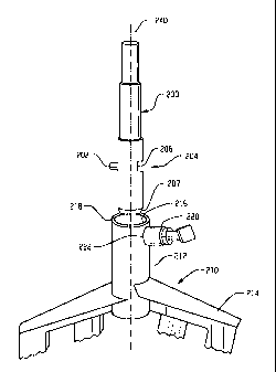
Appareil de mélange composé d'un corps possédant une partie mélange (214) et une partie accouplement (212). Cette dernière présente une ouverture supérieure conçue pour recevoir une tige et une ouverture latérale (224) conduisant à ladite ouverture. Celle-ci comporte un évidement (218) conçu pour loger un goujon (202) et placé diamétralement opposé à l'ouverture latérale, celle-ci étant située à une hauteur correspondant à au moins une partie de l'évidement recevant le goujon. Un élément de retenue (50) est accouplé mobile à la partie d'accouplement à travers l'ouverture latérale et sollicité dans une position tournée vers l'intérieur dans laquelle une partie intérieure de cet élément est normalement placée à l'intérieur de l'ouverture recevant la tige, cet élément de retenue étant mobile vers une position tournée vers l'extérieur dans laquelle la partie intérieure dudit élément de retenue est au moins partiellement placée en retrait par rapport à l'ouverture de réception de tige.


Abrégé anglais


A mixing implement includes a body having a mixing portion ( (214) and a
connecting portion (212) , the connecting portion having an upper shaft
receiving opening formed therein and a side opening (224) that leads to the
shaft receiving opening, the shaft receiving opening having a drive pin (202)
receiving recess (218) , the side opening and the drive pin receiving recess
located substantially diametrically opposite each other with the side opening
at a height corresponding to at least part of the drive pin receiving recess.
A retainer (50) is movably coupled with the connecting portion through the
side opening and biased into an inward position in which an inner portion of
the retainer is normally positioned within the shaft receiving opening, the
retainer movable to an outward position in which the inner portion of the
retainer is at least partially retracted from the shaft receiving opening.

Revendications

Note : Les revendications sont présentées dans la langue officielle dans laquelle elles ont été soumises.


5
Claims
[1] A mixer comprising:
a mixer body having a rotatable output shaft and a motor operatively coupled
to
the output shaft, the output shaft arranged to rotate around a shaft axis and
orbit
around another axis, the output shaft including a drive pin extending
sidewardly
therefrom and a retaining recess formed therein, the drive pin and the
retaining
recess on substantially diametrically opposed portions of the output shaft, a
distance from a lower end of the output shaft to the drive pin is
substantially the
same as a distance from the lower end of the output shaft to the retaining
recess;
a mixing implement having a connecting portion with a shaft receiving opening
having a drive pin receiving recess, a side opening located in the connecting
portion and leading to the shaft receiving opening, and a retainer coupled to
the
mixing implement for movement along the side opening between an inward
position in which at least part of said retainer is received in the retaining
recess
when the shaft is received in the shaft receiving opening to axially couple
the
mixing implement and the output shaft and a retracted position in which the
retainer retracts from the retaining recess to permit separation of the output
shaft
and the mixing implement.
[2] The mixer of claim 1 wherein the retainer comprises a spring-loaded
plunger
assembly with an external grip head.
[3] The mixer of claim 1 wherein the drive pin receiving recess includes side
chamfers for directing the drive pin into the drive pin receiving recess.
[4] The mixer of claim 1 wherein the drive pin receiving recess extends
through an
entire radial thickness of a wall of the connecting portion of the mixing
implement.
[5] The mixer of claim 1 wherein the retaining recess includes a substantially
flat
inward surface.
[6] The mixer of claim 1 wherein the retaining recess has a variable depth.
[7] A mixing implement for attachment to a mixer, the mixing implement
comprising:
a connecting portion and a mixing portion, the mixing portion extending
downward from the connecting portion, the connecting portion having an upper
shaft receiving opening formed therein and a side opening that leads to the
shaft
receiving opening, the shaft receiving opening having a single drive pin
receiving recess, the side opening and the drive pin receiving recess located
on
substantially diametrically opposite portions of the connecting portion with
the
side opening at a height corresponding to at least part of the drive pin
receiving

6
recess, the side opening spaced from a top of the connecting portion; and
a retaining pin movably coupled with the connecting portion through the side
opening, a spring positioned to bias the retaining pin into an inward position
in
which an inner end of the retaining pin is normally positioned within the
shaft
receiving opening, the retaining pin movable to an outward position in which
the
inner end of the retaining pin is at least partially retracted from the shaft
receiving opening, the retaining pin includes a gripping portion located
externally of the connecting portion for enabling manual retraction of the
retaining pin from the inward position to the outward position.
[8] The mixing implement of claim 7 wherein the drive pin receiving recess
includes
side chamfers for directing the drive pin into the drive pin receiving recess.
[9] The mixing implement of claim 7 wherein the drive pin receiving recess
extends
through an entire radial thickness of the connecting portion of the mixing
implement.
[10] A mixing implement for attachment to a mixer comprising:
a connecting portion and a mixing portion, the mixing portion extending
downward from the connecting portion, the connecting portion having an upper,
circumferential shaft receiving opening formed therein and a side opening that
leads to the circumferential shaft receiving opening, the circumferential
shaft
receiving opening having a drive pin receiving recess, the side opening and
the
drive pin receiving recess located on substantially diametrically opposite
portions
of the connecting portion with the side opening at a height corresponding to
at
least part of the drive pin receiving recess; and
a retainer movably coupled with the connecting portion through the side
opening
and biased into an inward position in which an inner portion of the retainer
is
normally positioned within the circumferential shaft receiving opening, the
retainer movable to an outward position in which the inner portion of the
retainer
is at least partially retracted from the circumferential shaft receiving
opening.
[11] The mixing implement of claim 10 wherein the drive pin receiving recess
includes side chamfers for directing the drive pin into the drive pin
receiving
recess.
[12] The mixing implement of claim 10 wherein the drive pin receiving recess
extends through an entire radial thickness of the connecting portion of the
mixing
implement.

Description

Note : Les descriptions sont présentées dans la langue officielle dans laquelle elles ont été soumises.


CA 02601947 2007-08-20
WO 2006/090349 PCT/IB2006/050609
1
Description
MIXER, MIXING IMPLEMENT AND ASSOCIATED
ATTACHMENT MECHANISM
TECHNICAL FIELD
[1] This application relates generally to an attachment mechanism or system
used with
a mixing machine and, more specifically, an attachment mechanism used for
connecting mixing implements to a rotatable output component of a mixing
machine.
BACKGROUND
[2] Mixers are used to mix and blend a variety of materials such as food
products. The
mixers typically include a removable mixing implement that is attachable to a
rotatable
and/or orbitable output shaft of the mixer. Mixing implements may come in
various
sizes and shapes and include agitators such as whips, dough hooks, beaters,
etc. The
mixing implements are typically removably coupled to the output shaft to
enable the
mixing implements to be removed or replaced for cleaning, repair, use of a
different
type of mixing implement, etc.
[3] One common type of attachment arrangement for mixing implements is a
bayonet
style connection. Alternative attachment arrangements are described in U.S.
Patent
Publication No. US 2002/0181322 Al. While the attachment arrangements in U.S.
Patent Publication No. US 2002/0181322 Al are useful, in some cases it may be
difficult to adapt such arrangements to smaller size mixers and smaller size
mixing
implements due to size and space limitations on smaller mixing implements
and/or
mixer shafts.
SUMMARY
[4] In one aspect, a mixing implement includes a body having a mixing portion
and a
connecting portion, the connecting portion having an upper shaft receiving
opening
formed therein and a side opening that leads to the shaft receiving opening,
the shaft
receiving opening having a drive pin receiving recess, the side opening and
the drive
pin receiving recess located substantially diametrically opposite each other
with the
side opening at a height corresponding to at least part of the drive pin
receiving recess.
A retainer is movably coupled with the connecting portion through the side
opening
and biased into an inward position in which an inner portion of the retainer
is normally
positioned within the shaft receiving opening, the retainer movable to an
outward
position in which the inner portion of the retainer is at least partially
retracted from the
shaft receiving opening.
BRIEF DESCRIPTION OF THE DRAWINGS
[5] Figs. 1-3 depict one embodiment of a mixing implement attachment system;

CA 02601947 2007-08-20
WO 2006/090349 PCT/IB2006/050609
2
[6] Fig 4 is an exploded, perspective cross sectional view of the actuator
assembly of
the embodiment of Figs. 1-3; and
[7] Fig. 5 shows an exemplary mixer construction.
DETAILED DESCRIPTION
[8] Referring now to Figs. 1-3, a mixing implement attachment system is shown.
In this
exemplary arrangement, the mixer output shaft 200 includes a drive pin 202
extending
outward therefrom and a recess 204. The drive pin 202 and recess 204 are
located at
substantially the same height or elevation along the length of the shaft 200
and are on
substantially diametrically opposite sides of the shaft 200. Illustrated
recess 204 does
not extend around the entire periphery of the shaft 200, and in one example
the recess
may be formed along approximately 45 to 60 circumferential degrees of the
shaft outer
surface. The illustrated recess 204 has a radial depth that varies relative to
a lon-
gitudinal axis 240 of the shaft 200, the recess 204 having a substantially
flat inward
surface 206 that results in the variable depth. However, the recess 204 could
also be of
uniform radial depth. Notably, the bottom portion of the shaft 200 includes a
tapered or
curved surface 207.
[9] The mixing implement 210 includes an upper connecting portion 212 and a
lower
mixing portion 214 (shown only in part). The configuration of the mixing
portion 214
can vary according to the type of mixing implement (e.g., a whisk, beater or
dough
hook etc.). The top of the connecting portion 212 includes un upper mixer
shaft
receiving opening 216 that in the illustrated embodiment has a circumferential
perimeter to match the circumferential shape of the mixer output shaft. A pin
receiving
recess 218 joins with the upper opening 216 and receives the drive pin 202
when the
shaft 200 is inserted in the opening 216. The mixing implement further
includes a
retaining mechanism 220 positioned substantially diametrically opposite the
pin
receiving recess 218. In one example the retaining mechanism may be formed by
a
plunger assembly similar to that shown in Fig. 4, which is described in detail
below,
the mechanism being inserted in a side opening 222 (Fig. 1) of the connecting
portion
212. As best seen in Fig. 3, an inner portion 224 of the side opening 222
communicates
with the upper opening 216 to permit an inward portion of the retaining
mechanism to
engage the shaft recess 204 when the mixing implement 210 is coupled to the
shaft
200. In such an arrangement the combination of the recess 204 and retaining
mechanism 220 vertically supports the mixing implement 210 on the shaft 200
and the
combination of the drive pin 202 and the recess 218 provides for torque
transfer from
the shaft 200 to the mixing implement 210.
[10] In the illustrated embodiment of Figs. 1-3 the pin receiving recess 218
extends
through an entire radial thickness of the wa11226 that defines the upper
opening 216.
However, non-through pin receiving recesses are contemplated. The upper entry

CA 02601947 2007-08-20
WO 2006/090349 PCT/IB2006/050609
3
portion of the pin receiving recess 218 may include side chamfers 228 to
facilitate
alignment of the shaft drive pin 204 into the recess 218 during the coupling
process.
Likewise, the shaft receiving opening 216 may include an entry chamfer 230 at
its
upper edge to facilitate proper alignment with the mixer shaft 200 during
coupling.
[ 11 ] Referring now to Fig. 4, the retaining mechanism 220 may take the form
of the il-
lustrated plunger or actuator assembly 50. The assembly 50 may include a
retainer or
plunger 54 having a generally cylindrical plunger shaft 56 and a generally
hemi-
spherical tip 58 defining a lip 84. The tip 58 of the plunger may also be
chamfered.
The actuator assembly 50 may also include a generally cylindrical casing 60
having a
central opening 61 defining a lip 82, with the central opening 61 being shaped
to
movably to receive the plunger 54 therein. The actuator assembly 50 may
further
include a spring 65 shaped to be disposed about the plunger shaft 56 and to be
received
inside the casing 60. The actuator assembly 50 may further include a button or
gripping portion 67 having a hollow stem 68 and an outer portion 70, with the
stem 68
being shaped and sized to receive the end of the plunger 54. The outer portion
70 may
have a pair of opposed flats 72. In order to assemble the actuator assembly
50, the
spring 65 is slid over the plunger shaft 56, and the plunger 54 and spring 65
are then
inserted to the central opening 61 of the casing 60. The plunger is then
inserted into the
stem 68 of the button 67. A coupling pin 76 is then passed through aligned
openings
78, 80 in the plunger shaft 56 and stem 68 to couple the plunger 54, casing 60
and
button 67 together. The spring 65 is captured in a compressed manner between
the lip
82 of the casing 60 and the lip 84 of the tip 58 of the plunger 54. In this
manner, in the
absence of outside forces, the tip 58 of the plunger 54 will protrude slightly
outwardly
from the casing 60 (e.g. to the right in the view of Fig. 4). The casing 60
includes
threads 631ocated on a portion of the outer surface thereof such that the
actuator
assembly can be threaded into the side opening 222 of the mixing implement 210
in a
secured but removable manner, enabling replacement if necessary.
[12] The embodiment of Figs. 1-3 may be particularly suited for smaller mixing
machines in which the size of the mixing implement 210 does not readily
provide for
having drive pin receiving slots located at different heights or elevations
than a
retaining mechanism. However, the configuration could be applied to any size
mixing
machine and mixing implement. During the coupling process the end of the mixer
shaft
200 may engage the inner portion of the retaining mechanism 220 to
automatically
move the retaining mechanism from its inward position toward its retracted
position.
More particularly, where the end of the mixer shaft 200 includes tapered
surface 207,
surface 207 may interact with the rounded or tapered surface of the tip 58 of
the
plunger 54, urging the plunger 54 to move outward from the shaft receiving
opening
216 against the biasing force of the spring 65. When the shaft recess 204
comes into

CA 02601947 2007-08-20
WO 2006/090349 PCT/IB2006/050609
4
alignment with the plunger 54, the spring bias causes the tip 58 of the
plunger 54 to
move into the recess 204 to vertically support the mixing implement 210 on the
shaft
200.
[13] Fig. 5 shows one embodiment of a mixer that could incorporate the mixing
implement attachment system described above. The mixer 10 has a mixer body 14
which houses a motor 11 therein. The motor 11 is operatively coupled to a
rotatable
and orbital output shaft 200 or output component. The mixer 10 further
includes a
mixing implement 210 that is attachable to the output shaft 200 such that
rotation and/
or orbital movement of the output shaft 200 can be transferred to the mixing
implement
210. During operation, the output shaft 200 and mixing implement 210 may
rotate
about their own axes and orbit about a central, upright bowl axis 250. The
mixer body
14 may include a yoke 18 for receiving a bow120 thereon, such that when the
bow120
is mounted on the yoke 18 and the mixing implement 210 is received in the
bow120,
the contents of the bow120 can be mixed by the rotating and/or orbiting mixing
implement 210.
[14] It is to be clearly understood that the above description is intended by
way of il-
lustration and example only and is not intended to be taken by way of
limitation, and
that changes and modifications are possible. Accordingly, other embodiments
are con-
templated.

Dessin représentatif
Une figure unique qui représente un dessin illustrant l'invention.
États administratifs

2024-08-01 : Dans le cadre de la transition vers les Brevets de nouvelle génération (BNG), la base de données sur les brevets canadiens (BDBC) contient désormais un Historique d'événement plus détaillé, qui reproduit le Journal des événements de notre nouvelle solution interne.

Veuillez noter que les événements débutant par « Inactive : » se réfèrent à des événements qui ne sont plus utilisés dans notre nouvelle solution interne.

Pour une meilleure compréhension de l'état de la demande ou brevet qui figure sur cette page, la rubrique Mise en garde , et les descriptions de Brevet , Historique d'événement , Taxes périodiques et Historique des paiements devraient être consultées.

Historique d'événement

Description Date
Représentant commun nommé 2019-10-30
Accordé par délivrance 2010-05-11
Inactive : Page couverture publiée 2010-05-10
Inactive : Taxe finale reçue 2010-02-22
Préoctroi 2010-02-22
Un avis d'acceptation est envoyé 2009-08-24
Lettre envoyée 2009-08-24
Un avis d'acceptation est envoyé 2009-08-24
Inactive : Approuvée aux fins d'acceptation (AFA) 2009-08-19
Inactive : Déclaration des droits - Formalités 2007-11-19
Inactive : Page couverture publiée 2007-11-06
Lettre envoyée 2007-11-02
Inactive : Acc. récept. de l'entrée phase nat. - RE 2007-11-02
Inactive : CIB en 1re position 2007-10-23
Demande reçue - PCT 2007-10-22
Exigences pour l'entrée dans la phase nationale - jugée conforme 2007-08-20
Exigences pour une requête d'examen - jugée conforme 2007-08-20
Toutes les exigences pour l'examen - jugée conforme 2007-08-20
Demande publiée (accessible au public) 2006-08-31

Historique d'abandonnement

Il n'y a pas d'historique d'abandonnement

Taxes périodiques

Le dernier paiement a été reçu le 2010-02-02

Avis : Si le paiement en totalité n'a pas été reçu au plus tard à la date indiquée, une taxe supplémentaire peut être imposée, soit une des taxes suivantes :

  • taxe de rétablissement ;
  • taxe pour paiement en souffrance ; ou
  • taxe additionnelle pour le renversement d'une péremption réputée.

Veuillez vous référer à la page web des taxes sur les brevets de l'OPIC pour voir tous les montants actuels des taxes.

Titulaires au dossier

Les titulaires actuels et antérieures au dossier sont affichés en ordre alphabétique.

Titulaires actuels au dossier
PREMARK FEG L.L.C.
Titulaires antérieures au dossier
JANICE J. SCHNIPKE
NEAL H. BLACKBURN
Les propriétaires antérieurs qui ne figurent pas dans la liste des « Propriétaires au dossier » apparaîtront dans d'autres documents au dossier.
Documents

Pour visionner les fichiers sélectionnés, entrer le code reCAPTCHA :


Pour visualiser une image, cliquer sur un lien dans la colonne description du document. Pour télécharger l'image (les images), cliquer l'une ou plusieurs cases à cocher dans la première colonne et ensuite cliquer sur le bouton "Télécharger sélection en format PDF (archive Zip)" ou le bouton "Télécharger sélection (en un fichier PDF fusionné)".

Liste des documents de brevet publiés et non publiés sur la BDBC .

Si vous avez des difficultés à accéder au contenu, veuillez communiquer avec le Centre de services à la clientèle au 1-866-997-1936, ou envoyer un courriel au Centre de service à la clientèle de l'OPIC.


Description du
Document 
Date
(aaaa-mm-jj) 
Nombre de pages   Taille de l'image (Ko) 
Description 2007-08-20 4 224
Abrégé 2007-08-20 2 73
Dessins 2007-08-20 4 69
Revendications 2007-08-20 2 109
Dessin représentatif 2007-08-20 1 9
Page couverture 2007-11-06 2 45
Dessin représentatif 2010-04-20 1 7
Page couverture 2010-04-20 2 46
Paiement de taxe périodique 2024-02-23 47 1 942
Accusé de réception de la requête d'examen 2007-11-02 1 177
Rappel de taxe de maintien due 2007-11-05 1 113
Avis d'entree dans la phase nationale 2007-11-02 1 204
Avis du commissaire - Demande jugée acceptable 2009-08-24 1 162
PCT 2007-08-20 2 71
Correspondance 2007-11-02 1 26
Correspondance 2007-11-19 3 98
Correspondance 2010-02-22 1 39