Note: Descriptions are shown in the official language in which they were submitted.
CA 02602033 2007-09-24
1
Device for detecting and displaying the position of components of vehicle
couplings
Description
The invention relates to a device for detecting and displaying the position of
components of
vehicle couplings, in particular, fifth-wheel couplings. The invention also
relates to an
arrangement of such a device on the exterior of fifth-wheel couplings or of
displacement devices
of a fifth-wheel coupling.
From DE 102 41 904 Al, a device for displaying the closure state of a fifth-
wheel coupling is
known, wherein a first sensor is arranged in the area of the receptacle
opening of the fifth-wheel
coupling and detects the kingpin and a second sensor comprises a magnetically
sensitive sensor,
which interacts with a magnet mounted on an operating lever, wherein the two
sensors rely on
different actuating mechanisms. These sensors are connected to a display unit
in the driver's cab
of the semi-trailer tractor truck.
The signal transmission, as well as the power supply for the sensors, is
usually realized via cable
sets and the signal evaluation is realized via corresponding control
electronics. The installation
expense for such systems is large and often stands in poor relationship to the
achieved effect,
which hinders greater circulating use of these systems for desirable safety
equipment.
From US 6,736,420 B2, a displacement device for fifth-wheel couplings is
known, which has
two guide rails with toothed racks, on which a carriage carrying the fifth-
wheel coupling is
CA 02602033 2007-09-24
2
supported so that it can be displaced. A locking device with blocking parts
engaging in the
toothed racks is arranged on the carriage. One of the blocking parts is
connected to an opening
lever, which, in turn, can be connected to an actuation device, e.g., a pull
lever, for manual
actuation. In this known displacement device, it is also necessary for the
driver to visually
inspect the proper locking of the carriage before he drives away.
Independent of the presence of display devices in the driver's cab, the driver
must perform a
visual inspection of the vehicle, the fifth-wheel coupling, the closing
device, etc. before
beginning to drive.
Usually, mechanical closure displays are used, which can be easy or hard to
read according to
their construction and the lighting conditions. This can make the vehicle
check significantly
more difficult before starting the drive and in the extreme case can even lead
to incorrect
coupling.
Therefore, the problem of the invention is to present a device for detecting
and displaying the
position of components of vehicle couplings, which makes a visual inspection
of these
components easier.
This problem is solved with a device, which is characterized by a combined
sensor and display
unit arranged in a common housing, wherein the sensor unit has at least one
sensor and the
display unit has at least one display element.
CA 02602033 2007-09-24
3
The advantage of the device is that a compact unit is made available, which
can be placed at the
location of the check and also outputs there a preferably optical or acoustic
signal. Complicated
wiring of the sensor unit with a display device arranged in the driver's cab
is eliminated.
Therefore, an economical unit is made available, which can be arranged without
a problem at
positions, where a check is to be performed. The visual check can be performed
by the driver
while passing by, without requiring the need of additional aids, e.g.,
flashlights, etc., in order to
check, for example, the closure state of a fifth-wheel coupling or the
position of a displacement
device.
Preferably, the combined sensor and display unit has its own voltage source,
which is preferably
arranged in the housing. This measure also contributes to the universal use of
the device
according to the invention. Wiring to the voltage source is eliminated.
Batteries, accumulators,
or, e.g., electrokinetic generators can be used as the voltage source.
Preferably, the combined sensor and display unit has an electronic evaluation
unit. With this
evaluation unit, not only can the sensor signal be evaluated to the extent
whether a closure state
is present or not (yes/no signal), but such an evaluation unit also allows the
state of the voltage
source (e.g., accumulator or battery) to be evaluated.
Preferably, the device can also have at least one distance sensor. With a
device equipped with
such a distance sensor, it is possible, for example, for a fifth-wheel
coupling, to check the correct
position of a semi-trailer on the fifth-wheel coupling. With reference to the
determined distance
from the device to the bottom side of the semi-trailer, it can be determined
whether this is located
CA 02602033 2007-09-24
4
in the prescribed position, in which the kingpin engages in the closing device
of the fifth-wheel
coupling.
The sensors can be inductive sensors, magnetic sensors, force sensors,
pressure sensors, or reed
sensors. Preferably, the sensors operate using a contact-less method, wherein
electromagnetic
sensors are preferred.
According to the location of use, the sensor can also have a switch element,
in particular, a
mechanical switch element. Such a construction is preferred, for example, in
the use of the
device according to the invention on bolt couplings.
The display unit preferably has an optical display element arranged on the
housing. This can be,
e.g., a lamp, especially an LED display. Here, it is preferred when this
optical display element is
arranged on the housing, such that it can be read without a problem by the
driver when he walks
by according to the position of the device on the vehicle.
The display unit can have exclusively or additionally an acoustic display
element and/or a
mechanical display element. Mechanical display elements can be direction
indicators, pins, or
the like. Beepers or buzzers are preferred for the acoustic display elements.
The display on the
display element can be continuous, for example, by means of a continuous light
or continuous
tone. The display, however, can also be not continuous and can be, e.g., in
the form of a blinking
light or the like.
CA 02602033 2007-09-24
It is provided, in particular, to display the closure state, e.g., of a fifth-
wheel coupling, by an
optical or acoustic signal. It can also be preferred to display the open
position according to a
signal. The sort of display that is selected depends on the sort of position
to be detected for the
vehicle components and/or on their arrangement on the vehicle.
The arrangement according to the invention of the described device provides
that the device is
arranged on the exterior of a fifth-wheel coupling or of a displacement device
of a fifth-wheel
coupling and adjacent to a manual actuation element of a closing or locking
device, wherein a
contact element of this type is arranged on the manual actuation element or
can be actuated by
the manual actuation element, so that it interacts with the sensor of the
sensor unit in the closed
or locked position.
The exterior of a fifth-wheel coupling or of a displacement device means a
suitable location that
can be seen easily from the outside, so that the display device can be easily
read while walking
past the vehicle. The arrangement on or in the vicinity of a manual actuation
element offers the
advantage that here it involves a location, which must otherwise be accessible
for the driver,
because he must actuate the manual actuation element, for example, for locking
a fifth-wheel
coupling. Such locations are easy to see, so that the device or its display
device can be read there
without a problem.
The manual actuation element can be a pull lever or a safety lever of a pull
lever.
CA 02602033 2007-09-24
6
As the contact element, a metal plate or a magnet is preferred, which is
attached to the manual
actuation element. By moving the manual actuation element, this contact
element moves into the
area of the sensor of the device or away from the sensor, so that two
different positions of the
manual actuation element and thus also of the locking device connected to this
element can be
detected.
The contact element can also be arranged on a pivot element, which is a manual
actuation
element. Such a manual actuation element is used, for example, as a locking
element for a pull
lever, with which the closing device of a fifth-wheel coupling is actuated.
The contact element
interacts with the sensor of the device when it is pivoted into the area of
the sensor.
The device according to the invention can also be arranged on the exterior of
a bolt coupling
adjacent to the coupling bolt, which interacts with the sensor of the sensor
unit in the closed
position.
In this construction, the sensor has a switch element, which can be actuated
by the coupling bolt.
This switch element is linked with the sensor unit, such that the closure
state of the bolt coupling
can be determined from the position of the switch element.
Another arrangement of the device provides the attachment to the exterior of a
displacement
device, which has a toothed rack and blocking parts on a carriage carrying a
fifth-wheel
coupling, and adjacent to a blocking part, which interacts in the locked
position with the sensor
of the sensor unit. It is possible with the device to display the exact
position of the displacement
CA 02602033 2012-02-27
7
device, i.e., of the carriage, on site and in position. For this purpose, the
display device
can have several display elements or also a digital or analog display, which
gives the
position, for example, in centimeters from a fixed point.
In accordance with an aspect of the present invention there is provided an
arrangement of
a device on an exterior of a fifth-wheel coupling or of a displacement device
of a fifth-
wheel coupling and adjacent to a manual actuation element of a closing or
locking device,
wherein the device has a combined sensor and display unit arranged in a common
housing, wherein the sensor unit has at least one sensor and the display unit
has at least
one display element, and wherein a contact element is arranged on the manual
actuation
element or can be actuated by the manual actuation element, such that it
interacts in a
closed or locked position with the sensor of the sensor unit.
In accordance with a further aspect of the present invention there is provided
an
arrangement of a device on the exterior of a bolt coupling adjacent to the
coupling bolt,
which interacts in the closed position with the sensor of the sensor unit,
wherein the
device has a combined sensor and display unit arranged in a common housing,
wherein
the sensor unit has at least one sensor and the display unit has at least one
display element
and wherein the sensor has a switch element, which can be actuated by the
coupling bolt.
In accordance with a further aspect of the present invention there is provided
an
arrangement of a device on the exterior of a displacement device which has a
toothed rack
and blocking parts on a carriage carrying a fifth-wheel coupling, and adjacent
to a
blocking part which interacts in a locked position with a sensor of a sensor
unit, wherein
the device has a combined sensor and display unit-arranged in a common
housing,
wherein the sensor unit has at least one sensor and the display unit has at
least one display
element.
In accordance with a further aspect of the present invention there is provided
a device for
detecting and displaying the position of components of vehicle couplings, in
particular, of
fifth-wheel couplings, wherein a combined sensor and display unit is arranged
in a
common housing, the sensor unit having at least one sensor and the display
unit having at
least one display element, and wherein the combined sensor and display unit
has its own
separate voltage source.
CA 02602033 2012-02-27
7a
Example embodiments of the invention are explained in more detail below with
reference
to the drawings. Shown are:
Figure 1 a schematic view of the device according to the invention,
Figures 2 and 3 the arrangement of the device according to the invention on a
fifth-
wheel coupling according to a first embodiment,
Figures 4 and 5 the arrangement of the device according to the invention on a
fifth-
wheel coupling according to a second embodiment,
Figures 6 and 7 the arrangement on a fifth-wheel coupling according to a third
embodiment,
Figure 8 the arrangement of the device on a bolt coupling,
Figures 9a and 9b an enlarged schematic view of the device on a bolt coupling,
Figures 10 and 11 the arrangement of the device according to the invention on
a
displacement device.
CA 02602033 2007-09-24
8
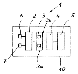
In Figure 1, the device 1 according to the invention is shown schematically. A
housing 10 shown
with dashed lines accommodates a sensor unit 3 with sensors 3a, 3b, a display
unit 2, an
evaluation unit 4, a voltage source 5, and display elements 6 and 7, which are
connected to the
display unit 2. All of the units are connected to the voltage source 5 and
also partially connected
to each other, which is shown only schematically in Figure 1. The shown device
1 contains both
an acoustic display element 6 and also an optical display element 7.
In Figure 2, the arrangement of such a device 1 on a fifth-wheel coupling 20
is shown. The side
wall 25 of a coupling plate has a passage opening 26, in order to lead the
pull lever 21 to the
outside. This pull lever 21 is connected via a rod assembly to a closing
device for the kingpin,
which cannot be seen in the view shown here.
The pull lever 21 has a handle 24, with which the pull lever can be moved in
the direction of the
arrow. A safety lever 22, which also extends outwardly through the opening 26
and which is
connected by means of a spring 23 in the area of the handle 24, is arranged
adjacent to the pull
lever 21.
The device 1 is arranged in the passage opening 26, wherein the sensor of the
device 1 is
provided on the bottom side of the housing 10 and therefore is not visible.
Because the pull lever
21 is located under the device 1, this preferably has on its top side a
contact element 12 in the
form of a metal plate 13. Instead of a metal plate, a magnet can also be used.
In Figure 2, this
CA 02602033 2007-09-24
9
metal plate is located under the sensor. This is the position, in which the
closing device is located
in the closed position and the pull lever 21 is located in its safety
position.
By pulling out the pull lever 21, this lever is moved into a position that
allows the pull lever to
also be displaced laterally and to open the closing device of the kingpin. In
this way, the contact
element 12 moves away from the device 1 and thus from the sensor, which can be
indicated by
the display device.
In Figures 2 and 3, it is provided that the display device has an optical
display element 7, which
is illuminated when the closed position is set (Figure 2) and is turned off
when the pull lever is
moved into the open position (Figure 3). The optical display element 7 is
mounted on the
housing 10 on the side and thus can be seen from the operating side.
In Figure 4 another embodiment is shown. In this construction, the device 1 is
also arranged on
the peripheral wall 25 on the fifth-wheel coupling plate 20. The safety lever
30 is a separate
lever, which is not connected to the pull lever 21. On the top side of the
safety lever 30, the
contact element 12 is also arranged in the form of a metal plate 13. Before
the pull lever 21 can
be moved, the safety lever 30 must first be shifted, as shown in Figure 5.
Only then is it possible
to move the pull lever 21 for opening the closing device over the safety hook
31 on the safety
lever 30.
In Figures 6 and 7, another embodiment is shown. On the peripheral wall 25 of
the fifth-wheel
coupling 20, a pivot bearing 27 is provided, in which a pivot lever 14 is
supported with a contact
CA 02602033 2007-09-24
element 12 mounted on this pivot lever and thus secures the pull lever 21. The
device 1
according to the invention, which has a sensor on the bottom side, is arranged
above the pivot
lever 14. In the position shown in Figure 6, the pull lever 21 and thus the
closing device is
located in the closed position. Accordingly, the optical display 7 is
illuminated.
Before the pull lever 21 can be moved for opening the closure, the pivot lever
14 must be pivoted
in the pivot bearing 27 by 90 , so that the concerned leg of the pivot lever
is moved away from
the sensor of the sensor unit of the device 1. The device 1 therefore
recognizes the open position
and the display element 7 is turned off.
Furthermore, in Figures 6 and 7, a distance sensor 3b is to be seen, which is
arranged on the top
side of the housing and which detects the distance to a coupled semi-trailer
(not shown).
In Figure 8, a bolt coupling 40 is shown, which has a coupling housing 41,
into which the front
end, for example, of a drawbar, can be introduced. In the housing there is an
opening for the
coupling bolt 44, which can be shifted in the perpendicular direction. The
lever 43 is provided
for this purpose.
The device 1 according to the invention is arranged with the display element 7
on the left side of
the coupling housing 41. The function is shown in Figures 9a and 9b.
The device 1 has a mechanical switch element in the form of a safety bolt 18
with the contact
element 12 on its free end, which is arranged spring-mounted on the housing 1
and which
CA 02602033 2007-09-24
11
extends outwardly through the housing 10. Figure 9a shows the opened position
of the coupling
bolt 44. Figure 9b shows the closed position, in which the coupling bolt 44 is
shifted relative to
the safety bolt 18, so that the safety bolt 18, driven by the pressure spring
19, is lowered into a
recess in the coupling bolt 44. The corresponding position can be recognized,
besides with
reference to the optical display element 7, also with reference to the
position of the safety bolt
18, as a comparison of Figures 9a and 9b shows. Therefore, it is possible to
detect the locked
position of the coupling bolt 44.
In Figures 10 and 11, a displacement device 50 is shown. Guide rails 54 with
toothed racks 51
and teeth 55 arranged parallel to each other are mounted on a tractor truck
(not shown). The teeth
55 are arranged pointing inward and lie in a common plane.
A carriage 70, whose frame is not shown in Figures 10 and 11, is displaceably
arranged on the
guide rails 54.
On the carriage, a locking device with blocking parts 52a, b is arranged,
which are connected to a
pull lever 61 via levers 53a, b. By means of the pull lever 61, these blocking
parts 52a, b are
shifted from an unlocked position (Figure 10) into a locked position (Figure
11) and vice versa.
The device 1 according to the invention is arranged on a wall element 58,
through which the pull
lever 61 is guided. A contact element 12 is arranged on the top side of the
pull lever 61. In Figure
10, which shows the unlocked position, the pull lever 61 is fixed with its
catch recess 62 on the
wall element 58. The contact plate 12 is arranged outside of the device 1, so
that the device 1
detects the unlocked position.
CA 02602033 2007-09-24
12
When the pull lever 61 is pushed in, as shown in Figure 11, and the blocking
parts 52a, b assume
their locked position, the contact element 12 is moved under the device 1, so
that this device can
detect the locked position with the sensor unit. A corresponding signal is
displayed via the
optical display 7.
In Figures 10 and 11, a device 1', which has three position sensors 3c on the
inside and three
optical displays 7' on the outside, is arranged on the toothed rack 51. When
the teeth 56 of the
blocking part 52a engage in the gaps between the teeth 55 of the toothed rack
51, this is detected
by the position sensors 3c. When the carriage 70 is shifted, the position of
the blocking parts 52a,
b changes, so that not all of the teeth 56 of the blocking part 52a lie
opposite a position sensor 3c.
The optical display elements 7' are illuminated according to whether only one
sensor 3c or two
or all three sensors 3c detect teeth 56. When walking past, the driver can
recognize in which
position the carriage of the displacement device is located with reference to
the number of
illuminated display elements.
CA 02602033 2007-09-24
13
List of reference symbols
1, 1' Device
2 Display unit
3 Sensor unit
3a Sensor
3b Sensor (distance sensor)
3c Sensor (position sensor)
4 Evaluation unit
Voltage source
6 Acoustic display element
7 Optical display element
Housing
12 Contact element
13 Metal plate
14 Pivot element
17 Switch element
18 Safety bolt
19 Pressure spring
Fifth-wheel coupling
21 Pull lever
CA 02602033 2007-09-24
14
22 Safety lever
23 Spring
24 Handle
25 Peripheral wall
26 Opening
27 Pivot bearing
30 Safety lever
31 Safety hook
40 Bolt coupling
41 Coupling housing
43 Safety lever
44 Coupling bolt
50 Displacement device
51 Toothed rack
52a, b Blocking part
53a, b Lever
54 Guide rail
55 Tooth
56 Tooth
57 Spring
CA 02602033 2007-09-24
58 Wall element
61 Pull lever
62 Catch recess
63 Catch arrangement
64 Handle
66 Tooth
70 Carriage