Note: Descriptions are shown in the official language in which they were submitted.
CA 02602703 2007-09-26
WO 2006/103293 PCT/EP2006/061253
Description
METHOD FOR THE PRODUCTION OF METAL CLOSURES
Technical Field
[001] The present invention relates to an improved method for manufacturing
metal
closures and enhanced tooling for carrying out such a method. In particular,
the
method is applied to the production of a metal closure from a closure shell,
which has a
shape adapted to reduce or eliminate the incidence of so called "angel hair".
[002] Metal closures to which the invention is applied are made from sheet
metal (for
example, steel or aluminium), to which a thin polymer coating is applied.
Closure
shells are produced from sheets of the polymer-coated metal by stamping, which
si-
multaneously shapes and cuts the closure blank using a co-operating punch and
die.
Problems have been encountered during the stamping process, because thin
slivers of
the polymer coating are formed where the sheet of polymer-coated metal is cut.
These
slivers are conventionally referred to as "angel hairs" and are visually
unattractive.
During later forming steps (for example, the formation of a curl at the cut
metal edge)
such "angel hairs" may become detached from the closure shell and form
"fluff',
which interferes with the forming machinery.
[003] Conventionally, the process for production of a metal closure includes
the following
steps: Stamping a closure blank from a coated metal sheet in a press (having
first and
second parts, which move relative to one another); separating the press parts
and
ejecting the metal blank from one of the parts; and pre-curling the cut edge
of the
closure blank to form the start of an internal peripheral curl at the cut edge
thereof.
These steps may be carried out in the same tool or alternatively stamping and
pre-
curling may be carried out in separate tools. The pre-curled blank is then
transferred to
a curling tool, in which the cut edge of the metal shell is formed into a
tight internal
curl. Between the various production stages described above, the closure blank
must be
transported between tools by a transfer system.
Background Art
[004]
WO 2005023451 (MAIKO ENGINEERING GMBH.). 2005-03-17.
proposes a metal closure blank, which has an external radius adjacent to its
cut edge.
This external radius has been found to prevent the formation of "angel hairs".
However, at production speeds (about 1200 closures per minute), the external
radius
causes a number of problems with conventional tooling.
[005] Conventional closure blanks have a cylindrical side-wall, which closely
matches the
side-wall of the cavity in the press and thus, the closure blank is retained
in the cavity
CA 02602703 2007-09-26
WO 2006/103293 PCT/EP2006/061253
2
until the press parts are separated and the part carrying the closure blank
reaches "top
dead centre". Once this position is reached, the closure blank is ejected from
the press
by means of "press air". Where the closure blank has an external radius (to
prevent the
formation of "angel hairs"), the external radius creates a looser seat in the
press cavity
and interferes with press air as the press parts are separated after formation
of the
closure blank. Thus, the closure blank tends to twist uncontrollably and fall
out of the
press as the press parts are separated.
[006]
WO 200249787 (DAYTON SYSTEMS GROUP, INC.). 2002-06-27.
describes a press arrangement suitable for production of metal closure blanks
(closure
cup) having such an outward curled rim. The metal closure blank (closure cup)
is
biased against part of the forming punch by a first airstream introduced into
the cavity
within the underside of the cap. As the punch reaches "top dead centre", the
blank
(closure cap) is ejected from the punch by a second airstream.
[007] A further problem is encountered during transport of the closure blanks
between
production stages. An air transport system is conventionally used for this
purpose, in
order to increase production speeds. Known air transport systems comprise a
base
plate, sidewalls and a top plate and an air stream passes through the volume
so defined,
carrying the closure blanks on a cushion of air. When closure blanks having an
external radius at their cut edge are transported in such an air transport
system, the air
flow catches under the external radius and tends to flip or tilt the closure
blanks. Thus,
such closure blanks "dance" around uncontrollably in the air stream and jostle
one
another, damaging the thin polymer coating thereon.
[008]
US 4655677 (PRECISION METAL FABRICATORS, INC.). 1987-04-07.
describes a similar problem, encountered when trying to transport container
ends
through such a conventional air conveyor system. This patent describes how
stacks of
container ends may be successfully transported in an air conveyer system. In
this
system, the top cover of the conveyor is spaced above the stack of container
ends at a
height which is less than the overlap of the nested container ends, thereby
ensuring that
the container ends remain in their respective stacks when subjected to lateral
forces.
Disclosure of Invention
[009] Before the closure blank passes to the curling stage of the production
process, the
external radius must be removed and the closure sidewall straightened before a
tight
inward curl may be formed on the closure shell. It has been proposed that such
straightening may be most easily achieved in a further stamping operation, but
this
process may exacerbate the tendency of the closure blank to form an external
curl.
CA 02602703 2007-09-26
WO 2006/103293 PCT/EP2006/061253
3
[O10] Accordingly, the inventors propose straightening the outward radius on
the closure
blank by rolling the closure blank about its main axis along a tool having a
flat surface
parallel to the sidewall of the closure blank. Thus, the external radius on
the closure
blank is progressively unfurled and accidental external curling is prevented.
The
inventors have modified the conventional pre-curl tool to provide a straight
wall
portion to gently straighten the sidewall of the closure before gently urging
the cut
edge of the closure sidewall into an inward curl. Subsequent curling tools may
then be
used to tighten the inward curl, thereby creating a closure having a tight
inward curl at
its free peripheral edge. The flat portion of the tooling follows a gentle
radius over a
length greater than the external circumference of the closure shell. This
ensures that the
closure shell makes one complete rotation against the straightening portion of
the tool
and that the closure shell has a cylindrical, straight-sided configuration,
before entering
tooling (or portion of the tool) adapted to urge formation of an inward curl.
Brief Description of the Drawings
[O11] The present invention will now be described, by way of example only,
with
reference to the accompanying drawings, in which:
FIGURE 1 shows a cross section view of a press suitable for forming a modified
closure blank having an external radius at its peripheral free edge to
mitigate the
production of "angel hair" upon cutting.
FIGURE 2 shows a cross section view through a conventional air transport
system
with a conventional closure blank (left) and modified closure blank (right)
carried
therein, illustrating the tipping effect of the airflow on the external radius
of the
modified closure.
FIGURE 3 shows a cross section view through a modified air transport system
with a
modified closure carried therein.
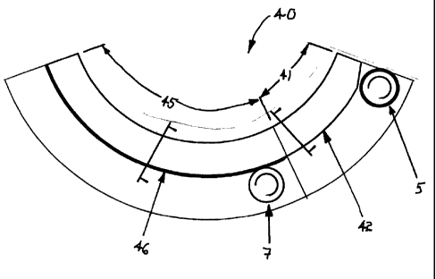
FIGURE 4 shows a conventional pre-curling rail for starting the inward curl on
a
cylindrical wall closure blank.
FIGURE 5 shows a modified pre-curling rail having a straightening portion and
a pre-
curl portion for straightening the external radius on a modified closure and
for forming
the start of the inward curl.
[012] Wherever possible in the drawings like reference numerals have been used
to
designate similar parts.
[013] Referring to FIGURE 1, a modified closure blank 1 is stamped from a
sheet of steel
having a thin polymer coating in a press 10 having at least two press parts
11, 12,
which are capable of movement relative to each other. The closure blank 1 has
a
cylindrical sidewall and an external radius 6. Clamp holder 15 accommodates
the
external radius 6 and the press part 11 is lowered due to the reduced height
of the
CA 02602703 2007-09-26
WO 2006/103293 PCT/EP2006/061253
4
closure blank 5. The radius of the external cur16 and the height of the
modified closure
blank 5 must be optimised to ensure that "angel hair" is avoided. Such
modification
requires consequential modification to the press parts. For example, the
"knock out"
stem 16 must be lengthened / lowered to allow it to kick the closure blank 5
out of the
cavity, when the press parts 11, 12 are separated and have reached the pres-
defined
position. Modification of the height of the modified closure blank 5 by just
0.1mm may
affect whether or not "angel hairs" are produced.
[014] As illustrated diagrammatically in FIGURE 2 whilst conventional closure
blanks 1
are carried through an air transport system 30 on a cushion of air, the air
flow
interferes with the external radius on a modified closure blank 5 and tends to
lift and
tilt to closure blank 5, causing it to jostle amongst adjacent blanks. This
affects the
flow of the production process and also results in damage to the closure
blanks 5.
[015] Referring now to FIGURE 3, the transfer of modified closure blanks 5 in
an air
transport system 30 may be brought under control if the spacing h between the
top 38
and bottom 31 of the air transport conduit is restricted. This is particularly
true, if the
headspace h' is less than 0.5 mm above the top of the closure blank 5.
[016] Despite the disclosure in
WO 200249787 (DAYTON SYSTEMS GROUP, INC.). 2002-06-27.
many conventional metal closures for foodstuffs have an internal curl at their
peripheral edge. Thus, before an inward curl may be produced on a modified
closure
blank 5 (having an external radius 6) the sidewall of the closure must first
be
straightened. The inventors have proposed a modification to the initial
segment of the
pre-curling tooling 40 (shown in FIGURE 4) to achieve this.
[017] Referring to FIGURE 5, the pre-curling too140 according to the invention
is
divided into two portions. The first portion 41 has a straight sided wall 42,
which is
used to gently straighten the external cur16 as the modified closure blank 5
is rolled
against the tool. Portion 41 is of sufficient length to ensure that the
closure blank 5
makes at least one complete rotation about its main axis to ensure that the
side wall
thereof is reformed into a straight sided cylindrical side wall. The reformed
closure
blank 7, then rolls against the second portion 45 of the tool, which has a pre-
curling
rai146 to gently urge the cut edge of the reformed closure blank 7 towards an
inward
curl.
[018] The closure blank 5 may then be transferred to the first of a series of
curling tools,
used to form a tight inward curl at the peripheral, cut edge of the closure
shell.