Language selection

Search

Patent 2602780 Summary

Third-party information liability

Some of the information on this Web page has been provided by external sources. The Government of Canada is not responsible for the accuracy, reliability or currency of the information supplied by external sources. Users wishing to rely upon this information should consult directly with the source of the information. Content provided by external sources is not subject to official languages, privacy and accessibility requirements.

Claims and Abstract availability

Any discrepancies in the text and image of the Claims and Abstract are due to differing posting times. Text of the Claims and Abstract are posted:

  • At the time the application is open to public inspection;
  • At the time of issue of the patent (grant).
(12) Patent: (11) CA 2602780
(54) English Title: DIRECTIONALLY-ADJUSTABLE LED SPOTLIGHT
(54) French Title: PROJECTEUR A DEL REGLABLE EN DIRECTION
Status: Granted
Bibliographic Data
(51) International Patent Classification (IPC):
  • F21V 29/77 (2015.01)
  • F21V 29/89 (2015.01)
  • F21K 9/233 (2016.01)
  • F21V 14/02 (2006.01)
  • F21V 21/30 (2006.01)
(72) Inventors :
  • WALCZAK, STEVEN R. (United States of America)
  • WILCOX, KURT (United States of America)
  • GUILLIEN, WAYNE (United States of America)
(73) Owners :
  • IDEAL INDUSTRIES LIGHTING LLC (United States of America)
(71) Applicants :
  • RUUD LIGHTING, INC. (United States of America)
(74) Agent: BERESKIN & PARR LLP/S.E.N.C.R.L.,S.R.L.
(74) Associate agent:
(45) Issued: 2014-06-17
(22) Filed Date: 2007-09-18
(41) Open to Public Inspection: 2008-03-30
Examination requested: 2011-09-06
Availability of licence: N/A
(25) Language of filing: English

Patent Cooperation Treaty (PCT): No

(30) Application Priority Data:
Application No. Country/Territory Date
11/541,906 United States of America 2006-09-30

Abstracts

English Abstract

The inventive directionally-adjustable LED spotlight is comprised of a fixed heat sink and an LED-array-bearing structure. The LED-array-bearing structure is adjustably attached in a heat transfer relationship to the fixed heat sink.


French Abstract

Un projecteur innovateur à DEL réglable en direction comprend un dissipateur de chaleur fixe et une structure porteuse d'un réseau de DEL. La structure porteuse d'un réseau de DEL est fixée de manière réglable dans une relation de transfert de chaleur au dissipateur de chaleur fixe.

Claims

Note: Claims are shown in the official language in which they were submitted.


CLAIMS

We claim:

1. A directionally-adjustable LED spotlight comprising a fixed heat sink
with an
arcuate interior surface, and a plurality of LEDs on a ball shaped LED array
bearing structure
with an arcuate exterior surface adjustably attached within the heat sink and
in
complementary direct heat transfer relationship therewith wherein the LED-
array-bearing
structure and heat sink are of a ball and socket design wherein the LED-array-
bearing
structure is the ball and the heat sink is the socket.
2. The directionally-adjustable LED spotlight of claim 1 wherein the ball-
shaped
LED-array-bearing structure is hollow.
3. The directionally-adjustable LED spotlight of claim 2 further comprising
a
retention assembly for releasably securing the ball shaped LED array-bearing
structure in
relation to the socket shaped heat sink.
4. The directionally-adjustable LED spotlight of claim 3 wherein the
retention
assembly comprises a collar releasably secured along an upper edge of the
fixed heat sink.
5. The directionally-adjustable LED spotlight of claim 4 wherein the collar

comprises multiple sections.
6. The directionally-adjustable LED spotlight of claim 1, wherein the LED
array
includes a first side with the LEDs and a second side, opposite the first
side, and
wherein the LED-array-bearing structure includes a platform portion
corresponding in
size to the second side of the LED array , the platform portion for receiving
the LED array
whereby the second side of the LED array is in contact with the platform
portion.
7. The directionally-adjustable LED spotlight of claim 6 where the ball
portion
of the LED-array-bearing structure and the heat sink are made from a heat-
conducting
material.

-5-


8. The directionally-adjustable LED spotlight of claim 7, wherein the heat-
conducting material is metal.
9. The directionally-adjustable LED spotlight of claim 8, wherein the heat
sink
includes a plurality of fins extending outwardly from a side of the heat sink
opposite the ball-
shaped LED-array-bearing structure.
10. A directionally-adjustable LED spotlight comprising a fixed heat sink
with an
arcuate interior surface, and a plurality of LEDs on a ball shaped LED array
bearing structure
with a solid arcuate exterior surface adjustably attached in complementary
surface contact
heat transfer relationship to and substantially surrounded by entirely within
the fixed heat
sink wherein the LED-array-bearing structure and heat sink are of a ball and
socket design
wherein the LED-array-bearing structure is the ball and the heat sink is the
socket.

Description

Note: Descriptions are shown in the official language in which they were submitted.


CA 02602780 2007-09-18
DIRECTIONALLY-ADJUSTABLE
LED SPOTLIGHT
FIELD OF THE INVENTION
This invention is related generally to light fixtures and, more particularly,
to
LED (Light Emitting Diodes) spotlights that include the capability of being
directionally adjusted.

BACKGROUND OF THE INVENTION
In LED light fixtures, heat management is a highly important criteria since
LEDs produce heat that is directed primarily in the direction opposite from
the light
emanation. Therefore, it is desirable to have a heat sink or other heat
dissipation
apparatus located behind the LED array. This need for a heat sink has led to
the
configuration of LED fixtures to include a heat sink in a fixed relationship
to the LED
array.
Furthermore, this fixed relationship between the heat sink and the LED array
has caused difficulty in designing an adjustable spotlight type fixture while
utilizing
LEDs, because the combination of the heat sink with the LED array, leads to an
elongated arrangement that is difficult to reposition and leads to tall
fixtures when
incorporating both the heat sink and the array into the fixture. In light
fixtures
intended for positioning at considerable height, this presents particularly
great
difficulties for effectively positioning and locking the spotlight into place.
While a vast array of LED light fixtures have been developed, a need exists
for
an improved LED spotlight fixture adapted for easy repositioning yet still
having
effective heat dissipation characteristics
OBJECTS OF THE INVENTION
It is an object of the invention to provide an LED spotlight fixture
overcoming
some of the problems and shortcomings of the prior art, including those
referred to
above.

-1-


CA 02602780 2007-09-18

Another object of the invention is to provide an LED spotlight fixture adapted
for easy repositioning while still maintaining heat dissipation so that the
fixture
operates safely.
How these and other objects are accomplished will become apparent from the
following descriptions and the drawings.

SUMMARY OF THE INVENTION
The present invention provides an LED spotlight fixture designed for easy
repositioning of the light while maintaining proper heat dissipation. This
invention,
which will be described in detail below, is an improvement in LED light design
where
the LED array and the heat sink were in a fixed relationship with each other.
The inventive directionally-adjustable LED spotlight is comprised of a fixed
heat sink and an LED-array-bearing structure. The LED-array-bearing structure
is
adjustably attached in a heat transfer relationship to the fixed heat sink.
In a preferred embodiment of the directionally-adjustable LED spotlight, the
fixed heat sink is of a socket-shaped design and the LED-array-bearing
structure is of
a ball-shaped design corresponding to the socket-shape of the heat sink. The
ball and
socket design allows for maximum contact between the heat sink and the LED-
array-
bearing structure thus facilitating the maximum transfer of heat to the heat
sink.
In a further preferred embodiment of the current invention, the directionally-
adjustable LED spotlight further includes a retention assembly in the form of
a collar
that is releasably secured around an upper edge of the fixed heat sink. The
retention
assembly secures the LED-array-bearing structure in firm contact with the heat
sink
and can be loosened to move the LED-array-bearing structure to shift the focus
of the
spotlight.
In another preferred embodiment the LED-array-bearing structure includes a
ball portion and an LED array attached to the ball portion and including a
plurality of
LEDs.
In yet another preferred embodiment of the current invention, the heat sink
and
the ball portion of the LED-array-bearing structure are made from a heat-
conducting
material such as metal and the heat sink includes a plurality of fins
extending

-2-


CA 02602780 2007-09-18

outwardly from the ball-shaped LED-array-bearing structure. This construction
from
a heat conducting material facilitates the transfer of heat from the LEDs to
the heat
sink and the fins provide increased surface area from which the heat can
dissipate.
This invention is based in part on the discovery that sufficient heat transfer
can
occur by contacting partial spherical surfaces together to enable the LED
array to
safely function. This allows moving the heat sink further from the LED array
and
therefore allows for the introduction of an adjustable attachment between the
LED
array and the heat sink. As long a heat transfer relationship (a connection
that allows
efficient transfer of heat from one portion to the other) exits between the
LED array
and the heat sink, the addition of the adjustable attachment does not impede
safe
operation of the LEDs.

BRIEF DESCRIPTION OF THE DRAWINGS
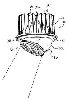
FIGURE 1 is a perspective view of a preferred embodiment of a directionally-
adjustable LED spotlight of the present invention oriented if the embodiment
were
mounted in a ceiling.
FIGURE 2 is a side view of the fixed heat sink of the embodiment of FIGURE
1.

FIGURE 3a is a top view of the fixed heat sink of FIGURE 2.
FIGURE 3b is a side view of the ball portion of the LED-array bearing
structure of FIGURE 1.

FIGURE 4a is a top view of the ball portion of the LED-array-bearing
structure of FIGURE 3b.
FIGURE 4b is a top view of the LED array of the LED-array-bearing structure
of the embodiment of FIGURE 1.

DETAILED DESCRIPTION OF THE PREFERRED EMBODIMENTS
FIGURE 1 illustrates a preferred embodiment of a directionally-adjustable
LED spotlight 10 of the current invention. The LED spotlight 10 includes a
fixed heat
sink 20 and an LED-array-bearing structure 30. As seen in FIGURE 2, the heat
sink
-3-


CA 02602780 2007-09-18

20 is in a socket shape shown in the socket portion 22 and further includes a
plurality
of fins 24 that extend outwardly from an outer surface 26 of the heat sink 20.
Referring again to FIGURE 1, the LED-array-bearing structure 30 includes a
ball portion 32 and an LED array 34. As can be seen in FIGURES 3a and 3b, the
ball
portion 32 is sized to fit inside the socket portion 22 of the heat sink 20.
Furthermore,
the ball portion 32 is made of metal and is hollow. The ball and socket dcsign
of the
heat sink 20 and the LED-array-bearing structure 30 allow for the entirety of
the
socket portion 22 of the heat sink 20 to be in contact with the ball portion
32 of the
LED-array-bearing structure 30. This contact ensures a beat transfer
relationship
between the two parts.
As shown in FIGURE 4a the ball portion 32 is not completely spherical, rather
the ball portion 32 includes platform portion 36 that defines the top of the
ball portion
32. FIGURE 4b shows the LED array 34 that includes a first side 38 having a
plurality of LEDs 40 and second side (not shown). As seen in FIGURES 4a and 4b
the platform portion 36 is sized to receive the LED array 34 wherein the
second side
of the LED 34 array will come in contact with the platform portion 36. This
sizing
arrangement allows for efficient heat transfer from the LED array 34 to the
ball
portion 32 whereby heat can be transferred to the heat sink 20 and the fins
24.
Referring again to FIGURE 1, the LED spotlight 10 further includes a collar
12 for securing the LED-array-bearing structure 30 in place. Once the LED-
array-
bearing structure 30 has been positioned in the heat sink 20 the collar 12
fits over the
LED-array-bearing structure 30 and comes in contact with an upper edge 28 of
the
heat sink 20. The collar 12 is then secured using screws or other means and
the LED-
array-bearing structure 30 is then secured in place. In other embodiments, not
shown,
the collar could be divided into sections rather than one piece. To readjust
the LED-
array-bearing structure 30 the collar 12 must simply be loosed and the LED-
array-
bearing structure 30 can be rotated to a different angle.
While the principles of the invention have been shown and described in
connection with specific embodiments, it is to be understood that such
embodiments
are by way of example and are not limiting.

-4-

Representative Drawing
A single figure which represents the drawing illustrating the invention.
Administrative Status

For a clearer understanding of the status of the application/patent presented on this page, the site Disclaimer , as well as the definitions for Patent , Administrative Status , Maintenance Fee  and Payment History  should be consulted.

Administrative Status

Title Date
Forecasted Issue Date 2014-06-17
(22) Filed 2007-09-18
(41) Open to Public Inspection 2008-03-30
Examination Requested 2011-09-06
(45) Issued 2014-06-17

Abandonment History

There is no abandonment history.

Maintenance Fee

Last Payment of $458.08 was received on 2022-09-09


 Upcoming maintenance fee amounts

Description Date Amount
Next Payment if small entity fee 2023-09-18 $253.00
Next Payment if standard fee 2023-09-18 $624.00

Note : If the full payment has not been received on or before the date indicated, a further fee may be required which may be one of the following

  • the reinstatement fee;
  • the late payment fee; or
  • additional fee to reverse deemed expiry.

Patent fees are adjusted on the 1st of January every year. The amounts above are the current amounts if received by December 31 of the current year.
Please refer to the CIPO Patent Fees web page to see all current fee amounts.

Payment History

Fee Type Anniversary Year Due Date Amount Paid Paid Date
Application Fee $400.00 2007-09-18
Maintenance Fee - Application - New Act 2 2009-09-18 $100.00 2009-09-09
Maintenance Fee - Application - New Act 3 2010-09-20 $100.00 2010-09-10
Request for Examination $800.00 2011-09-06
Maintenance Fee - Application - New Act 4 2011-09-19 $100.00 2011-09-06
Maintenance Fee - Application - New Act 5 2012-09-18 $200.00 2012-09-17
Maintenance Fee - Application - New Act 6 2013-09-18 $200.00 2013-08-22
Registration of a document - section 124 $100.00 2014-03-20
Final Fee $300.00 2014-03-28
Maintenance Fee - Patent - New Act 7 2014-09-18 $200.00 2014-08-22
Maintenance Fee - Patent - New Act 8 2015-09-18 $200.00 2015-08-27
Maintenance Fee - Patent - New Act 9 2016-09-19 $200.00 2016-08-24
Maintenance Fee - Patent - New Act 10 2017-09-18 $250.00 2017-08-23
Maintenance Fee - Patent - New Act 11 2018-09-18 $250.00 2018-08-29
Maintenance Fee - Patent - New Act 12 2019-09-18 $250.00 2019-09-13
Registration of a document - section 124 2019-11-15 $100.00 2019-11-15
Maintenance Fee - Patent - New Act 13 2020-09-18 $250.00 2020-09-11
Maintenance Fee - Patent - New Act 14 2021-09-20 $255.00 2021-09-10
Maintenance Fee - Patent - New Act 15 2022-09-19 $458.08 2022-09-09
Owners on Record

Note: Records showing the ownership history in alphabetical order.

Current Owners on Record
IDEAL INDUSTRIES LIGHTING LLC
Past Owners on Record
CREE, INC.
GUILLIEN, WAYNE
RUUD LIGHTING, INC.
WALCZAK, STEVEN R.
WILCOX, KURT
Past Owners that do not appear in the "Owners on Record" listing will appear in other documentation within the application.
Documents

To view selected files, please enter reCAPTCHA code :


To view images, click a link in the Document Description column. To download the documents, select one or more checkboxes in the first column and then click the "Download Selected in PDF format (Zip Archive)" or the "Download Selected as Single PDF" button.

List of published and non-published patent-specific documents on the CPD .

If you have any difficulty accessing content, you can call the Client Service Centre at 1-866-997-1936 or send them an e-mail at CIPO Client Service Centre.


Document
Description 
Date
(yyyy-mm-dd) 
Number of pages   Size of Image (KB) 
Representative Drawing 2008-03-10 1 8
Abstract 2007-09-18 1 7
Description 2007-09-18 4 163
Claims 2007-09-18 2 47
Drawings 2007-09-18 4 71
Cover Page 2008-03-25 1 32
Drawings 2013-08-07 4 73
Claims 2013-08-07 2 54
Representative Drawing 2014-05-23 1 10
Cover Page 2014-05-23 1 32
Assignment 2007-09-18 3 92
Prosecution-Amendment 2011-09-06 1 42
Prosecution-Amendment 2011-12-07 1 35
Prosecution-Amendment 2013-02-12 2 58
Assignment 2014-03-28 1 49
Prosecution-Amendment 2013-08-07 11 411
Assignment 2014-03-20 5 202
Correspondence 2014-03-28 2 52