Note: Descriptions are shown in the official language in which they were submitted.
CA 02602804 2008-06-16
74769-1840
1
SYSTEMS, METHODS, AND APPARATUS FOR HIGHBAND
BURST SUPPRESSION
FIELD OF THE INVENTION
[0002] This invention relates to signal processing.
BACKGROUND
[0003] Voice communications over the public switched telephone network (PSTN)
have traditionally been limited in bandwidth to the frequency range of 300-
3400 kHz.
New networks for voice communications, such as cellular telephony and voice
over IP
(VolP), may not have the same bandwidth limits, and it may be desirable to
transmit
and receive voice communications that include a wideband frequency range over
such
networks. For example, it may be desirable to support an audio frequency range
that
extends down to 50 Hz and/or up to 7 or 8 kHz. It may also be desirable to
support
other applications, such as high-quality audio or audio/video conferencing,
that may
have audio speech content in ranges outside the traditional PSTN limits.
[0004] Extension of the range supported by a speech coder into higher
frequencies
may improve intelligibility. For example, the information that differentiates
fricatives
such as 's' and `f is largely in the high frequencies. Highband extension may
also
improve other qualities of speech, such as presence. For example, even a
voiced vowel
may have spectral energy far above the PSTN limit.
[0005] In conducting research on wideband speech signals, the inventors have
occasionally observed pulses of high energy, or "bursts", in the upper part of
the
CA 02602804 2008-06-16
74769-1840
2
spectrum. These highband bursts typically last only a few milliseconds
(typically 2
milliseconds, with a maximum length of about 3 milliseconds), may span up to
several
kilohertz (kHz) in frequency, and occur apparently randomly during different
types of
speech sounds, both voiced and unvoiced. For some speakers, a highband burst
may
occur in every sentence, while for other speakers such bursts may not occur at
all.
While these events do not generally occur frequently, they do seem to be
ubiquitous, as
the inventors have found examples of them in wideband speech samples from
several
different databases and from several other sources.
[0006] Ilighband bursts have a wide frequency range but typically only occur
in the
higher band of the spectrum, such as the region from 3.5 to 7 kHz, and not in
the lower
band. For example, FIGURE 1 shows a spectrogram of the word 'can'. In this
widoband speech signal, a highband burst may be seen at 0.1 seconds extending
across a
wide frequency region around 6 kHz (in this figure, darker regions indicate
higher
intensity). It is possible that at least some highband bursts are generated by
an
interaction between the speaker's mouth and the microphone and/or are due to
clicks
emitted by the speaker's mouth during speech.
CA 02602804 2012-08-30
74769-1840
2a
SUMMARY
[0006a] According to a first broad aspect of the present invention,
there is provided a
method of signal processing, said method comprising: calculating a first burst
indication
signal that indicates whether a burst is detected in a low-frequency portion
of a speech signal;
calculating a second burst indication signal that indicates whether a burst is
detected in a high-
frequency portion of the speech signal; generating an attenuation control
signal according to a
relation between the first and second burst indication signals; applying the
attenuation control
signal to the high-frequency portion of the speech signal to generate a
processed high-
frequency signal portion, wherein calculating at least one of the first and
second burst
indication signals comprises: producing a forward smoothed envelope of a
corresponding
portion of the speech signal, the forward smoothed envelope being smoothed in
a positive
time direction; indicating an initial region of a burst in the forward
smoothed envelope;
producing a backward smoothed envelope of the corresponding portion of the
speech signal,
the backward smoothed envelope being smoothed in a negative time direction;
and indicating
a terminal region of a burst in the backward smoothed envelope.
[0006b] According to a second broad aspect of the present invention,
there is provided
a non-transitory data storage medium having machine-executable instructions
that when
executed by a processor cause the processor to perform the method of signal
processing
according to the first broad aspect of the present invention.
10006c1 According to a third broad aspect of the present invention, there
is provided an
apparatus comprising a highband burst suppressor, said highband burst
suppressor
comprising: a first burst detector configured to output a first burst
indication signal indicating
whether a burst is detected in a low-frequency portion of a speech signal; a
second burst
detector configured to output a second burst indication signal indicating
whether a burst is
detected in a high-frequency portion of the speech signal; an attenuation
control signal
generator configured to generate an attenuation control signal according to a
relation between
the first and second burst indication signals; and a gain control element
configured to apply
the attenuation control signal to the high-frequency portion of the signal,
wherein at least one
CA 02602804 2012-08-30
74769-1840
2b
of said first and second burst detectors comprises: a forward smoother
configured to produce a
forward smoothed envelope of a corresponding portion of the speech signal, the
forward
smoothed envelope being smoothed in a positive time direction; a first region
indicator
configured to indicate an initial region of a burst in the forward smoothed
envelope; a
backward smoother configured to produce a backward smoothed envelope of a
corresponding
portion of the speech signal, the backward smoothed envelope being smoothed in
a negative
time direction; and a second region indicator configured to indicate a
terminal region of a
burst in the backward smoothed envelope.
CA 0 2 6 0 2 8 0 4 2 0 1 2 ¨ 0 8 ¨ 3 0
74769-1840
2c
[000'7] A method of signal processing according to one embodiment includes
processing a wideband speech signal to obtain a lowband speech signal and a
highband
speech signal; determining that a burst is present in a region of the highband
speech
signal; and determining that the burst is absent from a corresponding region
of the
lowband speech signal. The method also includes, based on determining that the
burst
is present and on determining that the burst is absent, attenuating the
highband speech
signal over the region.
[0008] An apparatus according to an embodiment includes a first burst detector
configured to detect bursts in the lowband speech signal; a second burst
detector
configured to detect bursts in a corresponding highband speech signal; an
attenuation
control signal calculator configured to calculate an attenuation control
signal according
to a difference between outputs of the first and second burst detectors; and a
gain
CA 02602804 2007-09-28
WO 2006/107834
PCT/US2006/012228
3
control element configured to apply the attenuation control signal to the
highband
speech signal.
BRIEF DESCRIPTION OF THE DRAWINGS
[0009] FIGURE 1 shows a spectrogram of a signal including a highband burst.
[00010] FIGURE 2 shows a spectrogram of a signal in which a highband burst has
been suppressed.
[00011] FIGURE 3 shows a block diagram of an arrangement including a filter
bank
A110 and a highband burst suppressor C200 according to an embodiment.
[00012] FIGURE 4 shows a block diagram of an arrangement including filter bank
A110, highband burst suppressor C200, and a filter bank B120.
[00013] FIGURE 5a shows a block diagram of an implementation A112 of filter
bank
A110.
[00014] FIGURE 5b shows a block diagram of an implementation B122 of filter
bank
B120.
[00015] FIGURE 6a shows bandwidth coverage of the low and high bands for one
example of filter bank A110.
[00016] FIGURE 6b shows bandwidth coverage of the low and high bands for
another
example of filter bank A110.
[00017] FIGURE 6c shows a block diagram of an implementation A114 of filter
bank
A112.
[00018] FIGURE 6d shows a block diagram of an implementation B124 of filter
bank
B122.
[00019] FIGURE 7 shows a block diagram of an arrangement including filter bank
A110, highband burst suppressor C200, and a highband speech encoder A200.
CA 02602804 2007-09-28
WO 2006/107834
PCT/US2006/012228
4
[00020] FIGURE 8 shows a block diagram of an arrangement including filter bank
A110, highband burst suppressor C200, filter bank B120, and a wideband speech
encoder A100.
[00021] FIGURE 9 shows a block diagram of a wideband speech encoder A102 that
includes highband burst suppressor C200.
[00022] FIGURE 10 shows a block diagram of an implementation A104 of wideband
speech encoder A102.
[00023] FIGURE 11 shows a block diagram of an arrangement including wideband
speech encoder A104 and a multiplexer A130.
[00024] FIGURE 12 shows a block diagram of an implementation C202 of highband
burst suppressor C200.
[00025] FIGURE 13 shows a block diagram of an implementation C12 of burst
detector C10.
[00026] FIGURES 14a and 14b show block diagrams of implementations C52-1, C52-
2 of initial region indicator C50-1 and terminal region indicator C50-2,
respectively.
[00027] FIGURE 15 shows a block diagram of an implementation C62 of
coincidence
detector C60.
[00028] FIGURE 16 shows a block diagram of an implementation C22 of
attenuation
control signal generator C20.
[00029] FIGURE 17 shows a block diagram of an implementation C14 of burst
detector C12.
[00030] FIGURE 18 shows a block diagram of an implementation C16 of burst
detector C14.
[00031] FIGURE 19 shows a block diagram of an implementation C18 of burst
detector C16.
[00032] FIGURE 20 shows a block diagram of an implementation C24 of
attenuation
control signal generator C22.
CA 02602804 2007-09-28
WO 2006/107834 PCT/US2006/012228
DETAILED DESCRIPTION
[00033] Unless expressly limited by its context, the term "calculating" is
used herein to
indicate any of its ordinary meanings, such as computing, generating, and
selecting from
a list of values. Where the term "comprising" is used in the present
description and
claims, it does not exclude other elements or operations.
[00034] Highband bursts are quite audible in the original speech signal, but
they do not
contribute to intelligibility, and the quality of the signal may be improved
by
suppressing them. Highband bursts may also be detrimental to encoding of the
highband speech signal, such that efficiency of coding the signal, and
especially of
encoding the temporal envelope, may be improved by suppressing the bursts from
the
highband speech signal.
[00035] Highband bursts may negatively affect high-band coding systems in
several
ways. First, these bursts may cause the energy envelope of the speech signal
over time
to be much less smooth by introducing a sharp peak at the time of the burst.
Unless the
coder models the temporal envelope of the signal with high resolution, which
increases
the amount of information to be sent to the decoder, the energy of the burst
may become
smeared out over time in the decoded signal and cause artifacts. Second,
highband
bursts tend to dominate the spectral envelope as modeled by, for example, a
set of
parameters such as linear prediction filter coefficients. Such modeling is
typically
performed for each frame of the speech signal (about 20 milliseconds).
Consequently,
the frame containing the click may be synthesized according to a spectral
envelope that
is different from the preceding and following frames, which can lead to a
perceptually
objectionable discontinuity.
[00036] Highband bursts may cause another problem for a speech coding system
in
which an excitation signal for the highband synthesis filter is derived from
or otherwise
represents a narrowband residual. In such case, presence of a highband burst
may
complicate coding of the highband speech signal because the highband speech
signal
includes a structure that is absent from the narrowband speech signal.
CA 02602804 2008-06-16
7 4 7 6 9-1 8 4 0
6
[00037] Embodiments include systems, methods, and apparatus configured to
detect
bursts that exist in a highband speech signal, but not in a corresponding
lowband speech
signal, and to reduce a level of the highband speech signal during each of the
bursts.
Potential advantages of such embodiments include avoiding artifacts in the
decoded
signal and/or avoiding a loss of coding efficiency without noticeably
degrading the
quality of the original signal. FIGURE 2 shows a spectrogram of the wideband
signal
shown in FIGURE 1 after suppression of the highband burst according to such a
method.
[00038] FIGURE 3 shows a block diagram of an arrangement including a filter
bank
A110 and a highband burst suppressor C200 according to an embodiment. Filter
bank
A110 is configured to filter wideband speech signal S10 to produce a lowband
speech
signal S20 and a highband speech signal S30. Highband burst suppressor C200 is
configured to output a processed highband speech signal 330a based on highband
speech signal 530, in which bursts that occur in highband speech signal S30
but are
absent from lowband speech signal S20 have been suppressed.
[00039] FIGURE 4 shows a block diagram of the arrangement shown in FIGURE 3
that also includes a filter bank B120. Filter bank B120 is configured to
combine
lowband speech signal S20 and processed highband speech signal S30a to produce
a
processed wideband speech signal SlOa. The quality of processed wideband
speech
signal SlOa may be improved over that of wideband speech signal S10 due to
suppression of highband bursts.
[00040] Filter bank A110 is configured to filter an input signal according to
a split-
band scheme to produce a low-frequency subband and a high-frequency subband.
Depending on the design criteria for the particular application, the output
subbands may
have equal or unequal bandwidths and may be overlapping or nonoverlapping. A
configuration of filter bank A110 that produces more than two subbands is also
possible. For example, such a filter bank may be configured to produce a very-
low-
band signal that includes components in a frequency range below that of
narrowband
signal S20 (such as the range of 50-300 Hz). In such case, wideband speech
encoder A100
(as introduced with reference to FIG. 8 below) may be implemented to encode
this very-low-
band signal separately, and multiplexer A130 (as introduced with reference to
FIG. 11 below)
may be configured to include the encoded very-low-band signal in multiplexed
signal S70
(e.g., as a separable portion).
CA 02602804 2008-06-16
74769-1840
7
[00041] FIGURE 5a shows a block diagram of an implementation A112 of filter
bank
A110 that is configured to produce two subband signals having reduced sampling
rates.
Filter bank A110 is arranged to receive a wideband speech signal S10 having a
high-
frequency (or highband) portion and a low-frequency (or lowband) portion.
Filter bank
A112 includes a lowband processing path configured to receive wideband speech
signal
S10 and to produce lowband speech signal S20, and a highband processing path
configured to receive wideband speech signal S10 and to produce highband
speech
signal S30. Lowpass filter 110 filters wideband speech signal S10 to pass a
selected
low-frequency subband, and highpass filter 130 filters wideband speech signal
S10 to
pass a selected high-frequency subband. Because both subband signals have more
narrow bandwidths than wideband speech signal S10, their sampling rates can be
reduced to some extent without loss of information. Downsampler 120 reduces
the
sampling rate of the lowpass signal according to a desired decimation factor
(e.g., by
removing samples of the signal and/or replacing samples with average values),
and
downsampler 140 likewise reduces the sampling rate of the highpass signal
according to .
another desired decimation factor.
[00042] FIGURE 5b shows a block diagram of a corresponding implementation B122
of filter bank B120. Upsampler 150 increases the sampling rate of lowband
speech signal
S20 (e.g., by zero-stuffing and/or by duplicating samples), and lowpass filter
160 filters
the upsampled signal to pass only a lowband portion (e.g., to prevent
aliasing).
Likewise, upsampler 170 increases the sampling rate of processed highband
signal S30a and
highpass filter 180 filters the upsampled signal to pass only a highband
portion. The
two passband signals are then summed to form wideband speech signal Si Oa. In
some
implementations of an apparatus that includes filter bank B120, filter bank
B120 is
configured to produce a weighted sum of the two passband signals according to
one or
more weights received and/or calculated by the apparatus. A configuration of
filter
bank B120 that combines more than two passband signals is also contemplated.
[00043] Each of the filters 110, 130, 160, 180 may be implemented as a finite-
impulse-
response (FIR) filter or as an infinite-impulse-response (BR) filter. The
frequency
responses of filters 110 and 130 may have symmetric or dissimilarly shaped
transition
regions between stopband and passband. Likewise, the frequency responses of
filters
160 and 180 may have symmetric or dissimilarly shaped transition regions
between
CA 02602804 2007-09-28
WO 2006/107834
PCT/US2006/012228
8
stopband and passband. It may be desirable but is not strictly necessary for
lowpass
filter 110 to have the same response as lowpass filter 160, and for highpass
filter 130 to
have the same response as highpass filter 180. In one example, the two filter
pairs 110,
130 and 160, 180 are quadrature mirror filter (QMF) banks, with filter pair
110, 130
having the same coefficients as filter pair 160, 180.
[00044] In a typical example, lowpass filter 110 has a passband that includes
the
limited PSTN range of 300-3400 Hz (e.g., the band from 0 to 4 kHz). FIGURES 6a
and 6b show relative bandwidths of wideband speech signal S10, lowband speech
signal
S20, and highband speech signal S30 in two different implementational
examples. In
both of these particular examples, wideband speech signal S10 has a sampling
rate of 16
kHz (representing frequency components within the range of 0 to 8 kHz), and
lowband
signal S20 has a sampling rate of 8 kHz (representing frequency components
within the
range of 0 to 4 kHz).
[00045] In the example of FIGURE 6a, there is no significant overlap between
the two
subbands. A highband signal S30 as shown in this example may be obtained using
a
highpass filter 130 with a passband of 4-8 kHz. In such a case, it may be
desirable to
reduce the sampling rate to 8 kHz by downsampling the filtered signal by a
factor of
two. Such an operation, which may be expected to significantly reduce the
computational complexity of further processing operations on the signal, will
move the
passband energy down to the range of 0 to 4 kHz without loss of information.
[00046] In the alternative example of FIGURE 6b, the upper and lower subbands
have
an appreciable overlap, such that the region of 3.5 to 4 kHz is described by
both
subband signals. A highband signal S30 as in this example may be obtained
using a
highpass filter 130 with a passband of 3.5-7 kHz. In such a case, it may be
desirable to
reduce the sampling rate to 7 kHz by downsampling the filtered signal by a
factor of
16/7. Such an operation, which may be expected to significantly reduce the
computational complexity of further processing operations on the signal, will
move the
passband energy down to the range of 0 to 3.5 kHz without loss of information.
[00047] In a typical handset for telephonic communication, one or more of the
transducers (i.e., the microphone and the earpiece or loudspeaker) lacks an
appreciable
response over the frequency range of 7-8 kHz. In the example of FIGURE 6b, the
CA 02602804 2008-06-16
74769-1840
9
portion of wideband speech signal S10 between 7 and 8 kHz is not included in
the
encoded signal. Other particular examples of highpass filter 130 have
passbands of 3.5-
'73 kHz and 3.5-8 kHz.
[00048] In some implementations, providing an overlap between subbands as in
the
example of FIGURE 6b allows for the use of a lowpass and/or a highpass filter
having a
smooth rolloff over the overlapped region. Such filters are typically less
computationally complex and/or introduce less delay than filters with sharper
or "brick-
wall" responses. Filters having sharp transition regions tend to have higher
sidelobes
(which may cause aliasing) than filters of similar order that have smooth
rolloffs.
Filters having sharp transition regions may also have long impulse responses
which may
cause ringing artifacts. For filter bank implementations having one or more DR
filters,
allowing for a smooth rolloff over the overlapped region may enable the use of
a filter
or filters whose poles are farther away from the unit circle, which may be
important to
ensure a stable fixed-point implementation.
[00049] Overlapping of subbands allows a smooth blending of lowband and
highband
that may lead to fewer audible artifacts, reduced aliasing, and/or a less
noticeable
transition from one band to the other. Moreover, in an application where the
lowband
and highband speech signals S20, S30 are subsequently encoded by different
speech
encoders, the coding efficiency of the lowband speech encoder (for example, a
waveform coder) may drop with increasing frequency. For example, coding
quality of
the lowband speech coder may be reduced at low bit rates, especially in the
presence of
background noise. In such cases, providing an overlap of the subbands may
increase the
quality of reproduced frequency components in the overlapped region.
[00050] Moreover, overlapping of subbands allows a smooth blending of lowband
and
highband that may lead to fewer audible artifacts, reduced aliasing, and/or a
less
noticeable transition from one band to the other. Such a feature may be
especially
desirable for an implementation in which lowband speech encoder A120 and
highband speech encoder
A200 as discussed below operate according to different coding methodologies.=
For
example, different coding techniques may produce signals that sound quite
different. A
coder that encodes a spectral envelope in the form of codebook indices may
produce a
signal having a different sound than a coder that encodes the amplitude
spectrum
instead. A time-domain coder (e.g., a pulse-code-modulation or PCM coder) may
=
CA 02602804 2007-09-28
WO 2006/107834 PCT/US2006/012228
produce a signal having a different sound than a frequency-domain coder. A
coder that
encodes a signal with a representation of the spectral envelope and the
corresponding
residual signal may produce a signal having a different sound than a coder
that encodes
a signal with only a representation of the spectral envelope. A coder that
encodes a
signal as a representation of its waveform may produce an output having a
different
sound than that from a sinusoidal coder. In such cases, using filters having
sharp
transition regions to define nonoverlapping subbands may lead to an abrupt and
perceptually noticeable transition between the subbands in the synthesized
wideband
signal.
[00051] Although QMF filter banks having complementary overlapping frequency
responses are often used in subband techniques, such filters are unsuitable
for at least
some of the wideband coding implementations described herein. A QMF filter
bank at
the encoder is configured to create a significant degree of aliasing that is
canceled in the
corresponding QMF filter bank at the decoder. Such an arrangement may not be
appropriate for an application in which the signal incurs a significant amount
of
distortion between the filter banks, as the distortion may reduce the
effectiveness of the
alias cancellation property. For example, applications described herein
include coding
implementations configured to operate at very low bit rates. As a consequence
of the
very low bit rate, the decoded signal is likely to appear significantly
distorted as
compared to the original signal, such that use of QMF filter banks may lead to
uncanceled aliasing. Applications that use QMF filter banks typically have
higher bit
rates (e.g., over 12 kbps for AMR, and 64 kbps for G.722).
[00052] Additionally, a coder may be configured to produce a synthesized
signal that is
perceptually similar to the original signal but which actually differs
significantly from
the original signal. For example, a coder that derives the highband excitation
from the
narrowband residual as described herein may produce such a signal, as the
actual
highband residual may be completely absent from the decoded signal. Use of QMF
filter banks in such applications may lead to a significant degree of
distortion caused by
uncanceled aliasing.
[00053] The amount of distortion caused by QMF aliasing may be reduced if the
affected subband is narrow, as the effect of the aliasing is limited to a
bandwidth equal
to the width of the subband. For examples as described herein in which each
subband
CA 02602804 2007-09-28
WO 2006/107834
PCT/US2006/012228
11
includes about half of the wideband bandwidth, however, distortion caused by
uncanceled aliasing could affect a significant part of the signal. The quality
of the
signal may also be affected by the location of the frequency band over which
the
uncanceled aliasing occurs. For example, distortion created near the center of
a
wideband speech signal (e.g., between 3 and 4 kHz) may be much more
objectionable
than distortion that occurs near an edge of the signal (e.g., above 6 kHz).
[00054] While the responses of the filters of a WY filter bank are strictly
related to
one another, the lowband and highband paths of filter banks A110 and B120 may
be
configured to have spectra that are completely unrelated apart from the
overlapping of
the two subbands. We define the overlap of the two subbands as the distance
from the
point at which the frequency response of the highband filter drops to ¨20 dB
up to the
point at which the frequency response of the lowband filter drops to ¨20 dB.
In various
examples of filter bank A110 and/or B120, this overlap ranges from around 200
Hz to
around 1 kHz. The range of about 400 to about 600 Hz may represent a desirable
tradeoff between coding efficiency and perceptual smoothness. In one
particular
example as mentioned above, the overlap is around 500 Hz.
[00055] It may be desirable to implement filter bank A112 and/or B122 to
perform
operations as illustrated in FIGURES 6a and 6b in several stages. For example,
FIGURE 6c shows a block diagram of an implementation A114 of filter bank A112
that
performs a functional equivalent of highpass filtering and downsampling
operations
using a series of interpolation, resampling, decimation, and other operations.
Such an
implementation may be easier to design and/or may allow reuse of functional
blocks of
logic and/or code. For example, the same functional block may be used to
perform the
operations of decimation to 14 kHz and decimation to 7 kHz as shown in FIGURE
6c.
The spectral reversal operation may be implemented by multiplying the signal
with the
function eft"' or the sequence (-1)fl, whose values alternate between +1 and
¨1. The
spectral shaping operation may be implemented as a lowpass filter configured
to shape
the signal to obtain a desired overall filter response.
[00056] It is noted that as a consequence of the spectral reversal operation,
the
spectrum of highband signal S30 is reversed. Subsequent operations in the
encoder and
corresponding decoder may be configured accordingly. For example, it may be
desired
to produce a corresponding excitation signal that also has a spectrally
reversed form.
CA 02602804 2008-06-16
74769-1840
12
[00057] FIGURE 6d shows a block diagram of an implementation B124 of filter
bank
13122 that performs a functional equivalent of upsampling and highpass
filtering
operations using a series of interpolation, resampling, and other operations.
Filter bank
B124 includes a spectral reversal operation in the highband that reverses a
similar
operation as performed, for example, in a filter bank of the encoder such as
filter bank
A114. In this particular example, filter bank B124 also includes notch filters
in the
lowband and highband that attenuate a component of the signal at 7100 Hz,
although
such filters are optional and need not be included. The Patent Application
"SYSTEMS,
METHODS, AND APPARATUS FOR SPF.FCH SIGNAL FILTERING" filed
herewith, published as U.S. Pub. No. 2007/0088558, includes additional
description
and figures relating to responses of elements of particular implementations of
filter
banks A110 and B120.
[00058] As noted above, highband burst suppression may improve the efficiency
of
coding highband speech signal S30. FIGURE 7 shows a block diagram of an
arrangement in which processed highband speech signal S30a, as produced by
highband
burst suppressor C200, is encoded by a highband speech encoder A200 to produce
encoded highband speech signal S30b.
[00059] One approach to wideband speech coding involves scaling a narrowband
speech coding technique (e.g., one configured to encode the range of 0-4 kHz)
to cover
the wideband spectrum. For example, a speech signal may be sampled at a higher
rate
to include components at high frequencies, and a narrowband coding technique
may be
reconfigured to use more filter coefficients to represent this wideband
signal. FIGURE
8 shows a block diagram of an example in which a wideband speech encoder A100
is
arranged to encode processed wideband speech signal SlOa to produce encoded
wideband speech signal SlOb.
[00060] Narrowband coding techniques such as CELP (codebook excited linear
prediction) are computationally intensive, however, and a wideband CR1 .P
coder may
consume too many processing cycles to be practical for many mobile and other
embedded applications. Encoding the entire spectrum of a wideband signal to a
desired
quality using such a technique may also lead to an unacceptably large increase
in
bandwidth. Moreover, transcoding of such an encoded signal would be required
before
even its narrowband portion could be transmitted into and/or decoded by a
system that
CA 02602804 2008-06-16
7 4 7 6 9-1 8 4 0
13
only supports narrowband coding_ FIGURE 9 shows a block diagram of a wideband
speech encoder A102 that includes separate lowband and highband speech
encoders
A120 and A200, respectively.
[000611 It may be desirable to implement wideband speech coding such that at
least the
narrowband portion of the encoded signal may be sent through a narrowband
channel
(such as a PSTN channel) without transcoding or other significant
modification.
Efficiency of the wideband coding extension may also be desirable, for
example, to
avoid a significant reduction in the number of users that may be serviced in
applications
such as wireless cellular telephony and broadcasting over wired and wireless
channels.
[00062] One approach to wideband speech coding involves extrapolating the
highband
spectral envelope from the encoded narrowband spectral envelope. While such an
approach may be implemented without any increase in bandwidth and without a
need -
for transcoding, however, the coarse spectral envelope or formant structure of
the
highband portion of a speech signal generally cannot be predicted accurately
from the
spectral envelope of the narrowband portion_
[000631 FIGURE 10 shows a block diagram of a wideband speech encoder A104 that
uses another approach to encoding the highband speech signal according to
information -
from the lowband speech signal. In this example, the highband excitation
signal is
derived from the encoded lowband excitation signal S50. Encoder A104 may be
configured to encode a gain envelope based on a signal based on the highband
excitation signal, for example, according to one or more such embodiments as
described in the published patent application WO 2006/107837 entitled METHODS
AND APPARATUS FOR ENCODING AND DECODING AN HIGHBAND PORTION
OF A SPEECH SIGNAL. One particular example of wideband speech encoder A104 is
configured to encode wideband speech signal S10 at a rate of about 8.55 kbps
(kilobits
per second), with about 7.55 kbps being used for lowband filter parameters S40
and
encoded lowband excitation signal S50, and about 1 kbps being used for encoded
highband speech S30b.
[00064] It may be desired to combine the encoded lowband and highband signals
into a
single bitstream. For example, it may be desired to multiplex the encoded
signals
together for transmission (e.g., over a wired, optical, or wireless
transmission channel),
CA 02602804 2008-06-16
74769-1840
14
or for storage, as an encoded wideband speech signal. FIGURE 11 shows a block
diagram of an arrangement including wideband speech encoder A104 and a
multiplexer
A130 configured to combine lowband filter parameters S40, encoded lowband
excitation signal S50, and encoded highband speech signal S30b into a
multiplexed signal S70.
[00065] It may be desirable for multiplexer A130 to be configured to embed the
encoded lowband signal (including lowband filter parameters S40 and encoded
lowband
excitation signal S50) as a separable substream of multiplexed signal S70,
such that the
encoded lowband signal may be recovered and decoded independently of another
portion of multiplexed signal S70 such as a highband and/or very-low-band
signal. For
example, multiplexed signal S70 may be arranged such that the encoded lowband
signal
may be recovered by stripping away the encoded highband speech signal S30b.
One potential
advantage of such a feature is to avoid the need for transcoding the encoded
wideband
signal before passing it to a system that supports decoding of the lowband
signal but
does not support decoding of the highhand portion.
[00066] An apparatus including a lowband, highband, and/or wideband speech
encoder
as described herein may also include circuitry configured to transmit the
encoded signal
into a transmission channel such as a wired, optical, or wireless channel.
Such an
apparatus may also be configured to perform one or more channel encoding
operations
on the signal, such as error correction encoding (e.g., rate-compatible
convolutional
encoding) and/or error detection encoding (e.g., cyclic redundancy encoding),
and/or
one or more layers of network protocol encoding (e.g., Ethernet, TCP/IP,
cdma2000).
[00067] Any or all of the lowband, highband, and wideband speech encoders
described
herein may be implemented according to a source-filter model that encodes the
input
speech signal as (A) a set of parameters that describe a filter and (B) an
excitation signal
that drives the described filter to produce a synthesized reproduction of the
input speech
signal. For example, a spectral envelope of a speech signal is characterized
by a number
of peaks that represent resonances of the vocal tract and are called formants.
Most
speech coders encode at least this coarse spectral structure as a set of
parameters such as
filter coefficients.
[00068] In one example of a basic source-filter arrangement, an analysis
module
calculates a set of parameters that characterize a filter corresponding to the
speech
=
CA 02602804 2007-09-28
WO 2006/107834
PCT/US2006/012228
sound over a period of time (typically 20 msec). A whitening filter (also
called an
analysis or prediction error filter) configured according to those filter
parameters
removes the spectral envelope to spectrally flatten the signal. The resulting
whitened
signal (also called a residual) has less energy and thus less variance and is
easier to
encode than the original speech signal. Errors resulting from coding of the
residual
signal may also be spread more evenly over the spectrum. The filter parameters
and
residual are typically quantized for efficient transmission over the channel.
At the
decoder, a synthesis filter configured according to the filter parameters is
excited by the
residual to produce a synthesized version of the original speech sound. The
synthesis
filter is typically configured to have a transfer function that is the inverse
of the transfer
function of the whitening filter.
[00069] The analysis module may be implemented as a linear prediction coding
(LPC)
analysis module that encodes the spectral envelope of the speech signal as a
set of linear
prediction (LP) coefficients (e.g., coefficients of an all-pole filter
1/A(z)). The analysis
module typically processes the input signal as a series of nonoverlapping
frames, with a
new set of coefficients being calculated for each frame. The frame period is
generally a
period over which the signal may be expected to be locally stationary; one
common
example is 20 milliseconds (equivalent to 160 samples at a sampling rate of 8
kHz).
One example of a lowband LPC analysis module is configured to calculate a set
of ten
LP filter coefficients to characterize the formant structure of each 20-
millisecond frame
of lowband speech signal S20, and one example of a highband LPC analysis
module is
configured to calculate a set of six (alternatively, eight) LP filter
coefficients to
characterize the formant structure of each 20-millisecond frame of highband
speech
signal S30. It is also possible to implement the analysis module to process
the input
signal as a series of overlapping frames.
[00070] The analysis module may be configured to analyze the samples of each
frame
directly, or the samples may be weighted first according to a windowing
function (for
example, a Hamming window). The analysis may also be performed over a window
that is larger than the frame, such as a 30-msec window. This window may be
symmetric (e.g. 5-20-5, such that it includes the 5 milliseconds immediately
before and
after the 20-millisecond frame) or asymmetric (e.g. 10-20, such that it
includes the last
10 milliseconds of the preceding frame). An LPC analysis module is typically
CA 02602804 2007-09-28
WO 2006/107834 PCT/US2006/012228
16
configured to calculate the LP filter coefficients using a Levinson-Durbin
recursion or
the Leroux-Gueguen algorithm. In another implementation, the analysis module
may be
configured to calculate a set of cepstral coefficients for each frame instead
of a set of LP
filter coefficients.
[00071] The output rate of a speech encoder may be reduced significantly, with
relatively little effect on reproduction quality, by quantizing the filter
parameters.
Linear prediction filter coefficients are difficult to quantize efficiently
and are usually
mapped by the speech encoder into another representation, such as line
spectral pairs
(LSPs) or line spectral frequencies (LSFs), for quantization and/or entropy
encoding.
Other one-to-one representations of LP filter coefficients include parcor
coefficients;
log-area-ratio values; immittance spectral pairs (ISPs); and immittance
spectral
frequencies (ISFs), which are used in the GSM (Global System for Mobile
Communications) AMR-WB (Adaptive Multirate-Wideband) codec. Typically a
transform between a set of LP filter coefficients and a corresponding set of
LSFs is
reversible, but embodiments also include implementations of a speech encoder
in which
the transform is not reversible without error.
[00072] A speech encoder is typically configured to quantize the set of
narrowband
LSFs (or other coefficient representation) and to output the result of this
quantization as
the filter parameters. Quantization is typically performed using a vector
quantizer that
encodes the input vector as an index to a corresponding vector entry in a
table or
codebook. Such a quantizer may also be configured to perform classified vector
quantization. For example, such a quantizer may be configured to select one of
a set of
codebooks based on information that has already been coded within the same
frame
(e.g., in the lowband channel and/or in the highband channel). Such a
technique
typically provides increased coding efficiency at the expense of additional
codebook
storage.
[00073] A speech encoder may also be configured to generate a residual signal
by
passing the speech signal through a whitening filter (also called an analysis
or prediction
error filter) that is configured according to the set of filter coefficients.
The whitening
filter is typically implemented as a FIR filter, although IIR implementations
may also be
used. This residual signal will typically contain perceptually important
information of
the speech frame, such as long-term structure relating to pitch, that is not
represented in
CA 02602804 2008-06-16
74769-1840
17
the filter parameters. Again, this residual signal is typically quantized for
output. For
example, lowband speech encoder A122 may be configured to calculate a
quantized
representation of the residual signal for output as encoded lowband excitation
signal
S50. Such quantization is typically performed using a vector quantizer that
encodes the
input vector as an index to a corresponding vector entry in a table or
codebook and that
may be configured to perform classified vector quantization as described
above.
[000741 Alternatively, such a quantizer may be configured to send one or more
parameters from which the vector may be generated dynamically at the decoder,
rather
than retrieved from storage, as in a sparse codebook method. Such a method is
used in
coding schemes such as algebraic CELP (codebook excitation linear prediction)
and
codecs such as 3GPP2 (Third Generation Partnership 2) EVRC (Enhanced Variable
Rate Codec).
[00075] Some implementations of lowband speech encoder A120 are configured to
calculate encoded lowband excitation signal S50 by identifying one among a set
of
codebook vectors that best matches the residual signal. It is noted, however,
that
lowband speech encoder A120 may also be implemented to calculate a quantized
representation of the residual signal without actually generating the residual
signal. For
example, lowband speech encoder A120 may be configured to use a number of
codebook
vectors to generate corresponding synthesized signals (e.g., according to a
current set of
filter parameters), and to select the codebook vector associated with the
generated signal
that best matches the original lowband speech signal S20 in a perceptually
weighted
domain.
[00076] It may be desirable to implement lowband speech encoder A120 or A122
as an
analysis-by-synthesis speech encoder. Codebook excitation linear prediction
(CELP)
coding is one popular family of analysis-by-synthesis coding, and
implementations of
such coders may perform waveform, encoding of the residual, including such
operations
as selection of entries from fixed and adaptive codeboolcs, error minimization
operations, and/or perceptual weighting operations. Other implementations of
analysis-
by-synthesis coding include mixed excitation linear prediction (MELP),
algebraic CFI P
(ACELP), relaxation CELP (RCELP), regular pulse excitation (RPE), multi-pulse
CELP
(WE), and vector-sum excited linear prediction (VSFIP) coding. Related coding
methods include multi-band excitation (MBE) and prototype waveform
interpolation
CA 02602804 2007-09-28
WO 2006/107834 PCT/US2006/012228
18
(PWI) coding. Examples of standardized analysis-by-synthesis speech codecs
include
the ETSI (European Telecommunications Standards Institute)-GSM full rate codec
(GSM 06.10), which uses residual excited linear prediction (RELP); the GSM
enhanced
full rate codec (ETSI-GSM 06.60); the ITU (International Telecommunication
Union)
standard 11.8 kb/s G.729 Annex E coder; the IS (Interim Standard)-641 codecs
for IS-
136 (a time-division multiple access scheme); the GSM adaptive multirate (GSM-
AMR)
codecs; and the 4GVTM (Fourth-Generation VocoderTM) codec (QUALCOMM
Incorporated, San Diego, CA). Existing implementations of RCELP coders include
the
Enhanced Variable Rate Codec (EVRC), as described in Telecommunications
Industry
Association (TIA) IS-127, and the Third Generation Partnership Project 2
(3GPP2)
Selectable Mode Vocoder (SMV). The various lowband, highband, and wideband
encoders described herein may be implemented according to any of these
technologies,
or any other speech coding technology (whether known or to be developed) that
represents a speech signal as (A) a set of parameters that describe a filter
and (B) a
residual signal that provides at least part of an excitation used to drive the
described
filter to reproduce the speech signal.
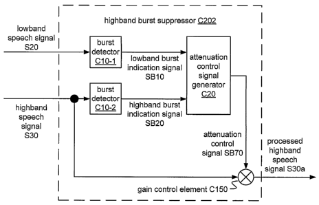
[00077] FIGURE 12 shows a block diagram of an implementation C202 of highband
burst suppressor C200 that includes two implementations C10-1, C10-2 of burst
detector C10. Burst detector C10-1 is configured to produce a lowband burst
indication
signal SB10 that indicates a presence of a burst in lowband speech signal S20.
Burst
detector C10-2 is configured to produce a highband burst indication signal
SB20 that
indicates a presence of a burst in highband speech signal S30. Burst detectors
C10-1
and C10-2 may be identical or may be instances of different implementations of
burst
detector C10. Highband burst suppressor C202 also includes an attenuation
control
signal generator C20 configured to generate an attenuation control signal SB70
according to a relation between lowband burst indication signal SB10 and
highband
burst indication signal SB20, and a gain control element C150 (e.g., a
multiplier or
amplifier) configured to apply attenuation control signal SB70 to highband
speech
signal S30 to produce processed highband speech signal S30a.
[00078] In the particular examples described herein, it may be assumed that
highband
burst suppressor C202 processes highband speech signal S30 in 20-millisecond
frames,
and that lowband speech signal S20 and highband speech signal S30 are both
sampled at
CA 02602804 2007-09-28
WO 2006/107834
PCT/US2006/012228
19
8 kHz. However, these particular values are examples only, and not
limitations, and
other values may also be used according to particular design choices and/or as
noted
herein.
[00079] Burst detector C10 is configured to calculate forward and backward
smoothed
envelopes of the speech signal and to indicate the presence of a burst
according to a
time relation between an edge in the forward smoothed envelope and an edge in
the
backward smoothed envelope. Burst suppressor C202 includes two instances of
burst
detector C10, each arranged to receive a respective one of speech signals S20,
S30 and
to output a corresponding burst indication signal SB10, SB20.
[00080] FIGURE 13 shows a block diagram of an implementation C12 of burst
detector C10 that is arranged to receive one of speech signals S20, S30 and to
output a
corresponding burst indication signal SB10, SB20. Burst detector C12 is
configured to
calculate each of the forward and backward smoothed envelopes in two stages.
In the
first stage, a calculator C30 is configured to convert the speech signal to a
constant-
polarity signal. In one example, calculator C30 is configured to compute the
constant-
polarity signal as the square of each sample of the current frame of the
corresponding
speech signal. Such a signal may be smoothed to obtain an energy envelope. In
another
example, calculator C30 is configured to compute the absolute value of each
incoming
sample. Such a signal may be smoothed to obtain an amplitude envelope. Further
implementations of calculator C30 may be configured to compute the constant-
polarity
signal according to another function such as clipping.
[00081] In the second stage, a forward smoother C40-1 is configured to smooth
the
constant-polarity signal in a forward time direction to produce a forward
smoothed
envelope, and a backward smoother C40-2 is configured to smooth the constant-
polarity
signal in a backward time direction to produce a backward smoothed envelope.
The
forward smoothed envelope indicates a difference in the level of the
corresponding
speech signal over time in the forward direction, and the backward smoothed
envelope
indicates a difference in the level of the corresponding speech signal over
time in the
backward direction.
CA 02602804 2012-08-30
74769-1840
[00082] In one example, forward smoother C40-1 is implemented as a first-order
infinite-impulse-response (Mt) filter configured to smooth the constant-
polarity signal
according to an expression such as the following:
Sf (n) = aSf (n-1) + (1¨ a)P(n),
and backward smoother C40-2 is implemented as a first-order IIR filter
configured to
smooth the constant-polarity signal according to an expression such as the
following:
S b() aS b (11 + +(la)P(n) ,
where n is a time index, P(n) is the constant-polarity signal, Sf (n) is the
forward
smoothed envelope, S b (n) is the backward smoothed envelope, and a is a decay
factor
having a value between 0 (no smoothing) and I. It may be noted that due in
part to
operations such as calculation of a backward smoothed envelope, a delay of at
least one
frame may be incurred in processed highband speech signal S30a. However, such
a
delay is relatively unimportant perceptually and is not uncommon even in real-
time
speech processing operations.
[00083] It may be desirable to select a value for a such that the decay time
of the
smoother is similar to the expected duration of a highband burst.
Typically forward smoother C40-1 and backward smoother C40-2 are
configured to perform complementary versions of the same smoothing operation,
and to
use the same value of a , but in some implementations the two smoothers may be
configured to perform different operations and/or to use different values.
Other
recursive or non-recursive smoothing functions, including finite-impulse-
response (FIR)
or 111( filters of higher order, may also be used.
[00084] In other implementations of burst detector C12, one or both of forward
smoother C40-1 and backward smoother C40-2 are configured to perform an
adaptive
smoothing operation. For example, forward smoother C40-1 may be configured to
perform an adaptive smoothing operation according to an expression such as the
following:
CA 02602804 2007-09-28
WO 2006/107834
PCT/US2006/012228
21
P(n), if P(n)f(n ¨1)
S
f(fl) ={
aS f (n ¨1) + (1¨ a)P(n), if P(n) < S f (n
in which smoothing is reduced or, as in this case, disabled at strong leading
edges of the
constant-polarity signal. In this or another implementation of burst detector
C12,
backward smoother C40-2 may be configured to perform an adaptive smoothing
operation according to an expression such as the following:
P(n), if P(n) S b (n +1)
S b (n) =
OeS b (n + 1) + (1¨ a)P(n), if P(n) < S b(n+1)'
in which smoothing is reduced or, as in this case, disabled at strong trailing
edges of the
constant-polarity signal. Such adaptive smoothing may help to define the
beginnings of
burst events in the forward smoothed envelope and the ends of burst events in
the
backward smoothed envelope.
[00085] Burst detector C12 includes an instance of a region indicator C50
(initial
region indicator C50-1) that is configured to indicate the beginning of a high-
level event
(e.g., a burst) in the forward smoothed envelope. Burst detector C12 also
includes an
instance of region indicator C50 (terminal region indicator C50-2) that is
configured to
indicate the ending of a high-level event (e.g., a burst) in the backward
smoothed
envelope.
[00086] FIGURE 14a shows a block diagram of an implementation C52-1 of initial
region indicator C50-1 that includes a delay element C70-1 and an adder. Delay
C70-1
is configured to apply a delay having a positive magnitude, such that the
forward
smoothed envelope is reduced by a delayed version of itself. In another
example, the
current sample or the delayed sample may be weighted according to a desired
weighting
factor.
[00087] FIGURE 14b shows a block diagram of an implementation C52-2 of
terminal
region indicator C50-2 that includes a delay element C70-2 and an adder. Delay
C70-2
is configured to apply a delay having a negative magnitude, such that the
backward
smoothed envelope is reduced by an advanced version of itself. In another
example, the
current sample or the advanced sample may be weighted according to a desired
weighting factor.
CA 02602804 2007-09-28
WO 2006/107834 PCT/US2006/012228
22
[00088] Various delay values may be used in different implementations of
region
indicator C52, and delay values having different magnitudes may be used in
initial
region indicator C52-1 and terminal region indicator C52-2. The magnitude of
the
delay may be selected according to a desired width of the detected region. For
example,
small delay values may be used to perform detection of a narrow edge region.
To obtain
strong edge detection, it may be desired to use a delay having a magnitude
similar to the
expected edge width (for example, about 3 or 5 samples).
[00089] Alternatively, a region indicator C50 may be configured to indicate a
wider
region that extends beyond the corresponding edge. For example, it may be
desirable
for initial region indicator C50-1 to indicate an initial region of an event
that extends in
the forward direction for some time after the leading edge. Likewise, it may
be
desirable for terminal region indicator C50-2 to indicate a teiminal region of
an event
that extends in the backward direction for some time before the trailing edge.
In such
case, it may be desirable to use a delay value having a larger magnitude, such
as a
magnitude similar to that of the expected length of a burst. In one such
example, a
delay of about 4 milliseconds is used.
[00090] Processing by a region indicator C50 may extend beyond the boundaries
of the
current frame of the speech signal, according to the magnitude and direction
of the
delay. For example, processing by initial region indicator C50-1 may extend
into the
preceding frame, and processing by terminal region indicator C50-2 may extend
into the
following frame.
[00091] As compared to other high-level events that may occur in the speech
signal, a
burst is distinguished by an initial region, as indicated in initial region
indication signal
SB50, that coincides in time with a terminal region, as indicated in terminal
region
indication signal SB60. For example, a burst may be indicated when the time
distance
between the initial and terminal regions is not greater than (alternatively,
is less than) a
predetermined coincidence interval, such as the expected duration of a burst.
Coincidence detector C60 is configured to indicate detection of a burst
according to a
coincidence in time of initial and terminal regions in the region indication
signals SB50
and SB60. For an implementation in which initial and terminal region
indication signals
SB50, SB60 indicate regions that extend from the respective leading and
trailing edges,
CA 02602804 2012-08-30
74769-1840
23
for example, coincidence detector C60 may be configured to indicate an overlap
in time
of the extended regions.
[00092] FIGURE 15 shows a block diagram of an implementation C62 of
coincidence
detector C60 that includes a first instance C80-1 of clipper C80 configured to
clip initial
region indication signal SB50, a second instance C80-2 of clipper C80
configured to
clip terminal region indication signal SB60, and a mean calculator C90
configured to
output a corresponding burst indication signal according to a mean of the
clipped
signals. Clipper C80 is configured to clip values of the input signal
according to an
expression such as the following:
out = max(in,0).
[000931 Alternatively, clipper C80 may be configured to threshold the input
signal
according to an expression such as the following:
in, in
out =c
0,0, hz < TL,
where threshold 71. has a value greater than zero. Typically the instances C80-
1 and
C80-2 of clipper C80 will use the same threshold value, but it is possible for
the
two instances C80-1 and C80-2 to use different threshold values.
[00094] Mean calculator C90 is configured to output a corresponding burst
indication
signal SBIO, SB20, according to a mean of the clipped signals, that indicates
the time
location and strength of bursts in the input signal and has a value equal to
or larger than
zero. The geometric mean may provide better results than the arithmetic mean,
especially for distinguishing bursts with defined initial and terminal regions
from other
events that have only a strong initial or terminal region. For example, the
arithmetic
mean of an event with only one strong edge may still be high, whereas the =
geometric mean of an event lacking one of the edges will be low or zero.
However, the
geometric mean is typically more computationally intensive than the arithmetic
mean.
In one example, an instance of mean calculator C90 arranged to process lowband
results
uses the arithmetic mean (i(a+ b)), and an instance of mean calculator C90
arranged to
process highband results uses the more conservative geometric mean (4-a-T).
CA 02602804 2008-06-16
74769-1840
24
[00095] Other implementations of mean calculator C90 may be configured to use
a
different kind of mean, such as the harmonic mean. In a further implementation
of
coincidence detector C62, one or both of the initial and terminal region
indication
signals SB50, SB60 is weighted with respect to the other before or after
clipping.
[00096] Other implementations of coincidence detector C60 are configured to
detect
bursts by measuring a time distance between leading and trailing edges. For
example,
one such implementation is configured to identify a burst as the region
between a
leading edge in initial region indication signal SB50 and a trailing edge in
terminal
region indication signal SB60 that are no more than a predetermined width
apart. The
predetermined width is based on an expected duration of a highband burst, and
in one
example a width of about 4 milliseconds is used.
[00097] A further implementation of coincidence detector C60 is configured to
expand
each leading edge in initial region indication signal SB50 in the forward
direction by a
desired time period (e.g. based on an expected duration of a highband burst),
and to expand
each trailing edge in terminal region indication signal SB60 in the backward
direction
by a desired time period (e.g. based on an expected duration of a highband
burst). Such
an implementation may be configured to generate the corresponding burst
indication
signal SB10, SB20 as the logical AND of these two expanded signals or,
alternatively,
to generate the corresponding burst indication signal SB10, SB20 to indicate a
relative
strength of the burst across an area where the regions overlap (e.g. by
calculating a
mean of the expanded signals). Such an implementation may be configured to
expand only edges that exceed a threshold value. In one example, the edges are
expanded by a time period of about 4 milliseconds.
[00098] Attenuation control signal generator C20 is configured to generate
attenuation
control signal SB70 according to a relation between lowband burst indication
signal
SB10 and highband burst indication signal SB20. For example, attenuation
control
signal generator C20 may be configured to generate attenuation control signal
SB70
according to an arithmetic relation between burst indication signals SB10 and
SB20,
such as a difference.
[00099] FIGURE 16 shows a block diagram of an implementation C22 of
attenuation
control signal generator C20 that is configured to combine lowband burst
indication
CA 02602804 2007-09-28
WO 2006/107834
PCT/US2006/012228
signal SB10 and highband burst indication signal SB20 by subtracting the
former from
the latter. The resulting difference signal indicates where bursts exist in
the high band
that do not occur (or are weaker) in the low band. In a further
implementation, one or
both of the lowband and highband burst indication signals SB10, SB20 is
weighted with
respect to the other.
[000100] Attenuation control signal calculator C100 outputs attenuation
control signal
SB70 according to a value of the difference signal. For example, attenuation
control
signal calculator C100 may be configured to indicate an attenuation that
varies
according to the degree to which the difference signal exceeds a threshold
value.
[000101]It may be desired for attenuation control signal generator C20 to be
configured
to perform operations on logarithmically scaled values. For example, it may be
desirable to attenuate highband speech signal S30 according to a ratio between
the
levels of the burst indication signals (for example, according to a value in
decibels or
dB), and such a ratio may be easily calculated as the difference of
logarithmically scaled
values. The logarithmic scaling warps the signal along the magnitude axis but
does not
otherwise change its shape. FIGURE 17 shows an implementation C14 of burst
detector C12 that includes an instance C130-1, C130-2 of logarithm calculator
C130
configured to logarithmically scale (e.g., according to a base of 10) the
smoothed
envelope in each of the forward and backward processing paths.
[000102]In one example, attenuation control signal calculator C100 is
configured to
calculate values of attenuation control signal SB70 in dB according to the
following
formula:
0, D dB < TdB
[000103] AdB = 201-2 ___________ 7 if D dB > TdB,
1+ exP(D as /1 )
[000104] where D dB denotes the difference between highband burst indication
signal
SB20 and lowband burst indication signal SB10, TdB denotes a threshold value,
and
AdB is the corresponding value of attenuation control signal SB70. In one
particular
example, threshold TdB has a value of 8 dB.
CA 02602804 2008-06-16
74769-1840
26
[000105]In another implementation, attenuation control signal calculator C100
is configured to
indicate a linear attenuation according to the degree to which the difference
signal
exceeds a threshold value (e.g., 3 dB or 4 dB). In this example, attenuation
control
signal Sl370 indicates no attenuation until the difference signal exceeds the
threshold
value. When the difference signal exceeds the threshold value, attenuation
control
signal SB70 indicates an attenuation value that is linearly proportional to
the amount by
which the threshold value is currently exceeded.
[000106]Highband burst suppressor C202 includes a gain control element C150,
such as a
multiplier or amplifier, that is configured to attenuate highband speech
signal S30
according to the current value of attenuation control signal SB70 to produce
processed
highband speech signal S30a. Typically, attenuation control signal SB70
indicates a
value of no attenuation (e.g., a gain of 1.0 or 0 dB) unless a highband burst
has been
detected at the current location of highband speech signal S30, in which case
a typical
attenuation value is a gain reduction of 0.3 or about 10 dB.
[0001071An alternative implementation of attenuation control signal generator
C22 may
be configured to combine lowband burst indication signal SB10 and highband
burst
indication signal SB20 according to a logical relation. In one such example,
the burst
indication signals are combined by computing the logical AND of highband burst
indication signal SB20 and the logical inverse of lowband burst indication
signal SB10.
In this case, each of the burst indication signals may first be thresholded to
obtain a
binary-valued signal, and attenuation control signal calculator C100 may be
configured
to indicate a corresponding one of two attenuation states (e.g., one state
indicating no
attenuation) according to the state of the combined signal.
[000108]Before performing the envelope calculation, it may be desirable to
shape the
spectrum of one or both of speech signals 520 and S30 in order to flatten the
spectrum
and/or to emphasize or attenuate one or more particular frequency regions.
Lowband
speech signal S20, for example, may tend to have more energy at low
frequencies, and it
may be desirable to reduce this energy. It may also be desirable to reduce
high-
frequency components of lowband speech signal S20 such that the burst
detection is
based primarily on the middle frequencies. Spectral shaping is an optional
operation
that may improve the performance of burst suppressor C200.
=
CA 02602804 2008-06-16
74769-1840
27
[000109]FIGURE 18 shows a block diagram of an implementation C16 of burst
detector C14 that includes a shaping filter C110. In one example, filter C110
is
configured to filter lowband speech signal S20 according to a passband
transfer function
such as the following:
1+0.96z-' +0.96C2 +
FIB (Z)
1-0.5z'
which attenuates very low and high frequencies.
[000110]It may be desired to attenuate low frequencies of highband speech
signal S30
and/or to boost higher frequencies. In one example, filter C110 is configured
to filter
highband speech signal S30 according to a highpass transfer function such as
the
following:
0.5+z' +0.5z-2
= FRB (z) +0.5z4 + 0.3z-2
which attenuates frequencies around 4 kHz.
[0001111It may be unnecessary in a practical sense to perform at least some of
the burst
detection operations at the full sampling rate of the corresponding speech
signal S20,
S30. FIGURE 19 shows a block diagram of an implementation c18 of burst
detector
C16 that includes an instance C120-1 of a downsampler C120 that is configured
to
downsample the smoothed envelope in the forward processing path and an
instance
C120-2 of downsampler C120 that is configured to downsample the smoothed
envelope in the backward processing path. In one example, each instance of
downsampler C120 is configured to downsample the envelope by a factor
of eight. For the particular example of a 20-millisecond frame sampled at 8
kHz (160
samples), such a downsampler reduces the envelope to a 1 kHz sampling rate,
of20
samples per frame. Downsampling may considerably reduce the computational
complexity of a highband burst suppression operation without significantly
affecting
performance.
[000112] It may be desirable for the attenuation control signal applied by
gain control
element C150 to have the same sampling rate as highband speech signal S30.
FIGURE
20 shows a block diagram of an implementation C24 of attenuation control
signal
generator C22 that may be used in conjunction with a downsampling version of
burst
detector C10. Attenuation control signal generator C24 includes an upsampler
C140
CA 02602804 2007-09-28
WO 2006/107834
PCT/US2006/012228
28
configured to upsample attenuation control signal SB70 to a signal SB70a
having a
sampling rate equal to that of highband speech signal S30.
[000113] In one example, upsampler C140 is configured to perform the
upsampling by
zeroth-order interpolation of attenuation control signal SB70. In another
example,
upsampler C140 is configured to perform the upsampling by otherwise
interpolating
between the values of attenuation control signal SB70 (e.g., by passing
attenuation
control signal SB70 through an FIR filter) to obtain less abrupt transitions.
In a further
example, upsampler C140 is configured to perform the upsampling using windowed
sine functions.
[000114] In some cases, such as in a battery-powered device (e.g., a cellular
telephone),
highband burst suppressor C200 may be configured to be selectively disabled.
For
example, it may be desired to disable an operation such as highband burst
suppression
in a power-saving mode of the device.
[000115] As mentioned above, embodiments as described herein include
implementations that may be used to perform embedded coding, supporting
compatibility with narrowband systems and avoiding a need for transcoding.
Support
for highband coding may also serve to differentiate on a cost basis between
chips,
chipsets, devices, and/or networks having wideband support with backward
compatibility, and those having narrowband support only. Support for highband
coding
as described herein may also be used in conjunction with a technique for
supporting
lowband coding, and a system, method, or apparatus according to such an
embodiment
may support coding of frequency components from, for example, about 50 or 100
Hz up
to about 7 or 8 kHz.
[000116] As mentioned above, adding highband support to a speech coder may
improve
intelligibility, especially regarding differentiation of fricatives. Although
such
differentiation may usually be derived by a human listener from the particular
context,
highband support may serve as an enabling feature in speech recognition and
other
machine interpretation applications, such as systems for automated voice menu
navigation and/or automatic call processing. Highband burst suppression may
increase
accuracy in a machine interpretation application, and it is contemplated that
an
CA 02602804 2008-06-16
4 7 6 9 - 1 8 4 0
29
implementation of highband burst suppressor C200 may be used in one or more
such
applications without or without speech encoding.
[000117] An apparatus according to an embodiment may be embedded into a
portable
device for wireless communications such as a cellular telephone or personal
digital
assistant (PDA). Alternatively, such an apparatus may be included in another
communications device such as a VolP handset, a personal computer configured
to
support Volt) communications, or a network device configured to route
telephonic or
VolP communications. For example, an apparatus according to an embodiment may
be
implemented in a chip or chipset for a communications device. Depending upon
the
particular application, such a device may also include such features as analog-
to-digital
and/or digital-to-analog conversion of a speech signal, circuitry for
performing
amplification and/or other signal processing operations on a speech signal,
and/or radio-
frequency circuitry for transmission and/or reception of the coded speech
signal.
[000118] It is explicitly contemplated and disclosed that embodiments may
include
and/or be used with any one or more of the other features disclosed in the
published patent applications cited herein. Such features include
generation of a highband excitation signal from a lowband excitation signal,
which may
include other features such as anti-sparseness filtering, harmonic extension
using a
nonlinear function, mixing of a modulated noise signal with a spectrally
extended
signal, and/or adaptive whitening. Such features include time-warping a
highband
speech signal according to a regularization performed in a lowband encoder.
Such
features include encoding of a gain envelope according to a relation between
an original
speech signal and a synthesized speech signal. Such features include use of
overlapping
filter banks to obtain lowband and highband speech signals from a wideband
speech
signal. Such features include shifting of highband signal S30 and/or
a highband excitation signal according to a regularization or other shift of
lowband
excitation signal S50. Such features include fixed or
adaptive smoothing of coefficient representations such as highband LSFs. Such
features
include fixed or adaptive shaping of noise associated with quantization of
coefficient
representations such as LSFs. Such features also include fixed or adaptive
smoothing of
a gain envelope, and adaptive attenuation of a gain envelope.
CA 02602804 2007-09-28
WO 2006/107834 PCT/US2006/012228
[000119]The foregoing presentation of the described embodiments is provided to
enable any person skilled in the art to make or use the present invention.
Various
modifications to these embodiments are possible, and the generic principles
presented
herein may be applied to other embodiments as well. For example, an embodiment
may
be implemented in part or in whole as a hard-wired circuit, as a circuit
configuration
fabricated into an application-specific integrated circuit, or as a firmware
program
loaded into non-volatile storage or a software program loaded from or into a
data
storage medium as machine-readable code, such code being instructions
executable by
an array of logic elements such as a microprocessor or other digital signal
processing
unit. The data storage medium may be an array of storage elements such as
semiconductor memory (which may include without limitation dynamic or static
RAM
(random-access memory), ROM (read-only memory), and/or flash RAM), or
ferroelectric, magnetoresistive, ovonic, polymeric, or phase-change memory; or
a disk
medium such as a magnetic or optical disk. The term "software" should be
understood
to include source code, assembly language code, machine code, binary code,
firmware,
macrocode, microcode, any one or more sets or sequences of instructions
executable by
an array of logic elements, and any combination of such examples.
[000120]The various elements of implementations of highband speech encoder
A200;
wideband speech encoder A100, A102, and A104; and highband burst suppressor
C200;
and arrangements including one or more such apparatus, may be implemented as
electronic and/or optical devices residing, for example, on the same chip or
among two
or more chips in a chipset, although other arrangements without such
limitation are also
contemplated. One or more elements of such an apparatus may be implemented in
whole or in part as one or more sets of instructions arranged to execute on
one or more
fixed or programmable arrays of logic elements (e.g., transistors, gates) such
as
microprocessors, embedded processors, IP cores, digital signal processors,
FPGAs
(field-programmable gate arrays), ASSPs (application-specific standard
products), and
ASICs (application-specific integrated circuits). It is also possible for one
or more such
elements to have structure in common (e.g., a processor used to execute
portions of code
corresponding to different elements at different times, a set of instructions
executed to
perform tasks corresponding to different elements at different times, or an
arrangement
of electronic and/or optical devices performing operations for different
elements at
different times). Moreover, it is possible for one or more such elements to be
used to
CA 02602804 2007-09-28
WO 2006/107834 PCT/US2006/012228
31
perform tasks or execute other sets of instructions that are not directly
related to an
operation of the apparatus, such as a task relating to another operation of a
device or
system in which the apparatus is embedded.
[000121]Embodiments also include additional methods of speech processing,
speech
encoding, and highband burst suppression as are expressly disclosed herein,
e.g., by
descriptions of structural embodiments configured to perform such methods.
Each of
these methods may also be tangibly embodied (for example, in one or more data
storage
media as listed above) as one or more sets of instructions readable and/or
executable by
a machine including an array of logic elements (e.g., a processor,
microprocessor,
microcontroller, or other finite state machine). Thus, the present invention
is not
intended to be limited to the embodiments shown above but rather is to be
accorded the
widest scope consistent with the principles and novel features disclosed in
any fashion
herein.