Note: Descriptions are shown in the official language in which they were submitted.
CA 02603064 2007-09-28
WO 2005/109544 PCT/CA2005/000673
RETAINING APPARATUS FOR ELECTROCHEMICAL GENERATOR
Field of the invention
The present invention relates to polymer batteries made from a plurality of
laminated electrochemical cells and, more specifically, to a retaining
apparatus
adapted to maintain a stack of electrochemical cells under a state of
compression
in order to ensure optimal electrochemical performance.
Background
Laminated electrochemical cells are typically arranged in a stack
configuration
and interconnected to form larger power producing devices, such as modules
or batteries. A grouping of electrochemical cells may be selectively
interconnected in a parallel and/or series relationship to achieve a desired
voltage and current rating.
It has been determined that the performance and service-life of such modules
or batteries are significantly improved by maintaining the layers of the
stacked
electrochemical cells in a state of compression. Improved cell performance may
be realized by maintaining pressure on the two larger opposing surfaces of the
cells during cell cycling. The thermal conduction characteristics of a stack
of
electrochemical cells are significantly improved when forced contact between
adjacent cells is maintained. It is considered desirable that the compressive
forces be distributed uniformly over the surface of application.
One factor that complicates the effective thermal and electrical conduction
for
thin-film electrochemical cells in a stack configuration is the cyclical
changes in
cell volume that occur during charge and discharge cycles. The volume of an
electrochemical cell varies during charge and discharge cycling due to the
migration of ions, for example lithium ions, into and out of the lattice
structure of
1
CA 02603064 2007-09-28
WO 2005/109544 PCT/CA2005/000673
the cathode material. This migration causes a corresponding increase and
decrease in total cell volume in the order of as much as ten percent during
charging and discharging, respectively. The volume of the cells also
fluctuates
with temperature variation such that thermal dilatation and contraction may
represent as much as a five percent increase and decrease, respectively, in
total cell volume. In modules or batteries comprising numerous thin-film
electrochemical cells in a stack configuration, the volume change is
compounded such that the overall volume change is significant and must be
accommodated.
In order to accommodate these compounded variations in electrochemical cell
volume resulting from charge and discharge cycling of a grouping of cells, a
pressure producing apparatus within the walls of the containment vessel of the
battery is employed to maintain the cells in a continuous state of
compression.
An active pressure generating mechanism, such as a foam element or a spring-
type element adjacent to the walls of the containment vessel is used to apply
an
evenly distributed pressure onto the outer surfaces of the outer cells of the
cell
stack during charge/discharge cycling. For large battery applications, the
active
pressure generating mechanism is typically comprised of a plurality of metal
springs applying pressure against a metal plate which can generate the
necessary compressive force, and may include spring inserts located between
adjacent cells within the cell stack to enhance distribution of compressive
forces
within the cell stack.
2
CA 02603064 2007-09-28
WO 2005/109544 PCT/CA2005/000673
In the manufacturing of stacked electrochemical cells, the electrochemical
cells
are stacked between a pair of pressure producing apparatus, the assembly is
introduced into an hydraulic press where it is compressed to the target
pressure and the assembly is mechanically tied together with a series of
straps
to maintain it at the target pressure. In the strapping operation, each strap
is
wrapped around the assembly of stacked electrochemical cells and pressure
producing apparatus and spot welded to lock it in position. The wrapping and
welding operation is time-consuming and requires an elaborate apparatus
comprising an hydraulic press, a wrapping device and a welding head.
Thus, there is a need in the industry for a simple and efficient device for
maintaining an assembly of stacked electrochemical cells under a state of
compression.
Summary of the invention
In accordance with a broad aspect, the invention seeks to provide an apparatus
for maintaining a stack of electrochemical cells of an electrochemical
generator
in a state of compression. The apparatus comprises a pair of holding members,
each one of the holding members being positioned at a respective extremity of
the stack of electrochemical cells. The apparatus also comprises anchoring
devices for maintaining the holding members at a predetermined distance from
one another to thereby maintain the stack of electrochemical cells in a state
of
compression.
The invention also seeks to provide an electrochemical generator comprising
an enclosure, a stack of electrochemical cells positioned in the enclosure,
and
an apparatus as defined above for maintaining the stack of electrochemical
cells in a state of compression.
3
CA 02603064 2007-09-28
WO 2005/109544 PCT/CA2005/000673
In accordance with another broad aspect, the invention further seeks to
provide
a method of assembling an apparatus for maintaining a stack of
electrochemical cells of an electrochemical generator in a state of
compression.
The method comprises:
- positioning a holding member at each extremity of the stack of
electrochemical cells;
- applying a force to compress the stack of electrochemical cells to a
predetermined pressure;
- while maintaining the predetermined pressure on the stack of
electrochemical cells, sliding anchoring devices into grooves of the holding
members; and
- releasing the force.
Brief description of the drawings
A detailed description of specific embodiments of the present invention is
provided herein below with reference to the following drawings, in which:
Figure 1 is a schematic front cross-sectional view of an electrochemical
generator having a retaining apparatus in accordance with one embodiment of
the invention;
Figure 2 is a schematic side elevational view of the electrochemical generator
having a retaining apparatus in accordance with one embodiment of the
invention;
Figure 3 is an enlarged partial front cross-sectional view of an example of a
retaining apparatus in accordance with one embodiment of the invention;
4
CA 02603064 2007-09-28
WO 2005/109544 PCT/CA2005/000673
Figure 4 is a schematic top plan view of an electrochemical generator
illustrating the assembly of a retaining apparatus in accordance with one
embodiment of the invention;
Figure 5 is a schematic side elevational view of the electrochemical generator
having a retaining apparatus in accordance with second embodiment of the
invention; and
Figure 6 is a schematic front cross-sectional view of an electrochemical
generator having a retaining apparatus in accordance with another embodiment
of the invention.
In the drawings, specific embodiments of the invention are illustrated by way
of
examples. It is to be expressly understood that the description and the
drawings are only for the purpose of illustration and as an aid to
understanding.
They are not intended to be a definition of the limits of the invention.
Detailed description
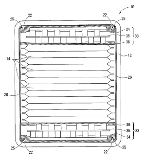
With reference to Figure 1, there is shown the frontal cross-section of an
example of a stacked electrochemical generator 10. The electrochemical
generator 10 comprises a protective enclosure or casing 12 in which an array
of electrochemical cells 14 are stacked together to form a battery. The
electrochemical cells 14 may be electrically connected in series, in parallel
or
combination thereof depending on the desired voltage and current output. In
the example shown, each electrochemical cell 14 comprises an array of thin
film laminates each comprising at least one sheet-like anode, at least one
sheet-like cathode on a current collecting element, and an electrolyte
separator
interposed between the anode and the cathode.
The performance and service-life of modules or batteries such as the
electrochemical generator 10 are significantly improved by maintaining the
5
CA 02603064 2012-01-12
stack of electrochemical cells 14 in a state of compression. An even
distribution
of pressure on the stack of electrochemical cells 14 increases the quality of
the
interface contacts between anode, separator and cathode of each laminate
included in each electrochemical cell 14.
Specific to the present invention, the electrochemical generator 10 includes a
pressure producing apparatus 33 positioned at each end of the stack of
electrochemical cells 14, to maintain the array of stacked electrochemical
cells
1'4 in a state of compression while the cyclical changes in the total volume
of the
stack of electrochemical cells 14 occur during charge and discharge. In the
specific example illustrated in Figures 1 and 2, the pressure producing
apparatus
33 is formed of a rear plate 34, a pressure plate 36, and a spring plate 35
located
in between plates 34 and 36 which provides the compressive force required to
maintain pressure on the two extremities of the stack of electrochemical cells
14
while cyclical volume changes occur. The rear plates 34 at each extremities of
the stack of electrochemical cells 14 are provided with indents or grooves 22
in
which the hook portion 25 of anchoring devices 26 are received. Anchoring
devices 26 maintain rear plates 34 at a predetermined distance from one
another
thereby maintaining the stack of electrochemical cells 14 under an initial
minimum pressure which increases as the volume of cells 14 increases during
discharge and compresses spring plates 35. In this specific example, there are
two anchoring devices 26 located on either sides of the stack of
electrochemical
cells 14.
As illustrated in Figure 3, the anchoring device 26 comprises a hook portion
25 at
its extremity and a main body 27 bearing the tension load of the compressed
electrochemical cells. Hook portion 25 is moored to the outer edge 38 of the
groove 22 of plate 34. Outer edge 38 is preferably designed to mate with the
inner contours of the hook portion 25 to evenly distribute the force generated
by
the compressed electrochemical cells over the hook portion 25. Anchoring
device
26 is preferably made of tempered steel such as ASTM Al 09 or spring steel
such
as 1095 or 1075 carbon steel.
6
MBDOCS_5771715.1
CA 02603064 2007-09-28
WO 2005/109544 PCT/CA2005/000673
Referring back to Figure 2, one embodiment of the anchoring device 26 is a
single steel plate wherein the upper and lower edges have been folded to form
hook portions 25 which extend the entire length of anchoring device 26. The
central portion of the single steel plate may be hollowed to reduce the weight
of
anchoring device 26 without significantly weakening it. In Figure 2, the
central
portion or main body 27 of anchoring 26 comprises three openings 29 which
form four load bearing members 28 that maintain the rear plates 34 within a
predetermined distance from one another.
Figure 4 illustrate the simple process of assembling anchoring devices 26 with
holding members 34. The pressure producing apparatus 33 are positioned at
each end or extremities of the stack of electrochemical cells 14 as shown in
Figure 1, this pre-assembly is then compressed by an hydraulic press or any
other means to a predetermined pressure. While maintaining the pressure on
the pre-assembly, the anchoring devices 26 are slid into the grooves 22. The
pressure of the hydraulic press is released and the anchoring devices 26
maintain the stack of electrochemical cells 14 under pressure.
Since all electrochemical cells 14 do not have the exact same initial
thickness,
the distance between the holding members 34 of a pre-assembly may vary
substantially for a given target pressure. To accommodate this variation of
thickness of electrochemical cells 14 within the established tolerances which
is
compounded when a plurality of cells 14 are stacked together, a series of
anchoring devices 26 of different lengths within the range of minimum and
maximum distance between the holding members 34, is available to match the
actual distance or length of the pre-assembly held under the target pressure.
It is also possible to use shimming plates of specific thickness and of equal
surface areas to the electrochemical cells 14 to compensate the difference
between the actual distance or length of the pre-assembly held under the
target
pressure and the available lengths of anchoring devices 26. The pre-assembly
7
CA 02603064 2012-01-12
is compressed by the hydraulic press to the target pressure, the height of the
pre-
assembly is measured and the hydraulic press is released. This measurement is
used to select the closest length of anchoring devices 26 from the available
lengths of anchoring devices. If the available lengths of anchoring devices do
not
match the measured height within certain tolerances, a slightly longer
anchoring
device 26 is selected and a shimming plate of a specific thickness is added to
the
pre-assembly to fill in the gap between measured height of the pre-assembly
and
the chosen length of the available anchoring device 26.
Figure 5 illustrates another embodiment of a retaining apparatus comprising
rear
plates or holding members 34 positioned at each extremity of the assembly of
electrochemical cells 14 and a plurality of anchoring devices 37 instead of a
single anchoring device 26 on each side of the stack of electrochemical cells.
Each individual anchoring device 37 comprises a main body 39 bearing the
tension load of the compressed electrochemical cells and hook portions 25 at
its
extremities for mooring to the groove 22 of holding members 34. The
manufacturing of anchoring devices 37 is simpler but their assembly onto the
pre-
assembly stacked of electrochemical cells 14 is more time consuming since each
anchoring device 37 must be assembled individually.
Figure 6 illustrates a variant or another embodiment in accordance with the
invention. There is shown an electrochemical generator 50 comprising a
protective enclosure or casing 52 in which an array of electrochemical cells
14
are stacked together to form a battery. Electrochemical generator 50 includes
a
single pressure producing apparatus 33 positioned at one end of the stack of
electrochemical cells 14 and a holding member 54 at the other end thereof.
The stacked electrochemical cells 14 are maintained in a state of compression
by
anchoring devices 56 which may be either anchoring devices 26 as shown in
Figure 2 or anchoring devices 37 as shown in Figure 5. Figure 6 illustrates
that it
is not essential to have a pressure producing apparatus at each extremity
8
MBDOCS-5771719.1
CA 02603064 2007-09-28
WO 2005/109544 PCT/CA2005/000673
of the stack of electrochemical cells 14. A single pressure producing
apparatus
33 may be used to accommodate the cyclical changes in the total volume of the
stack of electrochemical cells 14 occurring during charge and discharge.
Although various embodiments have been illustrated, this was for the purpose
of describing, but not limiting, the invention. Various modifications will
become
apparent to those skilled in the art and are within the scope of this
invention,
which is defined more particularly by the attached claims.
9