Language selection

Search

Patent 2603516 Summary

Third-party information liability

Some of the information on this Web page has been provided by external sources. The Government of Canada is not responsible for the accuracy, reliability or currency of the information supplied by external sources. Users wishing to rely upon this information should consult directly with the source of the information. Content provided by external sources is not subject to official languages, privacy and accessibility requirements.

Claims and Abstract availability

Any discrepancies in the text and image of the Claims and Abstract are due to differing posting times. Text of the Claims and Abstract are posted:

  • At the time the application is open to public inspection;
  • At the time of issue of the patent (grant).
(12) Patent: (11) CA 2603516
(54) English Title: IMPACT PADS AND A PROCESS FOR MANUFACTURING THE SAME
(54) French Title: ELEMENTS D'IMPACT ET PROCESSUS POUR LES FABRIQUER
Status: Deemed expired
Bibliographic Data
(51) International Patent Classification (IPC):
  • B65G 15/62 (2006.01)
  • E01F 15/04 (2006.01)
  • F16F 7/00 (2006.01)
(72) Inventors :
  • YAVER, IMAM SYED (India)
(73) Owners :
  • TEGA INDUSTRIES LIMITED (India)
(71) Applicants :
  • TEGA INDUSTRIES LIMITED (India)
(74) Agent: LAVERY, DE BILLY, LLP
(74) Associate agent:
(45) Issued: 2014-12-23
(86) PCT Filing Date: 2006-06-13
(87) Open to Public Inspection: 2007-05-18
Examination requested: 2011-02-14
Availability of licence: N/A
(25) Language of filing: English

Patent Cooperation Treaty (PCT): Yes
(86) PCT Filing Number: PCT/IN2006/000197
(87) International Publication Number: WO2007/054959
(85) National Entry: 2007-10-02

(30) Application Priority Data:
Application No. Country/Territory Date
1017/KOL/2005 India 2005-11-08

Abstracts

English Abstract


An impact pad comprising an upper part (2), a middle part (3), and a lower
part (4), the said upper part being configured as a single piece with a
plurality of protrusions (2B) on a under side there of facing the middle part,
such that said protrusions are adapted to fit in to the grooves (3A) provided
on the top surface of the middle part, the bottom surface of the middle part
being provided with the third part, namely .means for fastening impact pads on
the main support frame with clamps.


French Abstract

La présente invention vise un élément d~impact comprenant une partie supérieure (2), une partie centrale (3) et une partie inférieure (4), ladite partie supérieure étant configurée sous la forme d~une pièce unique avec une pluralité de protubérances (2B) sur le dessous faisant face à la partie centrale, de sorte que lesdites protubérances soient conçues pour s~ajuster dans les rainures (3A) réalisées sur la surface supérieure de la partie centrale, la surface inférieure de la partie centrale étant dotée d~une troisième partie, c~est-à-dire d~un moyen servant à fixer les éléments d~impact sur le cadre de support au moyen de pinces.

Claims

Note: Claims are shown in the official language in which they were submitted.

CLAIMS
1. An impact pad comprising:
an upper part;
a middle part coupleable to the upper part; and
a lower part coupleable to the middle part,
wherein the upper part comprises a single piece with at least two spaced-apart
lugs on
an under side thereof facing the middle part,
wherein the middle part comprises a single piece with at least two spaced-
apart grooves
provided on a top surface thereof facing the upper part and positioned with
respect to the at
least two spaced-apart lugs,
wherein the lugs of the upper part are adapted to be pushed and to fit into
the grooves of
the middle part in a push fit arrangement, and
wherein the lower part comprises a single piece including a clamping
arrangement to
fasten the impact pad on a main support frame to pad impact.
2. The impact pad of claim 1, wherein an upper side of the upper part is
curved.
3. The impact pad of claim 1, wherein the push fit arrangement has
different geometrical
shapes and designs.
4. The impact pad of claim 1, wherein the upper part is made of Ultra High
Molecular
Weight Poly Ethylene (UHMWPE) and the middle part is made of rubber.
5. The impact pad of claim 1, wherein the impact pad is manufacturable in
different
lengths, thickness and shapes.
4

6. The impact pad of claim 1, further comprising adhesive positioned
between the upper
part and the middle part.
7. The impact pad of claim 1, wherein the clamping arrangement comprises
two
longitudinal grooves on a bottom surface of the lower part.
8. The impact pad of claim 1, wherein the upper part comprises a single
piece consisting
of two spaced-apart lugs, wherein the middle part comprises a single piece
consisting of two
spaced-apart grooves, and wherein the two spaced-apart lugs of the upper part
are adapted to be
pushed and to fit into the two spaced-apart grooves of the middle part.

Description

Note: Descriptions are shown in the official language in which they were submitted.


CA 02603516 2007-10-02
WO 2007/054959 PCT/IN2006/000197
TITLE OF THE INVENTION. Impact pads and a process for manufacturing the same
FILED OF THE INVENTION.

The invention relates to impact pads and a process for manufacturing the same.
BACKGROUND OF THE INVENTION AND PRIOR ART.

Impact pads are known to comprise of fusion of three different parts/layers,
an upper
part/ layer made of Ultra High Molecular Weight Polyethylene (UHMWPE). The
middle
part / layer is of rubber while the lower part / layer is for fastening impact
pads on the
main support frame with clamps.

The fusion of three parts/layers is done by hot vulcanized process in a press.
The
moulds of different sizes are used in the above process to get the desired
product.
However, the existing product has the tendency of bending on both sides of the
impact
pads due to differential shrinkage of Polymer, Rubber and Reinforcements.

Further, in the event that any of the part / layers wears out, the entire pad
has to be
discarded or changed. Also the pads are not cost-effective, as they are
manufactured
by fusion of the three layers which is time-consuming.

OBJECTS OF THE INVENTION.

It is therefore an object of this invention to propose impact pads with a
novel fixing
system.
It is a further object of this invention to propose impact pads having shapes
and sizes,
which can be varied according to requirement.

These and other objects of the invention will apparent from the ensuing
description when
read in conjunction with the accompanying drawings.

BRIEF STATEMENT OF THE INVENTION
.Thus according to this invention' is provided an impact pad comprising an
upper part, a
middle part, and a lower part, the said upper part being configured as a
single piece with
a plurality of protrusions on a under side there of facing the middle part,
such that said

1


CA 02603516 2007-10-02
WO 2007/054959 PCT/IN2006/000197
protrusions are adapted to fit in to the grooves provided on the top surface
of the middle
part, the bottom surface of the middle part being provided with the third
part, namely means
for fastening impact pads on the main support frame with clamps.

This fastening arrangements is unique. The push fit arrangement can have
different
geometrical shapes and design with similarly matching portion in rubber to
fitting method by
simple pushing.

The middle part / layer as shown in the drawing forms a slotted design and
push fit with
upper part / layer is unique and can have different geometrical shapes and
design with
similarly matching on the upper part/ layer and process of fitting by push
fit.

The upper part / layer is made of material such as ultra high molecular weight
polyethylene
(Ul-IE~~;+JVPF_) and the middle part / layer is made of Rubber. T hF lower
part I layer has
clamping arrangement for fastening the impact pad on the main support
frarr;t..

Ir, preferred embodiments according to the invention, the innpact pads are
manufactured in
different lengths, thickness and shapes according to the particular
requirement and all such
embodiments are within the scope of the instant application.

In an optional embodiment, adhesive may be used between the upper and middle
layer.
BRIEF DESCRIPTION OF THE ACCOMPANYING DRAWINGS.

The invention is now described with reference to the accompanying drawings in
which:
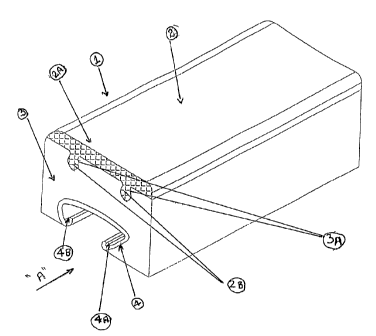
Figure 1 shows fragmentary Isometric view of the proposed pads giving details
and view of
upper part, middle part and lower part..

Figure 2 shows front view of the impact pad along the arrow A shown in figure.
1.
Figure 3, shows the front view of the impact pad shown in figure 2.

Figures 4a to 4d show various types of the lower part namely the clamp
arrangements used
with different lengths and thickness.

Figure 5 shows two segments of the proposed impact Pads.
2


CA 02603516 2007-10-02
WO 2007/054959 PCT/IN2006/000197
DETAILED DESCRIPTION OF THE FIGURES OF THE ACCOMPANYING
DRAWINGS.

Figure no 1 shows an isometric view of the impact pad (1) of the invention..
It has three parts, namely an upper part (2), middle part (3) and lower part
(4).

The upper part is made of material such as ultra high molecular weight
polyethylene. ( MIlVIPE).

As seen from a preferred embodiment of the drawings, the top surface of the
upper part is slightly curved, (2A) and the under surface has two
downwardly extending lugs, (2B,2B ).

These lugs are adapted to snugly fit into the corresponding grooves (3A), on
the upper part of the middle part (3). The middle part is made of rubber.

The number of the grooves correspond to the number shape and
configuration of the downwardly extending lvgs of the upper part. However,
two lugs and the two complementary grooves are preferred for a proper
fitting .

The lower part, (4) is the fastening means for fastening the impact pad on to
the main support frame. It has longitudinal grooves (4A) and (4B) and can
be of any convenient shape as shown in figures 1,2,3,4a 4b,4c and 4d

The different parts are preferably made separately assembled by a unique
push-fit action.

If any one or more part/s is/are damaged, this can be easily replaced without
having to discard the whole pad.

This saves cost and time and is also economical.
3

Representative Drawing
A single figure which represents the drawing illustrating the invention.
Administrative Status

For a clearer understanding of the status of the application/patent presented on this page, the site Disclaimer , as well as the definitions for Patent , Administrative Status , Maintenance Fee  and Payment History  should be consulted.

Administrative Status

Title Date
Forecasted Issue Date 2014-12-23
(86) PCT Filing Date 2006-06-13
(87) PCT Publication Date 2007-05-18
(85) National Entry 2007-10-02
Examination Requested 2011-02-14
(45) Issued 2014-12-23
Deemed Expired 2019-06-13

Abandonment History

There is no abandonment history.

Payment History

Fee Type Anniversary Year Due Date Amount Paid Paid Date
Application Fee $400.00 2007-12-17
Maintenance Fee - Application - New Act 2 2008-06-13 $100.00 2008-06-06
Maintenance Fee - Application - New Act 3 2009-06-15 $100.00 2009-02-23
Maintenance Fee - Application - New Act 4 2010-06-14 $100.00 2010-06-08
Request for Examination $800.00 2011-02-14
Maintenance Fee - Application - New Act 5 2011-06-13 $200.00 2011-02-14
Maintenance Fee - Application - New Act 6 2012-06-13 $200.00 2012-05-04
Maintenance Fee - Application - New Act 7 2013-06-13 $200.00 2013-05-16
Maintenance Fee - Application - New Act 8 2014-06-13 $200.00 2014-06-05
Final Fee $300.00 2014-10-07
Maintenance Fee - Patent - New Act 9 2015-06-15 $200.00 2015-06-08
Maintenance Fee - Patent - New Act 10 2016-06-13 $250.00 2016-06-06
Maintenance Fee - Patent - New Act 11 2017-06-13 $250.00 2017-06-06
Owners on Record

Note: Records showing the ownership history in alphabetical order.

Current Owners on Record
TEGA INDUSTRIES LIMITED
Past Owners on Record
YAVER, IMAM SYED
Past Owners that do not appear in the "Owners on Record" listing will appear in other documentation within the application.
Documents

To view selected files, please enter reCAPTCHA code :


To view images, click a link in the Document Description column. To download the documents, select one or more checkboxes in the first column and then click the "Download Selected in PDF format (Zip Archive)" or the "Download Selected as Single PDF" button.

List of published and non-published patent-specific documents on the CPD .

If you have any difficulty accessing content, you can call the Client Service Centre at 1-866-997-1936 or send them an e-mail at CIPO Client Service Centre.


Document
Description 
Date
(yyyy-mm-dd) 
Number of pages   Size of Image (KB) 
Claims 2007-10-02 2 116
Abstract 2007-10-02 1 63
Drawings 2007-10-02 3 214
Description 2007-10-02 3 132
Cover Page 2007-12-20 2 44
Representative Drawing 2007-12-20 1 12
Claims 2013-07-25 2 44
Claims 2014-04-08 2 45
Representative Drawing 2014-11-27 1 11
Cover Page 2014-11-27 1 41
PCT 2007-10-02 3 95
Assignment 2007-10-02 4 106
Fees 2008-06-06 1 46
Fees 2009-02-23 1 47
Prosecution-Amendment 2011-02-14 1 30
Prosecution-Amendment 2013-01-30 3 99
Prosecution-Amendment 2013-07-25 5 150
Prosecution-Amendment 2013-11-15 2 46
Prosecution-Amendment 2014-04-08 4 105
Correspondence 2014-10-07 1 39