Note: Descriptions are shown in the official language in which they were submitted.
CA 02603538 2007-10-03
WO 2006/110700
PCT/US2006/013396
- 1 -
IMPROVED SYSTEM FOR THE DETECTION OF TRACE VAPORS
AND PARTICLES IN AIR
Field of Invention
The subject invention relates to detection systems for the detection of trace
vapors and
particles in air. It is particularly directed to the detection of traces of
contraband materials
such as explosives and illicit drugs.
Discussion of Related Art
The recent increased threat to society from improvised explosive devices
(IEDs) and
illicit drug traffic has lead to the development of extremely sensitive
systems for the detection
of traces of vapors and particles from explosives and drugs. GE Security and
Smiths
Detection market such systems, for example. Examples of prior art are
described in U.S.
Patents 5,491,337; 6,708,572 and 6,642,513. Equipment is available for hand
search, desktop
operation and walkthrough portal security applications.
One prior art system, described in U.S. patent 5,491,337, draws air from the
vicinity
of a suspect package or person and detects the target vapors in an ion
mobility detector. This
detector cannot tolerate water vapor, concentrations such as commonly exist in
the
atmosphere. Consequently, a dimethyl silicone membrane was deployed to largely
prevent
the passage of water vapor and other atmospheric contaminants while allowing
the passage of
at least a portion of the target vapors. Unfortunately the silicone membrane
allows less than
10% of the sample vapor through to the detector. Furthermore, the membrane
does not
readily capture particles and many particles such as marijuana leaf particles
pass through the
system without being detected.
Prior art detection systems rely on the fact that trace amounts of contraband
will be
transferred to the body of a person who had handled the contraband and
subsequently will be
transferred from the body to any article the person may be carrying (e.g.,
handbag or
suitcase). Trace amounts of contraband have been collected for analysis by
wiping a small
paper or fabric sample pad across the handbag or suitcase with or without the
aid of a vacuum
pump. The prior art sample pad then is inserted into a detection apparatus
where the pad is
CA 02603538 2014-01-10
50860-115
- 2 -
heated to evaporate any particles and condensed vapors. The liberated vapor
then is carried
into the detector that is capable of detecting and identifying the target
vapor.
An existing system is illustrated schematically in FIG. 1. This prior art
system
of FIG. 1 is similar to the system described in greater detail in the above
referenced
U.S. Patent 5,491,337. The prior art system of FIG. 1 analyzes samples that
are collected on
sample wipes consisting of a clean porous filter paper. These wipes are
dropped into a
thermal desorber, 12, in FIG. 1. Desorbed material is carried into the
detector by the action of
a sampling pump, 14. The sample air is drawn into the detector, 16, over a
dimethyl silicone
membrane, 18. Organic vapors diffuse through the semi permeable membrane and
are carried
into the detector on a stream of dry air. The detector may be an Ion Mobility
Spectrometer
(IMS) or an Ion Trap Mobility Spectrometer (ITMS). The dimethyl silicone
membrane
prevents all dust, dirt, and most of the atmospheric water vapor and oxides of
nitrogen from
reaching the detector. Unfortunately, the membrane, 18, is only a few percent
efficient at
transferring the materials of interest and this limits the ultimate
sensitivity of the apparatus.
SUMMARY OF INVENTION
Some embodiments of the subject invention may provide a detection system
that detects trace amounts of both vapors and particles from target materials
without the
necessity of employing sample traps to acquire the sample. This enables
automatic testing of
both people and baggage without human intervention in the sampling process.
Some embodiments of the subject invention may increase the sensitivity of the
detection system by allowing a greater proportion of the target material to
reach the detector.
This has the effect of increasing sensitivity and enables the extremely low
volatility materials
such as the plastic explosives to be detected by their vapor emissions. This
also reduces the
need to detect particulate contamination that may be present from previous
contact or from
secondary, innocent transfer. Vapor emissions are more indicative of the
presence of
contraband than is the presence of particulate material. Some embodiments of
the subject
invention may differentiate whether a response is from vapors or particles.
CA 02603538 2014-01-10
50860-115
- 3 -
Some embodiments of the subject invention will find use in hand held sniffers
and fixed installation portal and baggage inspection systems for the detection
of contraband
material. It is a further feature of some embodiments of the subject invention
that continuous
real time detection is achieved. This increases the speed of the detection
process, and hence
throughput of test articles or people, which in turn reduces the cost of the
inspection and
inconvenience.
U.S. Patent 6,073,499 discloses a portal detection system that relies on the
natural thermal plume generated in proximity to the human body to carry
particles and vapors
into a detector system mounted above the head of the subject under inspection.
This method
proved to be an improvement over previous sampling systems that relied on
induced air
curtains to carry the target vapors and particles into the detector. However,
the human plume
begins at knee level and is comparatively slow until it reaches mid torso when
flow velocities
approaching a meter per second are achieved. It is a further feature of some
embodiments of
the subject invention to provide faster transport of trace materials into a
detector system
without diluting the sample available.
Some embodiments of the subject invention are directed to the sample
acquisition and efficient transfer to a known detector such as an Ion Mobility
Spectrometer or
an Ion Trap Mobility Spectrometer (see U.S. Patents 5,200,614; 6,765,198; and
6,690,005) or
other detector commonly used for detection of trace organic materials. Some
embodiments of
the subject invention are used in a similar configuration to that described in
the above prior art
and shown in FIG. 1. A major improvement in some embodiments of the subject
invention is
provided by replacing the dimethyl silicone membrane with a micro porous
filter element, 21
shown in FIG. 2.
Some embodiments of the subject invention also address improvement of the
efficiency of the sampling process by providing a curtain of warm air through
which the
object or person is caused to pass. The warm air plume is applied at floor
level and is
arranged to be less than the natural human thermal plume that exists at
shoulder level. Vapors
and particles released into this warm air curtain are carried upwards into the
detection system
CA 02603538 2015-03-26
50860-115
- 3a -
inlet. The temperature and flowrate of the warm air plume is controlled so
that it is not
additive to the human plume, but reduces the transport time from shoe level.
In a baggage
inspection station, the warm air plume carries trace materials from the
baggage to a detector in
much the same way as the human body plume in the portal inspection system.
According to one embodiment of the present invention, there is provided a
detector for the detection for trace vapors and particles in the air
comprising: a housing; at
least one well formed in the housing, the well having an open end and a closed
end; a heated
filter positioned across the open end of the at least one well; a sampled air
source delivering
sampled air substantially perpendicular to the open end of the at least one
well on a first side
of the filter; a dry air source to supply dry air across the first side of the
filter at a first
pressure; a detector line in communication with the at least one well on a
second side of the
filter; and a second dry air source for supplying air to a second side of the
filter opposite the
first side at a second pressure lower than the first pressure.
According to another embodiment of the present invention, there is provided a
method for the detection for trace vapors and particles in air, the method
comprising the steps
of: drawing sampled air against a heated filter to create a substantially
stagnant boundary
layer against the surface of the filter; introducing dry air into the boundary
layer; creating
reduced pressure at a second side of the filter sufficient to induce a small
air flow through the
filter but insufficient to eliminate the boundary layer of dry air at a first
side of the filter; and
drawing the air that has passed through the filter into a detector.
DETAILED DESCRIPTION OF PREFERRED EMBODIMENT
FOR LOW SAMPLE FLOWS
Sampled air is drawn in through an inlet tube, 22, shown in FIG. 2, by the
action of a pump, 23. In order to prevent damp air being drawn into the
detector, the subject
invention
CA 02603538 2007-10-03
WO 2006/110700
PCT/US2006/013396
-4 -
incorporates a clean dry air supply that is arranged to flood the inlet side
of the porous filter
element, 21. Sampled air passing down the inlet tube, 22, impinges on the
porous filter
element and turns back through the concentric tube, 24, before continuing on
to the pump, 23.
The impinging sampled air would normally produce a boundary layer of stagnant
air close to
the surface of the porous filter, 21. Dry air is injected into this boundary
region through an
array of jets, 25, arranged in a ring at the surface of the filter element,
21. This dry air is
drawn through the filter element, 21, by.the action of a pump, 26. The
pressure drop across
the filter element, 21, is arranged to be sufficiently small that only a very
small flow is
induced through the filter element, and the boundary layer is not totally
removed. The air
passing through the filter element, 21, is drawn through the detector, 29 and
then to the pump,
26. The volume of the filter element and connecting pipe, 32, to the detector
is kept small so
that the transit time from the filter to detector is less than one second. The
pumping speed of
the pump, 26 is controlled to ensure that the optimum flow through the filter
element, 21, is
achieved.
The filter element, 21, may be made of any appropriate material or materials
and
method of construction, but preferably is a good conductor that is also
chemically inert at
temperatures up to 300 degrees centigrade. In a preferred embodiment, the
filter element, 21,
ensures that particles as small as one micron are stopped within the filter.
Sintering is a well
known technique for making such microporous filtration elements, a commonly
used material
being sintered bronze. Bronze filters are available in various shapes,
including discs and
cylindrical forms, and may be gold plated in some cases. The filer element,
21, may also be
made of stainless steel, whether woven, felted, pressed into sintered discs,
or prepared in any
other appropriate manner. In one embodiment, the filer element, 21, may be an
aluminum
filter made by compressing aluminum powder of controlled particle size in a
die press.
The filer element, 21, is preferably, but not necessarily, no more than 2 or 3
mm thick,
as greater thicknesses will tend to increase transport time through the
filter.
Most of the sampled air passing down the inlet tube, 22 does not impact the
surface of
the filter element because of the blanketing effect of the dry air curtain,
25. However,
particles and heavy molecules have greater momentum than the lighter air
molecules and will
penetrate further into the boundary layer of dry air and are drawn into the
filter element
together with the dry air. The sampled air flow, dry air flow, filter flow,
and distance from
the end of the inlet tube, 22, to the surface of the filter, 21, all influence
the transmission of
CA 02603538 2007-10-03
WO 2006/110700
PCT/US2006/013396
- 5 -
vapors, particles and unwanted light molecules such as the oxides of nitrogen
and water
vapor. In order to optimize the transmission of target vapors and particles,
while largely
eliminating unwanted water vapor and oxides of nitrogen, both pumps, 23 and 26
may be
switched on and the following setup procedures adopted:
1 Set the sample flow at pump, 23, to a flowrate that ensures the largest
particles of
interest are carried along in the air stream and the sampling rate will
provide a representative
sample from the object under inspection. For example for a hand held sniffer,
a flowrate of 1
to 2 litres per minute is typical. When testing hand carried airline bags in
an automatic test
station, 100 to 200 litres per minute will be required. Portal tests demand
that the air close to
the body is efficiently sampled in a few seconds, and prior art methods have
been adopted
which sample at rates in excess of 600 litres per minute.
2 Set the vacuum produced by pump, 26, to ensure a fast response is obtained
to a
target vapor source applied to the inlet, 22.
3 Set the dry air flow, Fl in FIG. 2, on control valve, 27, to a level that
largely
eliminates the response to water vapor in the detector.
4 Adjust the distance from the sample inlet, 22, to the filter, 21, until the
response to
the lightest target vapor, e.g., ethylene glycol dinitrate, is just obtained.
These parameters are interdependent and an iterative process may be required
in order
to reach the optimum settings. Once the flowrates and parameters have been
set, no further
adjustment is required.
In a practical system such as is shown in FIG. 2, a dopant vapor may be
required to
. provide ionic charge moderation as described in U.S, Patent 5,491,337. A
small flow of dry
air is conveniently provided through a dopant chamber, 28, where vapor
diffusing from a
diffusion capsule is carried into the air entering the detector, 29. Also, it
may be preferable to
supply a flow of dry air down the drift tube of the detector at the opposite
end of the detector
from the sample inlet. This may be controlled such as is shown in FIG. 2 with
a control
CA 02603538 2007-10-03
WO 2006/110700
PCT/US2006/013396
- 6 -
valve, 36. The flowrate of the drift gas may be monitored such as by
flowmeter, F3. All
three dry gas flows can be conveniently provided by passing the effluent of
the pump, 26,
through a drying system, 30. This may be a simple tube packed with drying
material such as
molecular sieve, or alternatively any other automatic drying system may be
employed, such
as that described in U.S. Patent 6,642,513, and shown in FIG. 3. The system of
FIG. 3 has
two drying tubes, A and B, one of which is hot and purging to atmosphere while
the other is
drying the gas supply to the apparatus. The two tubes are caused to alternate
between drying
and purging, thus maintaining a continuous supply of clean dry air to the
apparatus.
Much of the dried air is exhausted to atmosphere at the front of the filter
element, 21,
shown in FIG. 2. A make up airflow intake, F2 is provided at the vacuum side
of the pump,
26 and is controlled either by a flow restriction, or valve, 31. The make up
air stream is
likely to be greater than the flow Fl injected into the front of the filter
element when an
automatic dryer system is in use, since some air is also exhausted through the
dryer tube
being purged to atmosphere.
In operation, air around or within the test object may be sampled by directing
the inlet
nozzle to the proximity of the threat. Contraband materials such as explosives
and illicit
drugs emit extremely low levels of vapor, and may release micro particles into
the
atmosphere, particularly if stimulated such as by vibration. Any particles and
vapor entrained
in the sample air stream entering the detection system impact the filter
element due to their
higher momentum than the incoming air stream. The filter may be maintained at
an elevated
temperature between 150 and 300 degrees Celsius to allow transmission of the
low volatility
target vapors, and to rapidly evaporate any particles. It is preferable to
make the filter
element of high thermal conductivity material such as sintered aluminum or
bronze. This
ensures that the filter will remain at a high temperature even when a cool
stream of air is
directed at it. The dry air curtain may be pre heated in the housing, 34,
shown in FIG. 2, and
also may act to maintain the filter at the elevated temperature. Target
molecules that are
drawn through the filter are carried into the detector through a short heated
tube, 32. The
filter housing, connecting tube and detector may all be maintained at elevated
temperature
and insulated by thermal insulation material, 33.
The preferred mode of operation allows for sample to be acquired, and then the
pump,
23, to be shut off. This has several advantages in that continuous sampling
tends to clog the
= filter, 21, and also reduces the filter temperature. Low filter
temperature causes poor
RECTIFIED SHEET (RULE 91)
IS NEP
CA 02603538 2007-10-03
WO 2006/110700
PCT/US2006/013396
- 7 -
transmission of sample, and slows clear down after material is detected. The
intermittent
mode of operation further reduces the total amount of water vapor entering the
detector. It
also allows the response from particles and vapors to be differentiated.
Particulate response
clears down much more slowly than a vapor response after the pump is switched
off. This is
easily recognized by the operator, but can also be automatically determined by
a software
algorithm operating on the detector signal.
DETAILED DESCRIPTION OF PREFERRED EMBODIMENT FOR PORTAL
DETECTION, AND AUTOMATIC BAGGAGE INSPECTION
The detection of vapor and particle emissions from the whole body of a person
generally requires sample flows of approximately 10 to 30 litres per second in
order to
complete the test in a few seconds. Such flow would require sampling tube
diameters of
approximately 50 to 90 mm in order not to cause a high vacuum at the filter
element. High
vacuum levels cannot be tolerated, however, since the detector itself has to
be operated below
the inlet filter pressure, but near to atmospheric pressure, and this is
problematic. The
maintenance of an efficient dry air curtain across diameters of 50 to 90 mm is
also extremely
difficult. Furthermore, it becomes impossible to maintain the temperature
across a large filter
element when heating by conduction from the periphery.
In order to overcome these problems, a preferred embodiment for portal and
automatic baggage configuration has been devised. This incorporates a
multiplicity of
smaller filter elements arranged in an array in a manifold system. The
incoming sampled air
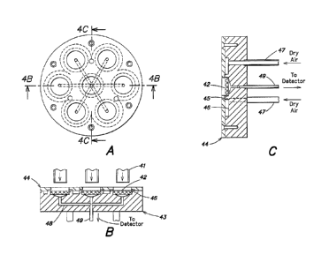
stream is directed down several parallel tubes, 41, shown in FIG. 4. In the
example
illustrated, an array of seven parallel tubes is shown arranged in line with
an array of seven
filter elements acting as sample impacters as described in the detailed
description of the
preferred embodiment for low sample flows. It should be understood that other
numbers of
tubes and tube arrangements may also be employed.
In this embodiment, a curtain of dry air is generated in front of each filter
element in
the same way as described in the previous section, but a novel means of
providing a
multiplicity of air curtains has been devised. The housing for the filters is
comprised in two
parts, shown in section in FIG. 4. The filters, 42, are held in cylindrical
wells in the housing,
43, and a cover plate, 44, is attached to hold the filters in place and to
provide an air curtain
across each filter element. The filters and holes in the cover plate are
arranged in line with
CA 02603538 2007-10-03
WO 2006/110700
PCT/US2006/013396
- 8 -
the incoming sampled air streams, and around each hole in the cover plate, a
radial array of
grooves, 45, is engineered to provide an air curtain from an array of paths,
46, in the housing,
43. The radial grooves, may be conveniently stamped into the surface of the
cover plate, 44,
in a stamping process using a tool similar to that illustrated in FIG. 5. The
stamping process
is made easier if the housing and cover plate is made of brass or aluminum.
The dry air
paths, 46 may be conveniently milled in the surface of the housing 43 and dry
air supply is
connected into these from the back of the housing. It is preferable to supply
the dry air from
a number of supply points, 47 as shown, so that each ring has the same air
pressure, and all
air curtains are equal.
Air is drawn through each filter element, as previously described, and each
effluent is
connected together as shown in the pathways, 48, in FIG. 4. This is then piped
to the detector
through the heated pipe, 49. The flow through each filter element is
substantially identical
and is controlled by the pressure drop across the filter as described
previously. The flowrate
is controlled to provide a sample transit time of less than one second into
the detector.
An automatic inspection station for the detection of traces of contraband in
airline
bags is shown in FIG. 6. The bags are conveyed through a test area that is
enclosed on four
sides with openings at front and back to allow transport of the bags. The
conveyor is
preferably made from number of independent rollers, 62, shown in FIG. 6,
although other
types of conveyers, such as open mesh designs, may also be employed.
In the roller embodiment, the rollers are driven at a controlled speed that
ensures the
trace detection cycle is complete before the bag emerges from the test
station. A warm air
plume is created from a heating element, 63, arranged in the tunnel below the
rollers or,
preferably, within one of the rollers so that the roller itself is heated. The
air passes through
the gaps adjacent the heated roller, is heated, and rises upwards to the
sample inlets, 64.
The sample inlets may be a multiplicity of tubes as described above and shown
in
FIG. 4, but the preferred embodiment has an array of sample inlet tubes in
parallel across the
conveyor as shown in a cut-away view in FIG. 6. This allows the warm air plume
generated
across the conveyor to rise substantially vertically into the sample inlets.
The sampled air
impacts the filter elements in a manifold, 65, is then drawn into a pump, 68,
through one of
two valves, 66, and 67, at substantially the same flow as the warm air plume.
When no bag is in the test area, the sample air stream is caused to bypass the
detector
inlets by opening the valve, 67, and closing valve 66. By this means, the warm
air plume is
=
CA 02603538 2007-10-03
WO 2006/110700
PCT/US2006/013396
- 9 -
maintained at all times, but the filter elements in the sample inlet system do
not become
blocked. When a bag enters the test area it is detected by a suitable sensor,
such as an optical
beam sensor, the valve 67 is closed and the valve 66 is opened.
It is also advantageous to provide .a vibration means, 69 either on a roller
or under the
conveyor at a position prior to the warm air plume. The vibration causes the
bottom of the
bag in contact with the vibrating roller to lift up and down repeatedly as the
bag passes over
the roller. This in turn causes the bag to ventilate air from inside the bag
into the warm air
stream. A frequency of 5 to 20 cycles per second is chosen to provide the
optimum
ventilation rate from typical hand carried and checked bags. It may also cause
particles
adhering to the outside of the bag to be dislodged and these too are carried
by the warm air
stream into the detection system.
In a preferred embodiment, the inlet flow that is drawn into the detection
system is
arranged to be approximately equal to the warm air stream induced by the
heater, 63. This
provides the least dilution or loss of sample that may be carried in the warm
air stream.
Large bags do interrupt the warm air plume, but the airflow around the
periphery of the bag
increases to maintain a substantially constant flow rising toward the detector
inlet. Most of
the air is ventilated from bags at the periphery of the bag, or from the seam
between the two
halves of a typical suitcase. It is preferable to place all bags so that they
are laid flat (i.e.,
smallest dimension upwards, as shown in FIG. 6) on the conveyor in the same
way as is
required for x-ray inspection of the bags. This facilitates the pumping of a
bag and the
ventilated air is carried directly into the air plume.
In one embodiment of the subject invention, the x-ray inspection and the trace
detection station is combined in the same tunnel. This allows the bags to be
searched for
weapons and contraband materials by the integrated test station.
A preferred embodiment for portal detection of contraband is shown in FIG. 7.
The
detection system was described earlier in reference to FIG. 4. The sample
inlets, 41, shown
in FIG. 4, are connected into a short tube, 71, of approximately 100 mm
diameter, whose
inlet is arranged about two meters above the floor of the portal, 70. A
concentric tube, 72,
approximately 150 mm diameter is mounted around the sample inlet tube, 71, and
acts as a
bypass flow path to direct the sampled air away from the detection system
interface when no
subject is in the portal. Electrically or pneumatically operated gate valves,
76 and 77, control
the direction of the air stream. When valve 77 is open, valve 76 is closed and
the air stream
CA 02603538 2007-10-03
WO 2006/110700
PCT/US2006/013396
- 10 -
bypasses the filter elements described earlier. When a subject enters the
portal, the valve 77
is closed and valve 76 is opened, thus allowing the air passing over the
subject to be sampled
into the detection system.
A warm air plume may be generated within the portal from a heating element in
the
floor of the portal. It is better to avoid a step-up into the portal, but the
warm air stream is
preferably generated below the feet in order to sample the whole body. In the
preferred
embodiment, a fan, 78, and small heater, 79, is arranged in the wall of the
portal and the
outlet is ducted into a small gap between the portal floor and the surrounding
floor level. The
center of the portal floor has an open grill, 73, which allows the warm air to
escape into the
portal. This provides the initial airflow to form the warm air plume.
The grill, 73, is preferably caused to vibrate at sonic or ultrasonic
frequency, but not
at an amplitude which would cause discomfort to the person under test. This
has the effect of
dislodging some particles that may be adhering to the outside of clothing of a
subject
standing on the grill. The vibration causes particles within the test
subject's clothing to
migrate to the outside, and air within the clothing to ventilate, thus
carrying any contraband
particles and vapors into the warm air plume and on to the detector. A ramp
may be provided
at the entrance and exit from the portal, so that no step is necessary into
the portal, and
wheelchairs may access the portal.
In operation, the subject is sensed on entering the portal, optically, by
weight, or
otherwise, and will be directed, such as a traffic control signal or an exit
door, to remain
within the portal until the test is complete. Contraband sample vapors and
particles released
into the warm air plume are quickly carried into the detection system where
they are detected.
Total test time is preferably between 3 and 6 seconds, but clear down from a
positive
response may take longer. If no contraband is detected, the subject is allowed
to continue
through the portal.
It may be convenient to carry out other known inspection processes at the same
time
as the contraband test is made. Weapons detection either by metal detection, x-
ray, or
terahertz scanning can be combined with the trace contraband test. Similarly,
ionizing
radiation monitors can be mounted in the portal to provide detection of
nuclear threat
materials. The signals from all the detection processes can be integrated to
provide an
automatic inspection portal for chemical contraband, weapons and nuclear
threat materials,
=
=
CA 02603538 2007-10-03
WO 2006/110700
PCT/US2006/013396
- 11 -
This invention is not limited in its application to the details of
construction and the
arrangement of components set forth in the following description or
illustrated in the
drawings. The invention is capable of other embodiments and of being practiced
or of being
carried out in various ways. Also, the phraseology and terminology used herein
is for the
purpose of description and should not be regarded as limiting. The use of
"including,"
"comprising," or "having," "containing", "involving", and variations thereof
herein, is meant
to encompass the items listed thereafter and equivalents thereof as well as
additional items.
=