Note: Descriptions are shown in the official language in which they were submitted.
CA 02603593 2007-09-21
TITLE OF THE INVENTION
A REFRIGERATED DISPLAY CASE DOOR AND METHOD OF MANUFACTURE
BACKGROUND OF THE INVENTION
The invention is directed to product display cabinets or cases which are
used in self-service markets, stores, and other establishments in which
products are displayed, viewed, selected and purchased. Such display
cabinets generally operate below external ambient temperature. Typically
such display cabinets include one or more glass paneled doors through which
products on shelves in an interior compartment of the display case can be
viewed.
Typically the closures or doors for such display cabinets include an
insulated glass unit or assembly comprised of a plurality of glass panes
disposed in substantially parallel side-by-side spaced relationship to each
other. Normally spacers maintain the glass panes separated from each other
and a peripheral seal unites the assembly into a unitized glass unit. Door
frames for such glass units have been conventionally formed in many
different ways. In accordance with U.S. Patent No. 3,673,735 issued on July
4, 1972 to Winsler et al., a door frame is made from a plurality of
rectangularly related extrusions made from aluminum or some other suitable
metal. Four pieces cut from one specific extrusion are mitered at the
corners and are welded together to form an outer frame member, as are
four pieces of a different extrusion to form an inner frame member, both of a
generally open polygonal annular configuration. Obviously, such door
frames are undesirable for use in refrigerated display cases because of the
high heat conductivity of metal. More recently metal frames remain utilized
in association with display doors for refrigerated display cases, but thermal
insulating barrier members formed of molded, expanded or extruded plastic
material are placed against the insulated glass unit to increase efficiency
because the barrier members have relatively low heat conductivity.
However, discounting use of a conventional peripheral gasket member, such
display doors still utilize a metallic door frame made of four pieces of
extruded metal mitered at the corners and welded to each other resulting in
decreased heat conductivity, but increased production costs. Even in the
case of a refrigerator door formed from polymeric material, such as disclosed
CA 02603593 2007-09-21
in the patent to Richardson et al. granted on June 8, 1999 under U.S. Patent
No. 5,910,083, the top, bottom and side rail elements are mitered at the
corners and united thereat by bonding to form a generally polygonal annular
door frame. However, for the most part such conventional insulated
display cabinet doors are extremely complex in the manufacture and
assembly thereof resulting in relatively high prices per door at both
wholesale and retail levels.
Conventional doors for refrigerated display cabinets also generally
carry upper and lower outwardly spring-biased pivot pins which enter pivot
openings in the door frame of an associated display cabinet. Insulated doors
are relatively heavy and aligning and inserting the pivot pins into the pivot
openings can be difficult, particularly when the pivot pins are under
relatively
high biasing forces.
BRIEF SUMMARY OF THE INVENTION
The present invention is directed to a novel display cabinet and
particularly to a closure or a door therefor which is defined by four major
components, namely, an outer polygonal annular frame member, an
insulated glass unit, an inner polygonal annular frame member and an inner
polygonal peripheral seal.
In keeping with the present invention, the outer polygonal annular
frame member is a single substantially homogeneous polymeric/ copolymeric
injection molded member, as is also the inner polygonal annular frame
member. The latter construction of the inner and outer polygonal annular
frame members reduce heat conductivity to an absolute minimum, thereby
creating a display door which is highly efficient and relatively inexpensive
to
both manufacture and assemble, as will be more evident hereinafter.
More specifically, the one-piece injection molded
polymeric/copolymeric outer frame or bezel is deflned by radially inwardly
directed inner and outer border portions or flanges and a peripheral wall
therebetween with the inner and outer flanges setting-off respectively larger
and smaller polygonal openings. The insulating glass unit is also polygonal
and is of a peripheral size which can pass through the inner opening of the
outer frame but cannot pass through the outer opening of the outer frame.
2
CA 02603593 2007-09-21
When thus inserted into the outer frame, a peripheral bead of adhesive
between an outer peripheral surface of the insulating glass unit and the
outer flange of the outer frame effectively bonds the same together. A
second bead of adhesive peripheral bonds an inner peripheral surface of the
IG glass unit to an inner peripheral edge of the inner frame while an
outermost edge portion of the inner frame is snap-secured to a flange of the
outer frame to forcefully retain the components in assembled condition
incident to the curing/solidification of the two adhesive beads. In this
manner the door frame of the display door is made from only two major
pieces of material each injection molded from polymeric/copolymeric
material possessing low heat conductivity and through the utilization of two
peripheral adhesive beads and a highly forceful peripheral snap connection
between the inner and outer frames, the IG unit is held rigid until the
adhesive of the two beads cures/sets.
The latter construction provides simplicity of assembly in a relatively
short period of time absent extraneous components, such as separate
fasteners, and utilizes a minimum of major components, namely, four
components defined by the one piece injection molded outer frame, the one
piece injection molded inner frame, the glass unit and the sealing member.
Only two beads of adhesive applied during assembly retain the components
securely bonded together to provide a relatively inexpensive and long-lasting
insulated display door.
The display door just described also includes a pair of conventional
pivot pins in substantially axially aligned relationship biased outwardly at
upper and lower corners of the display door which engage in a pivot pin
guiding and locating member of the invention associated with an opening in
upper and lower walls of the display cabinet door frame. Each opening in
the door frame is of specific configuration to accurately positionally locate
therein the guiding and locating member which includes guide means for
guiding each pivot pin into a pivot opening of the guiding/locating member.
Since each pivot pin and guiding or locating member can be only connected
to the display door frame in one position, each display door can be easily
and accurately assembled by guiding each pivot pin between guiding
surfaces of the guiding or guide member into each associated guide member
3
CA 02603593 2007-09-21
pivot pin opening to assure that each display door is properly pivotably
mounted with respect to the display cabinet.
With the above and other objects in view that will hereinafter appear,
the nature of the invention will be more clearly understood by reference to
the following detailed description, the appended claims and the several views
illustrated in the accompanying drawings.
BRIEF DESCRIPTION OF THE SEVERAL VIEWS OF DRAWINGS
FIGURE 1 is a front perspective view, and illustrates a display cabinet
including a plurality of insulating glass doors, a door frame, one of several
vertical mullions and an interior or interior chamber of the cabinet in which
products are housed and displayed.
FIGURE 2 is an exploded perspective view of the components used to
manufacture each of the display doors of Figure 1, and illustrates from right-
to-left a polygonal annular outer frame, a polygonal bead of adhesive, an
insulating glass unit or assembly, another polygonal bead of adhesive, a
polygonal annular inner frame, and a polygonal sealing member.
FIGURE 3 is a fragmentary exploded cross-sectional view through the
unassembled components of Figure 2, and more specifically illustrates the
cross-sectional configurations thereof and the relationships of the
components to each other.
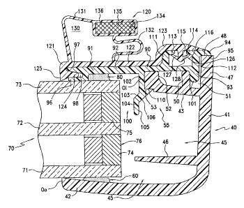
FIGURE 4 is an enlarged cross-sectional view taken through any one
of the display doors of Figure 1 and the display components of Figure 3 when
fully assembled, and illustrates the components in assembled relationship.
FIGURE 5 is a fragmentary perspective view of a corner of one of the
display doors, and illustrates a pivot pin projecting upwardly therefrom.
FIGURE 6 is a fragmentary perspective view of the upper right-hand
corner of the display cabinet frame of Figure 1, and illustrates a pivot pin
guiding and locating member snap-secured in an opening formed in a wall of
the frame member.
FIGURE 7 is a fragmentary front elevational view of the upper right-
hand corner of the display cabinet of Figure 1, and illustrates the pivot pin
of
the display door located in a pivot pin opening of the pivot pin guiding
member.
4
CA 02603593 2007-09-21
FIGURE 8 is an enlarged cross-sectional view taken generally along
line 8-8 of Figure 7, and illustrates the manner in which a conventional
spring biases the pivot pin into the pivot pin opening of the pivot pin
guiding
member.
FIGURE 9 is a top perspective view of the pivot pin guide or guiding
member, and illustrates a guide path defined by inwardly converging
opposing side guide surfaces for directing a pivot pin into the pivot pin
opening of the guide member.
FIGURE 10 is a bottom perspective view of the guide member of
Figure 9, and illustrates oppositely projecting resilient fastening lugs and a
locating slot in a forward peripheral face of a body of the guide member.
FIGURE 11 is a top perspective view of another guide member, and
illustrates an inwardly and upwardly tapering lower guide surface between
inwardly converging opposing side guide surfaces.
FIGURE 12 is fragmentary top plan view looking upwardly in Figure 6,
and illustrates a positional locating opening in an upper horizontal frame
member defined in part by an inwardly projecting locating tab which
registers with a positional locating slot of the guide member.
DESCRIPTION OF THE PREFERRED EMBODIMENT
A novel refrigerated display cabinet, case, walk-in or the like is fully
illustrated in Figure 1 of the drawings, and is generally designated by the
reference numeral 10.
The display cabinet 10 may be, for example, a self-contained
refrigerated unit which, after manufacture, is shipped to a self-service
store,
market or like establishment in which perishable food items are stored on
shelves (not shown) or the display cabinet 10 can be a so-called built-in by
which the cabinet 10 can be framed-out at the use site. In either case, the
display cabinet 10 includes a top wall 11 (Figure 1), opposite substantially
parallel side walls 12, of which only one is shown, and a bottom wall and a
rear wall (not shown) collectively defining an interior product compartment
or chamber 15 which is maintained below outside ambient temperature by a
conventional cooling system (not shown).
CA 02603593 2007-09-21
A front of the display cabinet 10 includes a door frame and door
assembly 20 which is generally of a polygonal configuration, as viewed from
the front, and defines an opening (unnumbered) which is subdivided into a
plurality of individual openings 0 by a plurality of substantially
horizontally
spaced vertical mullions 27. A door frame 30 of the door frame and door
assembly 20 has pivotally mounted therein a plurality of IG glass panel doors
21-25, each identically constructed in accordance with the present invention
and each including upper and lower vertical pivot pins 26 (Figure 5) for
pivoting each door 21-25 to respective upper and lower horizontal extruded
metal frame members 31, 32 (Figures 1 and 6-8) of the frame 30 which also
includes vertical extruded metal end frame members 33 and three additional
substantially identical vertical mullions (not shown) corresponding to the
mullion 27 illustrated in Figure 1 of the drawings. Inboardmost walls
(unnumbered) of the frame members/mullions 31-34 and 27 set-off five
access openings 0, one opening 0 associated with each door 21-25, through
which products in the compartment 15 can be viewed and accessed.
Since the display doors 21-25 are identical, the following description of
the display door 25 and its method of assembly/manufacture will be
considered equally applicable to the display doors 21-24.
The display door 25 (Figures 2, 3 and 4 of the drawings) includes an
outer polygonal annular frame 40, a polygonal bead of bonding or adhesive
material 60, an IG (insulating glass) unit or assembly 70, another polygonal
bead of bonding material or adhesive 80, an inner annular polygonal frame
90 and an inner polygonal sealing member 120.
Of major importance with respect to the present invention is the fact
that the outer polygonal annular frame 40, including a handle H thereof
(Figures 1 and 2), is formed as a single substantially homogenous injection
molded polymeric/copolymeric member which has heretofore been
unprovided in refrigerated display cabinet IG doors. Of equal importance is
the fact that the inner annular polygonal frame 90 is also formed as a single
substantially homogeneous polymeric/copolymeric injection molded member.
Because of the latter construction of the two frames 40, 90 and specific
peripheral walls and relative dimensioning thereof with respect to each other
and with respect to the IG unit 70, the display door 25 is essentially of a
three-piece construction, namely, both frames 40, 90 and the IG unit 70
6
CA 02603593 2007-09-21
imaginatively rigidly bonded together by the strategic location of the
peripheral beads of adhesive material 60, 80, as will be described more
specifically hereinafter.
The outer polygonal frame 40 (Figures 3 and 4) of the display door 25
includes a peripheral wall 41 and an outermost or outer border portion or
flange 42 directed inwardly and defining an outer polygonal opening Oo of a
polygonal configuration. The outer frame 40 further includes an inner or
innermost border portion or flange 43 projecting inwardly from the
peripheral wall 41 and defining a polygonal inner opening Oi which is
appreciably smaller in size than the outer polygonal opening Oo defined by
the flange 42. The peripheral wall 41 and the inwardly directed border
portions or flanges 42, 43 define an inwardly opening peripherally extending
chamber 45 into which interiorly projects a peripherally extending reinforcing
rib 46. A peripheral terminal end wall portion 47 of the peripheral wall 41
terminates in a peripheral terminal end face or surface 48 and defines with a
substantially parallel peripheral wall 50 a continuous inwardly opening
peripheral groove 51. The peripheral wall 43 also includes a terminal
peripheral end wall portion 52 and outboard thereof a peripherally extending
locking face or surface 53 in part defining cooperative snap-securing means
55 (Figure 4) which is associated with the inner polygonal annular frame 90
in a manner to be described more fully hereinafter.
During assembly of the display door 25, the adhesive bead 60 (Figures
2, 3 and 4) is applied to an inner surface (unnumbered) of the flange 42 or
to the IG unit or assembly 70 in the manner evident from Figure 3 of the
drawings. The adhesive of the adhesive bead 60 is quick setting, curing or
drying (within one hour) which is highly desirable for purposes of assembly,
as will be described more fully hereinafter.
The insulating glass unit or assembly 70 is also of a conventional
construction and can include two, three or more pieces of tempered glass,
such as tempered pieces of glass 71, 72 and 73 disposed in substantially
spaced parallel relationship and retained thereat conventionally by spacers
74, 75 appropriately bonded and sealed to the glass pieces 71, 72; 72, 73 to
produce an air-tight IG unit or assembly 70 which may include conventional
infrared reflecting visible light transmitting coatings on one or more
surfaces
thereof, such as disclosed in U.S. Patent No. 4,382,177 granted to James J.
7
CA 02603593 2007-09-21
Heaney on May 3, 1983 and reissued under RE 35,120 on December 12,
1995.
One or more of the inner surfaces (unnumbered) of the tempered
glass pieces 71, 72 and/or 73 may include a metallic strip electrode
electrically conductively bonded to an electric conductive coating on a
surface of one of the glass pieces 71-73 to reduce/eliminate condensation
and/or include a heating element associated with the outer frame 40 in the
manner disclosed in U.S. Patent No. 4,127,765 granted to James J. Heaney
on November 28, 1978. The insulating glass unit 70 includes an exterior
peripheral polygonal surface 76 which corresponds in shape to the shapes of
the openings Oo and Oi, but the peripheral dimensions in both length and
width of the peripheral surface 76 are greater than like dimensions of the
opening Oo of the flange 42 of the outer frame 40, but less than the
dimensions of the opening Oi of the flange 43 of the outer frame 40. The
function of the latter dimensioning is disclosed in the commonly assigned
patent of Herrmann et al. granted on April 20, 2004 under U.S. Patent No.
6,722,083 B2. As more specifically described in the latter patent and
evident in Figure 3, the dimensioning of the peripheral surface 76 of the
insulating glass unit 70 permits the insulating glass unit 70 to be introduced
downwardly as viewed in Figure 3 through the opening Oi of the peripheral
flange 43 into the chamber 45 of the outer frame 40 to the position shown in
Figure 4 with the adhesive bead 60 bonding an inner surface (unnumbered)
of the outer flange or border 42 to an outer surface (unnumbered) of the
outer glass piece 71 during assembly of the display door 25, as will be
described more fully hereinafter.
The adhesive bead 80 (Figures 3 and 4) bonds an inner surface
(unnumbered) of the inner polygonal annular frame 90 to an outer surface
(unnumbered) of the piece of glass 73. More specifically, the inner frame 90
includes a first innermost polygonal peripheral portion 91, an intermediate
peripheral wall portion 92 and an outermost peripheral portion 93 which
terminates in an outwardly directed peripheral terminal wall portion 94
having a face or surface 95 in intimate bearing peripheral sealing
relationship to the end face 48 of the terminal end wall portion 47 of the
outer frame 40. The innermost peripheral wall portion 91 includes two
inwardly directed relatively spaced peripheral leg portions 96, 97 defining
8
CA 02603593 2007-09-21
therebetween an inwardly diverging peripheral groove 98. The peripheral
leg portion 96 intimately sealingly engages an outer surface (unnumbered)
of the glass piece 73 of the IG unit 70 to preclude exodus of the adhesive or
bonding material of the adhesive bead 80 the left, as viewed in Figure 4,
and essentially retains the adhesive 80 positioned as shown in Figure 4. The
outermost peripheral wall portion 93 of the inner frame 90 includes two
outwardly directed peripheral wall portions or flanges 100, 101, the latter of
which seats in the inwardly directed peripheral groove 51 of the outer frame
40 and snugly engages in surface-to-surface contact with the peripheral wall
50 of the flange 43 along two surfaces (unnumbered) thereof, as is readily
apparent in Figure 4.
The peripheral flange 100 is stepped and includes an innermost wall
portion 102, an inclined medial wall portion 103 and an outermost wall
portion 104. The wall portions 104, 103 include respective outermost
peripherally extending surfaces 105, 106 which collectively define a
peripheral guide surface for introducing the peripheral flange 100
progressively into and through the opening 01 of the peripheral flange 43 of
the outer frame 40 until the peripheral flange 100 reaches its fully
assembled and seated position, as shown in Figure 4. The guide surface 105
of the peripheral end portion 104 of the peripheral flange 100 is of a smaller
peripheral dimension than the dimension of the opening 01 while the
peripheral guide surface 106 progressively increases in peripheral size until
reaching a snap-locking peripheral nose 110 forming the second part of the
snap-securing means 55 which eventually intimately engages the locking
face or surface 53 of the peripheral flange 43 of the outer frame 40 under
sufficient force to draw the flange or border 42 of the outer frame 40 and
the inner frame 90 toward each other under the appreciably high resilient
force of the plastic material of the outer and inner frames 40, 90,
respectively, in particular the force created between the respective
peripheral wall portions 43, 102 thereof. This peripheral force particularly
draws the flange 42 of the outer frame 40 and the innermost peripheral wall
portion 91 of the inner frame 90 into intimate forceful contact with the outer
surfaces (unnumbered) of the respective glass pieces 71, 73 squeezing the
adhesive beads 60, 80, respectively, into intimate contact with all opposing
peripheral surfaces to create a very strong bond once the adhesive of the
9
CA 02603593 2007-09-21
adhesive beads 60, 80 has cured or set. The snap-securing means 50
thereby automatically creates a very strong or forceful clamping force which
holds the components 40, 70, 90 assembled absent the use of conventional
clamps, vises or the like, and when fully assembled by applying the inner
polygonal sealing member 120 thereto, very quickly and easily, the display
door 25 can be shipped very shortly after the adhesive beads 60, 80 have
been applied and well before curing thereof which allows packaging and
shipping to continue quickly and inexpensively. It should also be particularly
noted that there are six peripheral areas of contact between the outer and
inner frames 40, 90 and the glass unit 70, namely, at the surfaces 48, 95;
the two surface contacts between the peripheral walls 50, 101; the two
peripheral surface contacts between the terminal peripheral wall portion 52
of the flange 43 and each of the adjacent peripheral surfaces of the flange
portion 102 and the intermediate peripheral wall portion 92 of the inner
frame, and the surface contact between the leg 96 and the outer surface of
the piece of glass 73. The latter six peripheral surfaces of contact render
the
entire door extremely robust and rigidly united, including the formation of a
very tight seal between the peripheral surfaces or faces 48, 95 (Figure 4) to
substantially seal the chamber 45 to atmosphere and reduce ambient air
entry into the chamber 45 to thereby increase cooling efficiency when
associated with the display case 10.
The outer peripheral wall portion 93 of the inner frame 90 includes two
inwardly directed peripheral flanges 111, 112 terminating in opposing noses
113, 114 defining therebetween a peripheral slot 115 and a wider peripheral
chamber 116 which function in a manner to be described more fully
hereinafter with respect to the inner polygonal sealing member or sealing
means 120.
The inner polygonal sealing member or sealing means 120 includes an
innermost or inner peripheral wall portion 121, a medial peripheral wall
portion 122 and an outer or outermost peripheral wall portion 123. The
inner peripheral wall portion 121 includes an outwardly directed peripheral
nose 124 converging outwardly which is received in the groove 98 of the
inner peripheral wall portion 91 of the inner frame 90 and also includes a
peripheral sealing edge 125 which intimately engages the outer surface
(unnumbered) of the glass piece 73 to provide aesthetic appearance thereat.
CA 02603593 2007-09-21
The opposite outer peripheral wall portion 123 of the inner polygonal sealing
member 120 includes a peripheral outwardly directed securing flange 126 of
a generally T-shaped transverse cross-section, whose arms 127, 128
resilient lockirigly engage against the undersides of the noses 113, 114,
respectively, to hold the inner polygonal sealing member 120 intimately
secured to the inner frame 90. The medial portion 122 of the inner
polygonal sealing member 120 includes a hollow chamber 130 defined by
resilient peripheral walls 131, 132 which merge and define another annular
chamber 134 housing conventional magnetic means 135 which are
substantially polygonal in cross-section and with a relatively flat peripheral
wall portion 136 magnetically secure the doors 21-25 closed through
magnetic attraction relative to the various metal frame members and
mullions 27, 33 of the frame 30 (Figure 1) in a conventional manner.
The display door 25 and each of the remaining display doors 21-24 can
either be left-hand or right-hand openings and, in each case, upper and
lower corners (unnumbered) of the doors are provided with conventional
pivot means 150 (Figures 5-8) which can conventionally include a torsion rod
or torque rod 151, the pivot pin 26, a spring 153 for at all times urging a
square pin end portion 154 of the pivot pin 26 outwardly of the outer frame
40 through an opening 155 in the peripheral wall 41 (Figure 8). The pivot
means or pivot assembly 150 thus far described is relatively conventional
but, in keeping with this invention, there is associated with each pivot pin
end portion 154 pivot pin guiding and locating means 160 snap-secured in
an opening 161 (Figure 12) in each of the upper and lower frame members
31, 32, respectively, for guidingly locating the pin end portion 154 into a
polygonal or rectangular opening 162 of the guiding means 160 to ease the
assembly of each display door 21-25 relative to the frame 30.
The guide member 160 includes a top surface 170 (Figure 9), an
opposite bottom surface 171 (Figure 10), and outer peripheral surfaces 172,
173 which are stepped relative to each other with the surface 172 being
larger than the surface 173 and thereby defining a peripheral flange 174.
The flange 174 is interrupted by diametrically oppositely opening slots 175
and aligned therewith are oppositely directed resilient locking legs, lugs or
noses 176. The smaller peripheral surface 173 is provided with a slot 177
which in part defines positional locating means to accurately locate each
11
CA 02603593 2007-09-21
guide member 160 with its associated opening 161 (Figure 12) by engaging
and interlocking with a tab 178 of the associated frame 31 projecting into
the opening 161. Stated otherwise, the configuration of the opening 161
(Figure 12) including the tab 178 substantially mirrors the configuration of
the peripheral surface 173 and the slot 177 which assures that each guide
member 160 can be snapped into an associated opening 161 of the frame 30
only in one specific position. The specific position is such that a guide path
180 defined by converging guide surfaces 181, 182 converges in a direction
toward the interior of the display cabinet 10 and/or the compartment 15
thereof. The locking lugs 176, 176 snap engage the frame 31 at opposite
sides of the opening 161 to firmly secure the guiding means 160 in each
associated opening 161 (Figures 7 and 12).
In order to assemble the display door 25 relative to the frame 30, one
of the guide members 160 is snap-secured into each of the openings 161
which are positioned in vertically aligned relationship in the respective
horizontal frame members 31, 32. Because of the single positional location
provided by the means 177, 178 (Figure 12), each guide member 160 is
positioned such that the guide path or guide surface 180 not only converges
toward the interior of the display cabinet 10 but also converges toward and
terminates at the polygonal opening 162. With the display door 25
substantially vertical, its lower pin end portion (not shown) can be readily
guided along the guide path 180 into the polygonal hole 162. The more
difficult problem heretofore unprovided for in the prior art is guiding the
upper pin end portion 154 of the upper pivot pin 26 into the polygonal
opening 162 of the upper guide member 160. However, since the guide
surface 181, 182 are relatively wide remote from the polygonal opening 162
(Figure 6), the pin end portion 154 is easily guided between the guide
surfaces 181, 182 and when pushed forwardly, the latter surfaces guide the
pivot pin end portion 154 into alignment with the opening 162 at which time
the spring 153 (Figure 8) biases the pivot pin 26 upwardly to urge the pivot
pin end portion 154 into the opening 162 (Figure 8). A wall 183 (Figure 9)
spanning the distance between the converging guide surfaces 181, 182 is
very thin and presents little problem with respect to pushing the pin end
portion 154 beyond the entrance edge (unnumbered) of the thin wall 183
toward the pivot pin opening 162. The thickness in the front portion of the
12
CA 02603593 2007-09-21
thin wall or surface 183 is best illustrated in Figure 10 and, if desired, the
portion thereof between the peripheral walls 172, 173 can be removed while
retaining the guide surfaces 181, 182 in their entirety. Alternatively, the
equivalent surface or wall 183' of another guide member 160' can be instead
progressively tapered upwardly, as shown in Figure 11, from its outer edge
(unnumbered) inwardly toward a pivot pin opening 162' to progressively
compress the spring 153 upon the introduction of the pivot pin 154 along the
guide path 180' which upon entering the opening 162' will do so more
readily because of the increased force created by the spring 153.
Although a preferred embodiment of the invention has been specifically
illustrated and described herein, it is to be understood that minor variations
may be made in the apparatus without departing from the spirit and scope of
the invention, as defined by the appended claims.
13