Note: Descriptions are shown in the official language in which they were submitted.
CA 02603653 2009-12-18
METHOD FOR DETERMINATION AND CORRECTION OF A DRILLING
MALFUNCTION FOR A DRILLING UNIT
This application is a divisional application of Canadian application Serial
No. 2,482,931 with an
international filing date of April 3, 2003.
Field of the Invention
The invention relates generally to the field of drilling wellbores through the
earth. More
particularly, the invention relates to methods for determining actual drilling
depth of a drill string
in a wellbore with respect to time, and application of the actual depth to
drilling process control.
The invention further relates to methods for characterizing drilling data on
the basis of likely
quality, and applications for the characterized data.
Background of the Invention
Drilling wellbores through the earth includes "rotary" drilling, in which a
drilling rig or similar
lifting device suspends a drill string in the wellbore. The drill string turns
a drill bit located at
one end of the drill string. Equipment on the rig, and/or an hydraulically
operated motor
disposed in the drill string, rotate the drill bit. The rig lifting equipment
is adapted to suspend the
drill string so as to place a selected axial force on the drill bit as the bit
is rotated. The combined
axial force and bit rotation causes the bit to gouge, scrape and/or crush the
rocks, thereby drilling
a wellbore through the rocks. Typically a drilling rig includes liquid pumps
for forcing a fluid
called "drilling mud" through the interior of the drill string. The mud is
ultimately discharged
through nozzles or water courses in the bit. The mud lifts drill cuttings from
the wellbore and
carries them to the earth's surface for disposition. Other types of rigs may
use compressed air as
the fluid for lifting cuttings.
The drilling rig typically includes sensors for measuring drilling operating
parameters. Such
sensors include a "hook load" sensor, which measures the weight being
suspended by the lifting
equipment on the rig. By measuring the suspended weight, the amount of axial
force applied to
the drill bit can be inferred from the difference between the total drill
string weight (which can
be measured and/or calculated) and the suspended weight. The sensors also
typically include a
1
CA 02603653 2007-10-19
device for measuring the vertical position of the lifting equipment within the
rig structure. By
determining the vertical position and combining therewith a length of the
drill string coupled
above the drill bit, a depth in the wellbore of the drill bit (and thus the
instantaneous depth of the
wellbore) can be inferred. Length of the drill string can be determined by
adding together the
lengths of individual segments of drill pipe and a bottom hole assembly used
to turn the bit. The
segment:; and bottom hole assembly components are threadedly coupled and
uncoupled by the
rig equipment, as is known in the art.
Other rig sensors may include pressure gauges and volume calculators to
measure pressure and
volume of the mud actually pumped through the drill string. Such measurements
can help the
wellbore operator determine whether mud is entering the wellbore from
formations being drilled,
or whether mud is being lost from the wellbore into such formations, among
other things.
The instantaneous depth of the wellbore is among the more important
measurements made by the
various sensors disposed on the drilling rig. Measurements of depth are used
in determining the
geologic structure of the earth formations being drilled, and there are well
known methods for
estimating subsurface formation fluid pressures which relate to the rate at
which the formations
are being drilled. One such method is known in the art as the "drilling
exponent" or "d-
exponent." The d-exponent is a quantity which is determined with respect to
the depth in the
wellbore. The relationship between d-exponent and depth is compared to similar
correlations
made in. nearby wellbores which have penetrated similar formations. Deviations
of the d-
exponent from a locally expected trend with respect to depth is an indication
of unexpectedly
high or low formation fluid pressures. By acting on such indications, the
wellbore operator may
avoid expensive and dangerous wellbore pressure control problems. Accurate
determination of
the d-exponent is based on accurate determination of both drilling depth and
the rate at which the
drilling depth changes as formations are being drilled, known as rate of
penetration ("ROP").
Another important use for instantaneous depth measurements is their ultimate
correlation with
measurements made by instruments coupled to the drill string, and sensors
disposed at the earth's
surface. Such instruments include sensors for measuring various physical
properties of the
formations being drilled, such as electrical conductivity, acoustic velocity,
bulk density and
natural gamma radiation intensity. The instruments record values related the
physical properties
with respect to the time of recording. At the earth's surface, a record is
made of wellbore depth
2
CA 02603653 2007-10-19
with respect to time. After the instruments are retrieved from the wellbore,
the time-referenced
recordings are correlated to the depth-time record. The result is a data set
which is correlated to
depth within the wellbore at which the measurements were made. As is known in
the art, such
depth-based records of physical properties of the formation have a number of
uses, including
determining geologic structures and determining presence of possible formation
fluid pressure
anomalies. As is the case with determining the d-exponent, determining a
precise record of
formation properties with respect to depth in the wellbore requires a precise
determination of
depth with respect to time.
Systems known in the art for determining depth with respect to time, and for
determining ROP
have proven less than ideal. One limitation of prior art depth measurement
techniques using top
drive (or kelly) vertical position measurements is that they do not account
well for changes in
axial length of the drill string as a result of changes in axial load on the
drill string. Typically,
the length of the drill string is assumed to be substantially constant.
Frequently, due to sliding
friction between the drill string and the wall of the wellbore, among other
factors, the top drive
or kelly can move a significant distance before the drill bit moves axially at
all. Other methods
for determining depth include a fixed correction for the axial length of the
drill string. However,
such methods only correct drill string length statically. In many cases, the
drilling progresses at
such a high rate that drill string compression (shortening) due to increases
in axial force applied
to the drill string does not exactly correspond to the true change in the
length of the drill string
Depth measurements known in the art and made only from the vertical position
measurements,
even when such measurements are corrected for drill string loading, are thus
subject to error.
ROP determination is directly related to depth measurement, and thus is
correspondingly subject
to error using depth measurement methods known in the art. It is therefore
desirable to have a
system for improving the measurement of bit depth so that more precise records
of depth with
respect to time, and better quality calculations based on depth may be made.
Another aspect of prior art data recording techniques is that there are not
any well known,
systematic methods for determining which data are more suitable for
interpretation and analysis.
During the drilling process, the drill string and BHA may undergo shock,
vibration, torsional
oscillations or whirl. Aside from the destructive nature of these modes of
motion, data recorded
during times when the drill string or BHA undergo such motion may be less
reliable than when
3
CA 02603653 2007-10-19
drilling is proceeding smoothly. It is desirable to have a method for
discriminating data on the
basis of drilling operating parameters and mode of motion such that data
recorded under
preferred. drilling conditions may be selectively identified for analysis.
Summary of the Invention
One aspect of the invention is a method for determining a depth of a wellbore.
The method
includes determining change in a suspended weight of a drill string from a
first time to a second
time. A change in axial position of the upper portion of the drill string
between the first time and
the second time is determined. An expected amount of drill string compression
related to the
change in suspended weight is corrected for movement of a lower portion of the
drill string
between the first time and the second time. A position of the lower portion of
the drill string is
calculated from the change in axial position and the corrected amount of drill
string compression.
In one embodiment, the correcting includes estimating drill bit movement by
determining an
axial motion of the drill string at the earth's surface between two times
having a same suspended
weight of the drill string.
Another aspect of the invention is a method for classifying data measured
during drilling
operations at a wellbore. This aspect of the invention includes determining a
first difference
between values of a selected parameter measured between a first time and a
second time.
Determining the first difference in some embodiments is repeated for other
times. Data values
are assigned to an enhanced data value set during times when the first
difference falls below a
selected threshold.
In some embodiments, a second difference of data values is determined. Data
values are
assigned to the enhanced data set when either or both the first and second
difference fall below
respective selected thresholds. In another embodiment, the data values are
assigned to the
enhanced data set when at least one of drilling control parameters, drilling
motion measurements,
the first difference and the second difference fall either above or below
selected thresholds.
Another aspect of the invention is a method for selecting drilling operating
parameters. A
method according to this aspect of the invention includes determining a
correspondence between
at least one drilling operating parameter and at least one drilling response
parameter. The
4
CA 02603653 2009-12-18
determining of the correspondence is performed when a drill string motion
parameter falls below
a selected threshold. The at least one drilling response parameter and at
least one drilling
operating parameter are characterized according to a lithology. The at least
one drilling response
parameter and at least one drilling operating parameter are measured during
drilling. Lithology
is determined from the measured parameters, and the at least one drilling
operating parameter is
selected to optimize the at least one drilling response parameter for the
determined lithology.
Another aspect of the invention is a method for determining a drilling
malfunction. A method
according to this aspect of the invention includes determining a
correspondence between at least
one drilling operating parameter and at least one drilling response parameter.
A value of the
drilling response parameter is predicted based on the correspondence and
measurements of the
drilling operating parameter, and existence of a malfunction is determined
when the predicted
value is substantially different from a measured value of the drilling
response parameter.
According to a first broad aspect of an embodiment of the present invention,
there is disclosed a
method for determining a drilling malfunction for a drilling unit, the method
comprising:
(a) determining a correspondence between at least one drilling operating
parameter and at least
one drilling response parameter;
(b) predicting a value of the drilling response parameter based on the
correspondence and
measurements of the drilling operating parameter;
(c) determining existence and at least one source of the malfunction when the
predicted value is
substantially different from a measured value of the drilling response
parameter; and
(d) using the determination in step (c) to select and implement corrective
action to the at least
one source.
According to a second broad aspect of an embodiment of the present invention,
there is provided
a computer readable medium having recorded thereon computer readable
instructions for
performing steps comprising:
(a) determining a correspondence between at least one drilling operating
parameter and at least
one drilling response parameter;
5
CA 02603653 2009-12-18
(b) predicting a value of the drilling response parameter based on the
correspondence and
measurements of the drilling operating parameter;
(c) determining existence of a drilling malfunction when the predicted value
is substantially
different from a measured value of the drilling response parameter; and
using the determination in step (c) to select and implement corrective action
to the at least one
source.
15
25
5a
CA 02603653 2007-10-19
Brief Description of the Drawings
Figure 1 shows a typical wellbore drilling operation.
Figure 2 shows parts of a typical MWD system.
Figure 3 shows an example of a bottom hole assembly (BHA) in more detail.
Figure 4 shows a flow chart of one embodiment of a depth measurement method
according to the
invention.
Figure 5 is a flow chart of one embodiment of a depth measurement method
according to the
invention.
Figure 6 is a flow chart of one embodiment of a method for determining an
enhanced data set.
Figure 6A shows an example process for determining drilling rig operating
state.
Figure 7 shows an example process for controlling drilling operations using
enhanced data such
as those characterized according to the process of Figure 6.
Figure 8 shows an example of using a trained neural network to predict
drilling response in
certain formations, and using actual response compared thereto to determine
drilling
malfunction.
Detailed Description
Figure 1 shows a typical wellbore drilling operation from which data may be
measured and used
with various embodiments of the invention. A drilling rig 10 includes a
drawworks 11 or similar
lifting device known in the art to raise, suspend and lower a drill string.
The drawworks 11 for
purposes of this description is described collectively and includes a hook,
traveling block, wire
rope or cable spooled by a winch, and other lifting and control devices well
known in the art for
lifting and suspending a drill string.
The drill string includes a number of threadedly coupled sections of drill
pipe, shown generally
at 32, that extend to the earth's surface at one end. A lowermost part of the
drill string is known
as a bottom hole assembly (BHA) 42. The BHA 42 includes, in the embodiment of
Figure 1, a
drill bit 40 at the lowermost end to cut through earth formations 13 below the
earth's surface.
6
CA 02603653 2007-10-19
The drill bit 40 may be one of many types well known in the art, including
roller cone or fixed
cutter bits. The BHA 42 may also include various devices such as heavy weight
drill pipe 34,
and drill collars 36. The BHA 42 may also include one or more stabilizers 38
that include blades
thereon adapted to keep the BHA 42 roughly in the center of the wellbore 22
during drilling.
In various embodiments, one or more of the drill collars 36 may include
measurement while
drilling (MWD) sensors and a mud-pulse telemetry unit (collectively referred
to as the "MWD
system"), shown generally at 37. The purpose of the MWD system 37 and the
types of sensors
therein will be further explained below with reference to Figure 2.
The drawworks 11 is operated during active drilling (actual deepening of the
wellbore 22 by
operation of the drill bit 40) so as to apply a selected axial force to the
drill bit 40, known in the
art as weight on bit ("WOB"). The axial force, as is known in the art, results
from the weight of
the drill string, a large portion of which is suspended by the drawworks 11
which transfers the
weight to the rig 10 and thus to the surface of the earth (or to a platform or
floating rig in marine
drilling operations). At least part of the unsuspended portion of the weight
of the drill string is
transferred to the bit 40 as axial force. In some embodiments, a sensor 14A
known as a hook
load sensor may be used to determine the amount of suspended weight carried by
the drawworks
11. The measurements of suspended weight can be used by the rig operator to
operate the
drawworks so as to selectively control the WOB. Purposes for the hook load
measurements as
related to the invention will be further explained below.
The bit 40 is rotated by turning the pipe 32, using a rotary table/kelly
bushing (not shown in
Figure 1) or preferably a top drive 14 (or power swivel) of any type well
known in the art. Other
embodiments of a BHA may include an hydraulically powered motor ("mud motor" -
not shown)
which turns the drill bit 40. Rotation of such hydraulic motor (not shown) may
be in addition to
the rotation provided by the top drive 14 or in substitution thereof. The top
drive 14 may also
include a sensor (not shown) for measuring the amount of torque applied to the
pipe 32.
Alternatively, the applied torque may be inferred by measuring an amount of
electric current
drawn by a motor (not shown) in the top drive 14, as is well known in the art.
If the top drive 14
is hydraulically or pneumatically powered, the torque may be inferred from
pressure drop and
flow rate of the drive fluid.
7
CA 02603653 2007-10-19
While the pipe 32 (and consequently the BHA 42 and bit 40 as well) is
suspended in the wellbore
22, a pump 20 lifts drilling fluid ("mud") 18 from a pit or tank 24 and moves
it through a
standpipe/hose assembly 16 to the top drive 14 so that the mud 18 is forced
through the interior
of the pipe segments 32 and then the BHA 42. Ultimately, the mud 18 is
discharged through
nozzles or water courses (not shown) in the bit 40, where it lifts drill
cuttings (not shown) to the
earth's surface through an annular space between the wall of the wellbore 22
and the exterior of
the pipe 32 and the BHA 42. The mud 18 then flows up through a surface casing
23 to a
wellhead and/or return line 26. After removing drill cuttings using screening
devices (not shown
in Figure 1), the mud 18 is returned to the tank 24.
The drawworks 11 may include thereon a sensor 11A for determining the vertical
position of the
top drive 14 within the rig structure. The instantaneous vertical position of
the top drive 14 is
combined with lengths of the pipe segments 32 and the lengths of the
components of the BHA 42
(collectively "drill string length") to determine the instantaneous depth of
the bit 40.
Measurements of bit depth according to embodiments of the invention will be
further explained
below. In some embodiments, the sensor 11 A is coupled to appropriate circuits
(not shown) in a
recording unit 12 to make a depth/time record. The recording unit 12 may also
record
measurements of the hook load from sensor 14A, and may also record torque
applied by the top
drive 14. The recording unit 12 can be one of many types well known in the art
for surface
logging and/or MWD recording.
The standpipe system 16 in this embodiment includes a pressure transducer 28
which generates
an electrical or other type of signal corresponding to the mud pressure in the
standpipe 16. The
pressure transducer 28 is operatively connected to systems (not shown
separately in Figure 1)
inside the recording unit 12 for decoding, recording and interpreting signals
communicated from
the MWD system 37. As is known in the art, the MWD system 37 includes a
device, which will
be explained below with reference to Figure 2, for modulating the pressure of
the mud 18 to
communicate selected data to the earth's surface. In some embodiments the
recording unit 12
includes a remote communication device 44 such as a satellite transceiver or
radio transceiver,
for communicating data received from the MWD system 37, and other sensors at
the earth's
surface (e.g., torque hook load 14A and position 11A), to a remote location.
Such remote
communication devices are well known in the art. The data detection and
recording elements
8
CA 02603653 2009-12-18
shown in Figure 1, including the pressure transducer 28 and recording unit 12
are only examples
of data receiving and recording systems which may be used with the invention,
and accordingly,
are not intended to limit the scope of the invention.
Generally speaking, various embodiments of the invention are adapted to be run
on the recording
system 12 or on a remote computer (not shown) to enable recording and
interpretation of
measurements made by the various sensors described herein. Some embodiments
comprise
instructions recorded on a computer-readable medium adapted to cause a
computer (not shown
separately) in the recording system 12 to carry out steps as will be explained
below with
reference to Figures 4-7.
One embodiment of an MWD system, such as shown generally at 37 in Figure 1, is
shown in
more detail in Figure 2. The MWD system 37 is typically disposed inside a non-
magnetic
housing 47 made from MonelTM or the like and adapted to be coupled within the
drill string at its
axial ends. The housing 47 is typically configured to behave mechanically in a
manner similar to
other drill collars (36 in Figure 1). The housing 47 includes disposed therein
a turbine 43 which
converts some of the flow of mud (18 in Figure 1) into rotational energy to
drive an alternator 45
or generator to power various electrical circuits and sensors in the MWD
system 37. Other types
of MWD systems may include batteries as an electrical power source.
Control over the various functions of the MWD system 37 may be performed by a
central
processor 46. The processor 46 may also include circuits for recording signals
generated by the
various sensors in the MWD system 37. In this embodiment, the MWD system 37
includes a
directional sensor 50, having therein tri-axial magnetometers and
accelerometers such that the
orientation of the MWD system 37 with respect to magnetic north and with
respect to earth's
gravity can be determined. The MWD system 37 may also include a gamma ray
detector 48 and
separate rotational (angular)/axial accelerometers, acoustic calipers,
magnetometers and/or strain
gauges, shown generally at 58. The MWD system 37 may also include a
resistivity sensor
system, including an induction signal generator/receiver 52, and transmitter
antenna 54 and
receiver 56A, 56B antennas. The resistivity sensor can be of any type well
known in the art for
measuring electrical conductivity or resistivity of the formations (13 in
Figure 1) surrounding the
wellbore (22 in Figure 1).
9
CA 02603653 2007-10-19
The central processor 46 periodically interrogates each of the sensors in the
MWD system 37 and
may store the interrogated signals from each sensor in a memory or other
storage device (not
shown separately) associated with the central processor 46. As is known in the
art, the recorded
sensor signals are indexed with respect to the time each record is made, so
that when the MWD
system 37 is removed from the wellbore (22in Figure 1), it can be coupled to
an appropriate data
link (not shown) in the recording system (12 in Figure 1) to generate a depth-
based record of the
sensor signals. The depth-based record is generated by correlating the time-
indexed recorded
data from the MWD system to a time-depth record made in the recording system
(12 in Figure
1). Time-indexed recording and later correlation to a time-depth record is
known in the art. See,
for example, U. S. patent no. 4,216,536 issued to More. As will be further
explained below with
reference to Figures 4 and 5, one aspect of the invention is related to
generating improved time-
depth records in the recording system (12 in Figure 1).
Some of the sensor signals may be formatted for transmission to the earth's
surface in a mud
pressure modulation telemetry scheme. In the embodiment of Figure 2, the mud
pressure is
modulated by operating an hydraulic cylinder 60 to extend a pulser valve 62 to
create a
restriction to the flow of mud through the housing 47. The restriction in mud
flow increases the
mud pressure, which is detected by transducer (28 in Figure 1). Operation of
the cylinder 60 is
typically controlled by the processor 46 such that the selected data to be
communicated to the
earth's surface are encoded in a series of pressure pulses detected by the
transducer (28 in Figure
1) at the surface. Many different data encoding schemes using a mud pressure
modulator such as
shown in Figure 2 are well known in the art. Accordingly, the type of
telemetry encoding is not
intended to limit the scope of the invention. Other mud pressure modulation
techniques which
may also be used with the invention include so-called "negative pulse"
telemetry, wherein a
valve is operated to momentarily vent some of the mud from within the MWD
system to the
annular space between the housing and the wellbore. Such venting momentarily
decreases
pressure in the standpipe (16 in Figure 1). Still other mud pressure telemetry
includes a so-called
"mud siren", in which a rotary valve disposed in the MWD housing 47 creates
standing pressure
waves in the mud, which may be modulated using such techniques as phase shift
keying for
detection at the earth's surface. Irrespective of the actual telemetry scheme
used, signals
CA 02603653 2007-10-19
detected by the recording system (12 in Figure 1) are recorded, and typically
are indexed with
respect to the time and correlative depth at which the signals were actually
detected.
In some embodiments, each component of the BHA (42 in Figure 1) may include
its own
rotational and axial accelerometer or strain gauge sensor. For example,
referring back to Figure
1, each of the drill collars 36, the stabilizer 38 and the bit 40 may include
such sensors. The
sensors in each BHA component may be electrically coupled, or may be coupled
by a linking
device such as a short-hop electromagnetic transceiver of types well known in
the art, to the
processor (46 in Figure 2). The processor 46 may then periodically interrogate
each of the
sensors disposed in the various components of the BHA 42 to make motion mode
determinations
according to various embodiments of the invention. For purposes of this
invention, either strain
gauges, magnetometers or accelerometers may be used to make measurements
related to the
acceleration imparted to the particular component of the BHA and in the
particular direction
described. As is known in the art, torque, for example, is a vector product of
moment of inertia
and angular acceleration. A strain gauge adapted to measure torsional strain
on the particular
BHA component would therefore measure a quantity directly related to the
angular acceleration
applied to that BHA component. Accelerometers and magnetometers have the
advantage of
being easier to mount inside the various components of the BHA, because their
response does
not depend on accurate transmission of deformation of the BHA component to the
accelerometer
or magnetometer, as is required with strain gauges. However, it should be
clearly understood
that for purposes of defining the scope of this invention, it is only
necessary that the property
measured be related to the component acceleration being described. An
accelerometer adapted
to measure rotational (angular) acceleration would preferably be mounted such
that its sensitive
direction is perpendicular to the axis of the BHA component and parallel to a
tangent to the outer
surface of the BHA component. The directional sensor 50, if appropriately
mounted inside the
housing 47, may thus have one component of its three orthogonal components
which is suitable
to measure angular acceleration of the MWD system 37. The purpose of making
such
acceleration and/or strain measurements as it relates to the invention will be
explained below
with reference to Figure 6.
Figure 3 shows another example of a BHA 42A in more detail for purposes of
explaining the
invention. The BHA 42A in this example includes components comprising a bit
40, which may
11
CA 02603653 2007-10-19
be of any type known in the art for drilling earth formations, a near-bit or
first stabilizer 38, drill
collars 36, a second stabilizer 38A,which may be the same or different type
than the first
stabilizer 38, and heavyweight drill pipe 34. Each of these sections of the
BHA 42A may be
identified by its overall length as shown in Figure 3. The bit 40 has length
C5, the first stabilizer
38 has length C2, and so on as shown in Figure 3. The entire BHA 42A has a
length indicated
by C6.
As explained in the Background section herein, and as may be inferred from the
explanation
above with respect to Figures 1 and 2, an important aspect of making
measurements of
parameters related to the drilling process and to measurements of formation
properties using the
MWD system (37 in Figure 1) is ensuring that the measurements are correctly
correlated with the
actual depth of the drill bit (40 in Figure 1) within the wellbore (22 in
Figure 1). As is known in
the art, the vertical distance of the drill bit 40 from the earth's surface
(known in the art as true
vertical depth - "TVD") may be determined from the length of the drill string
disposed in the
wellbore (22 in Figure 1) and the actual trajectory of the wellbore (22 in
Figure 1). Wellbore
trajectory may be determined from inclination and azimuth measurements made at
selected
positions or continuously along the wellbore using well known survey
techniques and calculation
methods. Conversely, depth of the bit referenced to the length of the drill
string disposed in the
wellbore is known in the art as "measured depth." Irrespective of whether the
particular depth
index used is TVD or measured depth, it is important to be able to precisely
determine the
measured depth of the bit at any point in time. One embodiment of a method for
determining the
measured depth with respect to time is explained with reference to the flow
chart in Figure 4.
During t:he drilling process, either in the recording system (12 in Figure 1)
or in a separate data
recorder (not shown), a record is made with respect to time of measurements
made by each of the
sensors on the rig (10 in Figure 1). The sensor recordings include recordings
of the top drive (or
kelly) vertical position made by the position sensor (11A in Figure 1), and
the suspended drill
string weight, determined from the hook load sensor (14A in Figure 1). In some
embodiments,
an additional sensor (not shown) may measure the rotational speed of the top
drive (14 in Figure
1) or the drill string (in kelly table/kelly type drilling rigs). The
rotational speed is referred to as
"RPM." In other embodiments, RPM may be inferred from measurements made by the
magnetometers in the MWD system (37 in Figure 2).
12
CA 02603653 2007-10-19
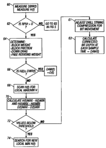
At 60 in Figure 4, a time-indexed record is made of the vertical position of
the hook, or vertical
position or top drive, represented by DBM(t), the hook load, represented by
H(t), the drill string
rotation rate, represented by RPM(t).
To calculate depth, in this embodiment, as shown at 64, the following values
are established
either by modeling, user input, or from measurements made by the sensors on
the drilling rig.
Modeling may include using a drilling engineering program sold under the trade
name
WELLPLAN by Landmark Graphics, Houston, TX. The values to be established may
include
the block weight (weight of the top drive or hook assembly), the free rotating
weight (the weight
of the drill string compensated for its buoyancy in the drilling mud), block
friction (friction force
needed to move the top drive up and down which may also be related to speed of
motion of the
top drive), block velocity (axial speed of motion of the top drive or hook
assembly), rotation
speed (RPM), and the down-drag forces (frictional force of axial motion
between the wellbore
wall and the drill string). The result of obtaining any or all of the
foregoing parameters is to
determine the expected hook load under the condition of the drill string
moving (rotationally
and/or axially) with normal friction within the wellbore. The expected
hookload under a rotating
condition is known as the "down weight rotating" (DWR).
The RPM sensor is interrogated, as shown at 62. If the drill string rotation
rate, RPM(t), is
greater than zero, the mode of drilling operations is determined to be
"rotating" or "rotary
drilling", and the calculation technique shown in Figure 4 continues. If the
drill pipe is not
rotating (RPM(t) equals zero), then the process will continue as will be
explained below with
respect to Figure 5.
The process accepts as input at the time of calculation (t), values of the
apparent bit depth D(t),
which is related to the top drive vertical position (block height) at time t
and an apparent
(uncorrected) axial length of the drill string. The input also includes the
measured hookload
H(t). As previously explained, these values are measured at 60.
When the drill string is moving downward in the wellbore and is rotating,
under the condition
that the hookload is greater than or equal to the expected hookload at the
time of measurement,
namely H(t) ? DWR(t), then the corrected bit depth, DAM(t), is set equal to
the apparent bit
depth, or, DAM(t) = D(t). This is shown at 66 in Figure 4.
13
CA 02603653 2007-10-19
At 66 in. Figure 4, for time intervals when H(t) is less than DWR(t), in this
embodiment the
values of H(t) are scanned within a selected number of time samples ahead of
the time of
measurement to determine local maximum and minimum values of H(t). The times
and
hookload values at which these local maximum and minimum values take place can
be identified
by H(t)max and H(t)min. This is shown at 68 in Figure 4. Then, as shown at 70
in Figure 4, the
difference in hookload values between the local minimum and subsequent maximum
hookload
values is determined:
H (t) max - H (t) min
The difference in hookload in the above equation is compared to a selected
threshold, as shown
at 72 in Figure 4. If the value is below the selected threshold, then the
minimum value, H(t)min is
not used in calculating drill string length compression correction factors,
and another minimum
value of hookload is searched, as shown at 74. The threshold will be related
to the changes in
weight on bit (axial force) applied by the drilling rig operator (driller)
during operation of the
drilling rig.
If the threshold is exceeded, the hookload values are scanned back from the
time of the minimum
hookload, H(t)111;,,, until a value of hookload is found which is greater than
or equal to the value
of the maximum hookload subsequent to the minimum hookload. A time interval is
determined
between the subsequent maximum hookload and the found, prior hookload. If the
time interval
is longer than a selected threshold, then another minimum value is searched
from the hookload
measurements. If the prior maximum is greater than the subsequent maximum,
then the next
smaller hookload value is used with the prior maximum to interpolate an
expected time at which
the hookload would be exactly the same as the subsequent maximum hookload
value. This time
can be referred to as the prior maximum hookload time (t)pmx. The apparent bit
depth at the
time of the prior maximum hookload value, referred to as D(t)p,,,, should also
be interpolated
from the time/apparent bit depth measurements. An apparent rate of penetration
at the time of
minimum hookload can then be determined by the expression:
ROP(t)min = (D(t)max - D(t) pmr) /(tmax - tp, )
Then, a value for drill string compression adjusted for bit movement at the
time of the minimum
hookload, K(t)m1 is then determined from the following equation:
14
CA 02603653 2007-10-19
(K(t) min
(D(t) min - D(t) pmc - (ROP(t) min x (tmin - tpmx ))) /(H(t) max - H (t) min )
The values of K(t),,11õ determined according to the above expression can then
be linearly
interpolated with respect to depth. This is shown at 61 in Figure 4.
L)AM(t) = D(t) - K(t) X (DWR(t) - H(t))
Correcting the bit depth is shown at 63 in Figure 4.
Going back to 64 in Figure 4, if the RPM is equal to zero, the drilling mode
is known as
"sliding." Sliding drilling, as is known in the art, is performed under
certain conditions using a
motor powered by the flow of drilling fluid disposed in the BHA. Such motors
are known in the
art as "mud motors."
If the drilling mode is sliding, a different expected hookload can be
determined, called DWR(t),
using a model, user input or drilling rig sensor data as described above with
respect to Figure 4.
Referring to Figure 5, when sliding, for intervals when the expected hookload
is equal to or
greater than the expected hookload when the drill string is axially sliding
down, the corrected bit
depth can be set equal to the apparent bit depth, just as in the previous
embodiment for rotary
drilling. This is shown generally at 67 and 69 in Figure 5. In intervals where
H(t) is less than
DWR(t), then the process continues substantially as explained above with
respect to rotary
drilling. At 71, H(t) values are scanned for local maxima and minima. Values
of rate of change
of hookload with respect to depth are calculated as shown at 73. At 75, an
amount of drill string
compression is adjusted with respect to rate of penetration at the drill bit,
and finally, at 77,
corrected values of depth, DAM(t), at each sample time are determined.
The corrected values of depth with respect to time, DAM(t), can then be then
used to re-compute
times when in on-bottom drilling modes as well as new ROP curves, logging
while drilling
(LWD) processed formation data, time-depth and depth-time transformations and
further
calculations such as drilling exponents (d-exponent), lithology and pore
pressure. Pore pressure,
in some embodiments, may be determined from the drilling exponent, as is well
known in the art.
Referring to Figure 6, another aspect of the invention relates to data
classification in order to
improve interpretation of selected data. A recording of each type of data made
in the recording
CA 02603653 2007-10-19
system (12 in Figure 1) at each time, t, may be referred to by the notation
f(t). A complete data
recording thus includes, at 96 in Figure 6, a value of various recorded
parameters corresponding
to each recording time. The recording may include values of parameters
measured by the
sensors at the earth's surface, including the top drive position sensor, hook
load sensor and the
torque sensor, for example. The recording may also include values of
parameters measured by
the various sensors in the MWD system (37 in Figure 1) which are communicated
by the mud
telemetry as previously explained. The recording may also include values of
parameters
recorded. in the MWD system (37 in Figure 1), and linked to the recording
system (12 in Figure
1) after the MWD system is removed from the wellbore. In still other
embodiments, the MWD
system may include a system for communicating signals representing sensor
measurements to
the earth's surface substantially in real time for recording by the recording
system. Such real
time communication may be performed where the segments of pipe (32 in Figure
1) include an
electromagnetically coupled signal line, such as disclosed in U.S. Patent
Application Publication
No. 20020075114 Al filed by Hall et al. The drill pipe disclosed in the Hall
et al. application
includes electromagnetically coupled wires in each drill pipe segment and a
number of signal
repeaters located at selected positions along the drill string for
communicating signals to the
earth's surface from an instrument disposed in a wellbore.
In a process according to this aspect of the invention, the data are
preferably categorized
according to at least one of the first difference of another measurement 4f(t)
(as explained more
fully below) a second difference of another measurement 44f(t) (as explained
more fully below),
the type of operation taking place on the drilling rig (10 in Figure 1) which
may be related to the
bit depth determined in the previous method (described with respect to Figures
4 and 5), the
mode of motion of the drill string as determined from the values of some
acceleration parameter
and an associated lithology, as determined by methods well known in the art.
In the present embodiment, at 98, for each value of parameter, f(t), a first
difference, 4f(t)
between each parameter value and the immediately previous parameter value may
be
determined. A value of a second difference, A(4f(t)), may also be determined
between the
current first difference value and a first difference value for the successive
measured parameter.
,V (t) = .f (t) - .f (t -1)
,A(Of(t))=Af(t+1)-Of(t)
16
CA 02603653 2007-10-19
In some embodiments, if the value of the first difference exceeds a pre-
selected threshold, shown
at 100 in Figure 6, then the measured parameter value at time t is not
assigned to the enhanced
data set and the representative value of f'(t) is set to a default value such
as zero or null. This is
shown generally at 116 in Figure 6. An example of a measured parameter that
can be
discriminated on the basis of the first difference is the velocity of motion
of the top drive (14 in
Figure 1). Another example of a parameter that can be discriminated using the
first difference is
the rotation rate of the drill string, RPM. First difference with respect to
depth of the formation
gamma-:ray signal measured downhole using the sensors in the MWD system (37 in
Figure 1),
that is transformed into the time domain using depth-time transforms known in
the art, may also
be used to discriminate data which are to be included in the enhanced data
set. Another example
of a parameter that can be discriminated on the basis of the first difference
is torque applied to
the drill string by the top drive and measured at the surface. First
difference of the torque
measured downhole using the sensors in the MWD system (37 in Figure 1) may
also be used to
discriminate data which are to be included in the enhanced data set. In some
embodiments, if
either the value of first difference and/or second difference exceeds pre-
selected thresholds, at
100 in Figure 6, then the current parameter values f(t) may be recorded as a
default value such as
zero or null in the enhanced data f'(t), as shown at 116 in Figure 6. It
should be understood that
the enhanced data type may be different than the data type used to determine
the first and second
differences. Examples of parameters that may be discriminated using the first
and second
differences include the vertical position of the top drive (also known as
"block height"), and
rotary orientation of the drill string, which may be measured at the surface
or using the sensors in
the MWD system (37 in Figure 1).
In some embodiments the data classification may be enhanced by determining the
drilling mode
of operation, using various drilling control parameters such as, but not
limited to, rotation rate of
the drill string (RPM), pump rate (flow), rate of penetration (ROP) and axial
velocity of the top
drive, shown generally at 102 in Figure 6. For example, by determining places
where the ROP is
non-zero and the RPM is greater than zero, the data may be classified as
recorded during "rotary
drilling". If ROP, as may be determined from the method represented in Figures
4 and 5, is zero
or the RPM is zero, in this example, the recorded data are not representative
of those recorded
during rotary drilling of the wellbore. At 104 in Figure 6, if the data are
classified as not being
17
CA 02603653 2007-10-19
recorded. during rotary drilling, then a value of the enhanced data at time t
for a parameter,
represented byf'(t), may be set to a default value such as zero or null, shown
at 116 in Figure 6.
In some embodiments, different drilling mode operations, for examples tripping
in, tripping out,
forward-reaming and back-reaming may be used to discriminate whether measured
data are, or
are not ultimately included in the enhanced data set.
Some embodiments for enhancing the quality of data used in subsequent
analyses, discriminate
data based upon the lithology associated with data at different time
intervals, for example the
lithology being drilled at time t, shown generally at 106 in Figure 6. Often
lithology is recorded
by formation sensors in the depth domain. A depth-time transformation, the
inverse of time-
depth transformations well known in the art, may be required in order to use
lithology for
discrimination of data in the time domain at any time t. At 108 in Figure 6,
if the data are
classified as not corresponding to a particular lithology, then the value at
time t of enhanced data
values fDr a parameter, represented by f'(t), may be set to a default value
such as zero or null,
shown at 116 in Figure 6.
Some embodiments of calculating an enhanced data set includes discriminating
the data as
measured with respect to whether or not the drill string is in a mode of
motion which dissipates
some of the drilling energy by transferring the energy into the drill string
and/or the side of the
wellbore, instead of transferring the drilling energy efficiently to the drill
bit. Examples of such
dissipative drilling modes include, without limitation, whirl, lateral
vibration, axial vibration,
shocks, stick slip and torsional vibrations. In the present embodiment, and
referring to Figure 6,
a parameter related to at least one of the following is measured: angular
acceleration; axial
acceleration and lateral acceleration. This is shown at 110 in Figure 6. Any
of these parameters
may be measured at the surface, or may be measured by various sensors in the
MWD system (37
in Figure 1). For example, vertical position of the top drive (14 in Figure 1)
may be measured
and doubly differentiated with respect to time to obtain the axial
acceleration of the drill string at
the earth's surface. Other embodiments may include an acceleration sensor or
strain gauge
coupled to the top drive or hook. Correspondingly, the acceleration along the
drill string axis
may be directly measured by the sensors in the MWD system (37 in Figure 1). As
another
example, torque may be measured at the earth's surface, and variations in the
measured torque
can be used as an indication of the angular acceleration of the drill string.
Alternatively, torque
18
CA 02603653 2007-10-19
and/or angular acceleration may be measured by the various sensors in the MWD
system (37 in
Figure 1). As another example, lateral acceleration of the drill string may be
measured by the
various sensors in the MWD system (37 in Figure 1).
At 112 in Figure 6, the measured parameter related to the one or more
accelerations is compared
to a selected threshold. The threshold value is related to which particular
acceleration-related
parameter is being measured. If, at 112, the parameter does not exceed the
selected threshold,
then the values of the sensor measurements at that point in time may be
included in the enhanced
data set, wherein f(t) = f(t), shown at 114 of Figure 6. If the acceleration-
related parameter
exceeds the selected threshold, at 112 of Figure 6, then the data values of
the enhanced data set
may be set to a default value, such as zero or null, as shown at 116 of Figure
6.
Examples of drilling and/or formation evaluation parameters that may be
discriminated (as to
whether included in an enhanced data set) using the foregoing embodiment
include, without
limitation, rotary speed of the drill string (RPM), mud pump rate (or mud flow
rate), standpipe
(drilling fluid) pressure, axial force on the bit (WOB) measured either at the
surface or
downhoie, rate of penetration (ROP) and torque applied to the drill string at
surface.
One purpose of selecting data for inclusion in a so-called "enhanced" data set
according to this
aspect of the invention is to identify data which are associated with
preferred drilling intervals
under preferred drilling conditions, so as to enhance interpretation made from
these selected
data. For example, formation density measurements made by the sensors in the
MWD system
(37 in Figure 1) in an enhanced data set may represent more closely the actual
earth formation
properties when a sensor is consistently in contact with or oriented towards
the formation being
measured. As another example, measurements of weight on bit, torque at the
bit, RPM of the bit
or rate of penetration may not be representative of the force required to
drill a particular
formation if there is a substantial amount of axial, angular and/or lateral
vibration in the drill
string. Accordingly, in one embodiment, the values of first and second
difference of values of
torque recorded at the surface and angular and/or axial and lateral
acceleration recorded in the
MWD system (37 in Figure 1) are compared to a selected threshold. Values of
first and/or
second difference which exceed the selected threshold indicate that the BHA
and/or drill string
are undergoing excessive vibration or are undergoing torsional "stick slip" or
"whirl" motion.
Data values recorded during intervals of such unfavorable (dissipative) drill
string motion may
19
CA 02603653 2007-10-19
be excluded from preferred interpretation techniques such as drilling exponent
and pore pressure
calculations known in the art.
One important application for generating a "preferred" data set as explained
above with respect
to Figure 6 is providing input data for training a neural network or fuzzy
logic algorithm adapted
to optimize and/or control drilling operating parameters and/or to affect
selection of hydraulic
(mud) motor and/or drill bit design parameters. Using the preferred data set
to train an artificial
neural network (ANN) is shown at 118 in Figure 6. Methods for training neural
networks to
control drilling operating parameters and bit design parameters are disclosed
in U.S. patent no.
6,424,919 B 1 issued to Moran et al. In embodiments of the present invention,
time-based values
of control parameters that are used to train a neural network to optimize
drilling performance
include weight on bit, drilling mud flow rate and rotary speed of the bit.
During training of the
neural network, values of the control parameters are recorded with respect to
the output
parameter. In some embodiments, for example, the output parameter may be cost
per unit depth
drilled. In other embodiments, for example, the output parameter may be rate
of penetration. In
other embodiments, the output parameter may be surface torque magnitude. In
embodiments of
the present invention, only data from the preferred data sets are used to
train the neural network.
Advantageously, embodiments of a method for training a neural network
according to the
invention may have reduced training time, and improved correlation between the
control
parameters and the output parameters because more reliable and representative
values of control
parameter are used.
One example of a process for controlling drilling operations using "enhanced"
data (for example,
characterized according to the example process shown in Figure 6) is shown in
Figure 7. In
Figure 7, at 120, drilling operating parameters, and drilling response
parameters can be
correlated to the depth in the wellbore at which each parameter is recorded
with respect to time.
Examples of drilling operating parameters include, without limitation, weight
on bit, drilling
fluid flow rate, and rotating rate of the drill string (RPM). The foregoing
are referred to as
drilling operating parameters because they are within the direct control of,
and are selected by
the drilling rig operator. Drilling response parameters include, for example,
rate of penetration,
torque, and accelerations (axial, torsional, lateral and/or whirling)
experienced by various
components of the drill string. The foregoing are referred to as response
parameters because
CA 02603653 2007-10-19
they are a result of the drilling operating parameters, the configuration of
the drill string and the
earth formations being drilled, among other factors, and are therefore
typically not under direct
control of the drilling rig operator. It should be noted that some drilling
rigs have equipment
adapted to enable the drilling rig operator to select the torque applied to
the drill string at the
surface. On such drilling rigs, surface torque may in fact be a drilling
operating or control
parameter.
At 122 in Figure 7, data corresponding to the composition and the mechanical
properties of the
various earth formations penetrated by the wellbore are entered into a
correlation program.
Typically, data corresponding to the composition and mechanical properties of
the earth
formations ("lithology" data) are recorded with respect to depth in the
wellbore if they are
recorded using so-called "wireline" well logging instruments. In order to use
depth referenced
data for purposes of controlling drilling operations, it is convenient to, and
in the present
embodiment, at 124, the lithology data are converted from depth-referenced
records, to time at
which the measurements of the various drilling parameters were made. Thus
referenced with
respect to time, the composition and mechanical property data can be indexed
to the drilling
operating parameters and drilling response parameters corresponding to the
time of drilling
through the respective formation. Conversion from depth reference to time
reference thus makes
subsequent use of the lithology data more effective in analysis used to
control drilling operations
that will be further explained below. Examples of data which may be used to
characterize the
earth formations according to composition and mechanical properties
(lithology) include,
without limitation, drill cuttings description, drilling exponent, formation
hardness, electrical
resistivity, natural gamma radiation, neutron porosity, bulk density, and
acoustic interval travel
time.
It should be noted that changing the reference index of lithology data from
depth to time may
require some interpolation of data values between recorded values. Methods for
interpolation are
well known in the art and include linear and cubic spline. The actual form of
interpolation is not
intended. to limit the scope of the invention. It should also be understood
that lithology data may
be recorded during drilling of the wellbore using well known MWD sensors. MWD
data are
typically recorded with respect to time, however the recording rates may
differ from the
measurement sample and recording rate of the sensors disposed at the earth's
surface and
21
CA 02603653 2007-10-19
measurements from different sensors recorded at any one time relate to
formations at different
offset depths. Therefore, MWD formation data need to be correlated in the
depth domain, then
transformed back into the time domain and re-sampled to have a data record
"density" (samples
per unit time) substantially the same as the drilling data recorded either
downhole or at the
earth's surface.
At 126 in Figure 7, "enhancement" characterization of the drilling operating
parameters, drilling
response parameters and lithology data is performed, for example as explained
above with
reference to Figure 6, to determine whether the data are likely to be reliable
for subsequent
analysis. Data corresponding to times at which the drill string underwent
excessive acceleration,
or data which changed to an excessive degree from one sample interval to the
next, may be
excluded from further processing, as shown at 128. Data which are recorded
during times of
relatively difference-free and/or acceleration-free drill string motion are
selected for further
processing.
In the present embodiment, at 130 in Figure 7, data recorded during times at
which the drilling
operation is "slide drilling" can be separated from data recorded during times
at which the data
are "rotary drilling." To separate data accordingly, it is necessary to
determine the state of
drilling rig operations at the time of data recording as is well known in the
art. One example
process for determining drilling rig operating state is shown in Figure 6A. To
perform the
process in Figure 6A, certain parameters are measured, such as bit position
(hook position), the
maximum wellbore depth, the hook load, the operating rate of the drilling mud
pumps
(measurable either by a "stroke counter" known in then art or by measuring
drill string pressure),
and the rotary speed (RPM) of the top drive (or rotary table). At 190 the
process begins. For
example, at 192, a Boolean logic routine queries whether the mud pumps have
more than zero
operating rate or output pressure. If not, and the bit position is changing
(as a result of hook
movement or change in hook load), the bit position is less than the total
wellbore depth and the
drill string is not rotating (RPM=O), the drilling mode is determined to be
tripping pipe in or
tripping pipe out (removing or inserting the drill string into the wellbore),
at 194. As another
example, if the mud pump has non-zero output, at 196, the routine queries
whether the change in
bit depth is greater than zero with respect to time, the bit depth is less
than the hole depth and the
drill string is not rotating. If, with these additional conditions, the bit
position is not changing, at
22
CA 02603653 2007-10-19
198, the mode is determined to be circulating. Another example is when the bit
position is
increasing or constant with the mud pump pressure greater than zero and bit
position equal to the
total wellbore depth. Under these conditions, at 204, the rotary top drive
speed is interrogated.
If the speed is greater than zero, at 208, the mode is rotary drilling. If the
rotary speed is zero, at
206, then the mode is slide drilling. Another example is when the measured
hookload is
substantially equal to the weight of the top drive, the mud pump pressure
(measured by
transducer 28 in Figure 1) is zero and the RPM is zero, with the bit position
less than the
wellbore depth. Under these conditions the drilling mode is determined to be
"in slips" during
such operations as adding additional length to the drill string. The foregoing
are only some
examples of determining drilling mode by interrogating selected data values.
For purposes of
this aspect of the invention, the important drilling rig operating modes are
slide drilling and
rotary drilling.
Referring back to Figure 7, at 132, the combinations of drilling response
parameters and drilling
operating parameters are characterized with respect to a most likely lithology
or formation
property. Determining the most likely lithology or formation property for
combinations of
drilling operating parameters and drilling response parameters may be
performed, for example,
by using an artificial neural network, Bayesian network, regression analysis,
error function
analysis., or other methods known in the art for characterization. As a
result, measuring
particular drilling responses for particular drilling operating parameters may
provide the ability
to determine the lithology only from the measured drilling operating
parameters and drilling
response parameters. Drilling response, as previously explained, may include
rate of penetration,
drill string torque and acceleration (lateral, torsional, axial and/or
whirling) of the drill string, as
previously explained. At 134, the drilling data are then characterized
according to the various
types of formations penetrated during drilling as determined from formation
data sources well
known in the art such as, but not limited to, "wireline" well log
measurements, analysis
(lithological description) of drill cuttings returned to the earth's surface
through the drilling fluid,
core sarriples drilled through the various formations and/or MWD formation
evaluation sensor
data. The drilling data are separated according to groups of drilling mode and
similar
composition and/or mechanical properties. As will be appreciated by those
skilled in the art,
such separation may include separation into groups having typical earth
formation compositions
23
CA 02603653 2007-10-19
associated with wellbore drilling, such as "hard formation", "soft formation",
"shale",
"sandstone", "limestone" and "dolomite." The foregoing classifications are
merely examples
and are not intended to limit the classification of the various lithologies
used in any particular
embodiment of a method according to this aspect of the invention.
At 136, a preferred set of drilling operating parameters is determined for
each lithology. A
preferred set of drilling operating parameters may be determined, for example,
when a rate of
penetration is at a maximum and amounts of lateral, axial, torsional and
whirling acceleration of
the drill string are at a minimum, for each lithology. Determining preferred
drilling operating
parameters may be performed, for example, by using an artificial neural
network, Bayesian
network, regression analysis, error function analysis, or other methods known
in the art for
optimization.
At 138, during actual drilling of a wellbore, measurements of drilling
operating parameters and
drilling response parameters are made. At 140, the drilling operating
parameter measurements,
and drilling response parameter measurements are characterized, such as
explained above with
respect to Figure 6. If the measurements fall outside the selection criteria
used to determined
enhanced data, as shown at 142, the values of the drilling operating
parameters extant at the time
of the characterization may be maintained. If the drilling measurements are
such that the
enhanced data set selection criteria are met, then the process continues. At
144, the drilling
operating mode (sliding or rotating) is determined. At 146, a most likely
lithology is determined
from the drilling operating parameters and the drilling response parameters.
At 148, a preferred
set of drilling operating parameters is applied to control the drilling rig
(10 in Figure 1)
according to the lithology determined at 146.
Figure 8 shows an example of using drilling response measurements, lithology
characterization
and drilling operating parameter measurements to predict drilling response.
Predicted drilling
response can be compared to actual drilling response to determine a drilling
malfunction. The
graph in. Figure 8 shows a measured rate of penetration, at curve 150. Curve
152 represents a
rate of penetration curve developed by a trained artificial neural network
(ANN). As shown in
the upper part of Figure 8, the ANN may be trained by entering drilling
operating parameters,
such as weight on bit 156 and rotary torque 158. Other drilling operating
parameters may
include RPM and drilling mud flow rate, for example. As is known in the art,
weighting factors
24
CA 02603653 2007-10-19
in the hidden layer 160 of the ANN adjust such that a response output, in this
example rate of
penetration 162 most closely matches the actual response for the particular
set of input
parameters to the ANN, in this example weight 156 and torque 158.
At curve 154 in Figure 8, a predicted drilling response is then generated from
the trained ANN
for inputs comprising drilling operating parameters. The actual drilling
response 150 is
compared to the predicted drilling response. Intervals, such as shown at 164,
in which there is
substantial difference between the predicted drilling response and the
measured drilling response,
may be indicative of a drilling malfunction. Examples of drilling malfunctions
include, without
limitation, a worn drill bit, a worn or broken drill string component,
unexpected lithology
change, and unexpected drill string acceleration. In some embodiments,
indications of a drilling
malfunction may be used to provide an alarm or other indication to the
drilling rig operator or
wellbore operator of the malfunction.
Embodiments of a system and methods according to the various aspects of the
invention may
provide improved time to depth correlation, improved accuracy in bit and
wellbore depth
determination, improved determination of rates of drilling penetration and
parameters related
thereto, improved selection of drilling operating parameters from enhanced
drilling data and
improved detection of drilling malfunctions from enhanced drilling data.
All of the foregoing embodiments of the invention, as well as other
embodiments, may be
implemented as logic instructions to operate a programmable computer. The
logic instructions
may be stored in any form of computer readable medium known in the art.
While the invention has been described with respect to a limited number of
embodiments, those
skilled in the art, having benefit of this disclosure, will appreciate that
other embodiments can be
devised which do not depart from the scope of the invention as disclosed
herein. Accordingly,
the scope of the invention should be limited only by the attached claims.