Note: Descriptions are shown in the official language in which they were submitted.
CA 02603707 2007-09-28
TCO2-107US
PATENT
1
MEDICAL ELECTRODE
TECHNICAL FIELD
The present invention relates generally to medical electrodes and, more
particularly, to disposable medical electrodes intended for high-energy
stimulation,
such as defibrillation.
BACKGROUND OF THE INVENTION
Medical electrodes provide an electrical interface between a patient and
monitoring equipment (e.g., an electrocardiograph device) or between a patient
and
stimulating equipment (e.g., interferential and iontophoresis devices). A
specific type
of stimulating electrode, used to provide an electrical interface between a
patient and
defibrillation equipment, must be capable of conducting the high-energy level
required
for transcutaneous defibrillation.
In a malady called "fibrillation," the normal contractions of a muscle are
replaced by rapid, irregular twitchings of muscular fibers (or fibrils).
Fibrillation
commonly occurs in the atria or ventricles of the heart muscle; the normal,
rhythmical
contractions of the heart are replaced by rapid, irregular twitchings of the
muscular
heart wall. A remedy for fibrillation is called "defibrillation," a procedure
which applies
an electric shock to arrest the fibrillation of the cardiac muscle (atrial or
ventricular)
and restore the normal heart rhythm.
Defibrillation electrodes deliver high-energy levels required for
defibrillation, up
to 360 Joules or more. Defibrillation electrodes also distribute the energy
over a
relatively large area of the epidermis of the patient to achieve adequate
current
density distribution within the atria or ventricles. Well-defined industry
standards exist
for defibrillation electrodes. In particular, the American National Standards
Institute
(ANSI) standards for defibrillation electrodes have been published by the
Association
for the Advancement of Medical Instrumentation (AAMI). The ANSI standards for
the
CA 02603707 2014-11-13
2
size of defibrillation electrodes recommend, for example, that the minimum
active
area of individual, self-adhesive electrodes used for adult defibrillation and
pacing
shall be at least 50 cm2 and that the total area of the two electrodes shall
be at least
150 cm2.
The specification for defibrillation recovery characteristics, which describes
certain time-related, electrical dissipation properties of the electrode
following
repeated electrical shocks of defibrillation currents, is difficult for many
electrodes to
meet. The use of non-compliant electrode may result in life-threatening delays
following defibrillation. This restriction limits the usefulness of such
electrodes in a
critical care environment. Accordingly, many of these products bear a caution
label
that they are not to be used where defibrillation is a possibility.
Irritation and burning of the patient's skin due to high current density
around
the perimeter of the electrodes and uneven current distribution is a common
problem with defibrillation electrodes, particularly after application of
repeated high-
level defibrillation or cardiac pacing pulses. A new disposable medical
electrode,
particularly useful for high-energy applications, is disclosed here. The
invention
provides an electrode that features control of current distribution. In
addition, the
electrode provides energy sufficient for defibrillation, and which has
improved
current distribution between the electrode and the skin surface of the patient
to
efficiently deliver the energy without burning the patient's skin.
SUMMARY OF THE INVENTION
In one embodiment the electrode comprises an electrically conductive
electrode member with a top face and a bottom face. A pattern of disconnected
regions of electrically conductive material is disposed on at least a portion
of the top
face of the electrode member. An electrical connector contacts the
discontinuous
pattern for delivering energy to and transmitting energy from the electrode. A
patient contacting layer is disposed on at least a major portion of the bottom
face of
the electrode member. An electrically conductive coating may cover at least a
portion of the bottom face of the electrode member, between the electrode
member
and the hydrogel.
CA 02603707 2014-11-13
2a
According to an aspect, there is provided a medical electrode comprising: an
electrode member having a top face and a bottom face; disconnected regions of
electrically conductive material in electrical contact with the top face of
the electrode
member; a patient contacting layer disposed on at least a portion of the
bottom face
of the electrode member; and an electrical connector in electrical contact
with the
disconnected regions of electrically conductive material.
According to another aspect, there is provided a method for fabricating a
disposable medical electrode configured for high-energy applications, the
method
comprising the steps of: obtaining an electrode member with a top face and a
bottom face; forming disconnected regions of electrically conductive material
on the
top face of the electrode member; adhering a patient contacting layer to the
electrode member; and securing an electrical connector in contact with the
disconnected regions of electrically conductive material.
Both the foregoing general description and the following detailed description
are exemplary, but are not restrictive, of the invention.
CA 02603707 2007-09-28
TCO2-107US
PATENT
3
BRIEF DESCRIPTION OF THE DRAWINGS
The invention is best understood from the following detailed description when
read in connection with the accompanying drawings. It is emphasized that,
according
to common practice, the various features of the drawing are not to scale. On
the
contrary, the dimensions of the various features are arbitrarily expanded or
reduced
for clarity. Included in the drawings are the following figures:
Fig. 1 is a perspective exploded view illustrating the components of a medical
electrode according to a first embodiment.
Fig. 2 is a perspective exploded view illustrating the components of a medical
electrode according to a second embodiment with an impedance gradient.
Fig. 3 shows plan views of eight examples of patterns of disconnected regions.
DETAILED DESCRIPTION OF THE INVENTION
Referring now to the drawing, wherein like reference numbers refer to like
elements throughout, the various embodiments of the present invention will be
explained in detail.
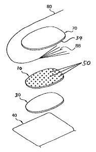
As illustrated in Fig. 1, the electrode has a release carrier sheet 40.
Release
carrier sheet 40 covers and protects a patient contacting layer 30, which may
comprise an electrically conductive gel layer, a gel pad containing
electrically
conductive gel, or an electrically conductive adhesive. The release carrier
sheet 40
may be made, for example, of silicone-coated polyethylene terephthalate (PET).
Although not required, a rectangular shape is suitable for the release carrier
sheet 40.
If rectangular as illustrated, dimensions such as a length of about 140 mm and
a
width of about 82 mm are suitable.
In one embodiment, the patient contacting layer 30 comprises a pad of
electrically conductive gel in contact with the release cover sheet 40 prior
to the use of
the electrode. The gel pad may be approximately 65 mm wide and 122 mm long.
The
gel pad may comprise a skin compatible conductive hydrogel or adhesive having
good
ability to retain moisture content and adhesive tack. Examples of suitable
hydrogels
include conductive hydrogels commercially available from the Kendall-LTP
division of
Tyco Healthcare Group LP, Mansfield, Massachusetts, such as RG-63B conductive
hydrogel.
Patient contacting layer 30 is in electrical contact with electrode member 10.
In a second embodiment, shown in Fig. 2, the medical electrode may further
comprise
CA 02603707 2007-09-28
TCO2-107US
PATENT
4
a conductive coating 20 in contact with at least a portion of the bottom face
of
electrode member 10. One specific example of conductive coating 20 is a
silver/silver
chloride ink coating. The conductive coating may have a variation or gradient
in
coverage - and hence in impedance - from center to edge in order to further
reduce
current density which can result in skin irritation or burning. As one
example,
disclosed in detail in US Patent 6,600,957 and shown in Fig. 2, the ink
coverage is
100% in the area from the center of coating 20 to an inner edge 24. In the
area
between inner edge 24 and an outer edge 26, the percentage decreases linearly,
reaching zero at the outer edge 26.
An impedance gradient may also be formed with a two-layer conductive
coating. A conductive coating, such as silver/silver chloride, may be applied
to a
bottom face of electrode member 10, with the outer perimeter of the coating
spaced
inwardly from the perimeter of the electrode member 10. The coating may be
formed
in two layers each of a few microns in thickness with a first layer having an
outer
perimeter spaced inwardly of the perimeter of the electrode member 10 and a
second
layer having an outer perimeter spaced inwardly from the perimeter of the
first layer.
The two layers may be applied successively on electrode member 10 to allow the
first
layer to dry before applying the second. The second layer may be applied first
with
the first layer underlying the second layer. The dual layers provide higher
electrical
conductivity in the area where the layers overlap, with the conductivity
stepping down
in the single layer and decreasing to the conductivity of a carbon filled
polymer of the
electrode member 10 in the area outwardly of the coating. The area where the
layers
overlap, which corresponds to the area of the first layer, may be made
substantially
equal to the minimum active electrode area prescribed by ANSI/AAMI. For
example,
the two layers can each have a thickness of about 3 to 5 microns, with a
combined
thickness in the area of overlap of about six to ten microns. In addition, the
outer
perimeter of the two layers are advantageously serrated or undulated. This
arrangement further decreases the current density by increasing the effective
perimeter of the electrode member and, in combination with the use of
disconnected
conductive regions 50, minimizes the likelihood of skin burns or irritation.
The electrode member 10 may be formed of a thin, flexible sheet of
electrically
conductive polymer film such as graphite-filled polyvinyl chloride film. The
film may
also contain carbon black, acetylene black, or other forms of carbon. An
example of
CA 02603707 2007-09-28
TCO2-107US
PATENT
carbon filled polymer which can be used is commercially available thin carbon
filled
polyvinyl chloride (PVC).
A pattern of disconnected regions of electrically conductive material 50 is in
contact with the top face of the electrode member 10. The pattern may comprise
separated, disconnected regions of an electrically conductive material 50,
such as a
conductive ink. The regions 50 may have the shape of stripes, filled polygons,
unfilled
polygons, filled closed curves, concentric closed curves, unfilled closed
curves, letters,
logos, and any combination thereof. Examples of such patterns of disconnected
regions 50 are shown in Fig. 3. In the embodiment shown in Fig. 1 the pattern
is
made up of regions of electrically conductive material 50 in the shape of a
cruciform or
crossed lines, similar to the letter "x". The pattern may cover essentially
the entire
top face of the electrode member 10, as in the embodiment shown in Fig. 1.
The disconnected regions of electrically conductive material may be formed by
printing the electrically conducting material in a discontinuous pattern.
Alternatively,
the regions may be formed by forming a sheet comprising an electrically
conductive
material and printing a pattern of electrically non-conducting material on the
sheet.
The regions not covered by the non-conducting material form the disconnected
regions
of electrically conductive material. The sheet may then be laminated to the
top face of
the electrode member 10 to complete the formation of regions 50. As a specific
example, forming the sheet of electrically conductive material may comprise
flood-
coating the top face of electrode member 10 with an electrically conductive
fluid, such
as a silver/silver chloride ink, and allowing the fluid to dry or otherwise
solidify.
An electrical connector 88 is situated in direct contact with the disconnected
pattern of electrically conducting material 50. The electrical connector 88 is
connected
to a conductor which together function to convey electrical signals between
the
electrode and an apparatus (not shown) such as a defibrillator or
electrocardiograph.
In the embodiment shown in Fig. 1 the connector 88 is a fanned wire. Another
suitable connector may be a metal foil fanned in a similar manner to that of
connector
88 in Fig. 1. Other suitable connectors include snaps, rivets, or metal foils
well known
in the art.
The connector 88 is kept in physical and electrical contact with the
disconnected conductive regions 50, and hence with the electrode member 10, by
sandwiching it with a cover sheet 70 which is adhered to the top face of the
electrode
member 10 with an adhesive layer 34. The adhesive layer 34 may be a pressure
CA 02603707 2007-09-28
TCO2-107US
PATENT
6
sensitive adhesive. The cover sheet 70 may be a continuous foam backing sheet
without any openings and having a thickness of about 1 mm. In the embodiment
shown in Fig. 1, cover sheet 70 extends to the outer dimensions of gel pad 30.
Thus,
the cover sheet 70 and the gel pad 30 form a single peripheral edge for the
electrode
once release carrier sheet 40 is removed. In an alternate embodiment, adhesive
34
may be used to additionally secure connector 88 to electrode member 10.
Adhesive
34 may comprise a conductive or non-conductive material. By way of example,
adhesive 34 may be applied in a stripe across a fanned wire as shown in Fig.
1.
Suitable conductive adhesives include hydrogels and epoxies. Suitable non-
conductive
adhesives include pressure sensitive adhesives.
In the embodiment shown in Fig. 1 the electrode member 10 and the
disconnected regions 50 lie essentially in a plane, and connector 88 is held
in contact
with disconnected conductive regions 50 by cover sheet 70. In an alternate
embodiment, electrode member 10, with disconnected conductive regions 50, may
be
folded over connector 88, thereby enclosing connector 88 and maintaining its
contact
with conducting regions 50.
Within the pattern of disconnected regions 50, the shapes and sizes of regions
and spaces between the regions may be chosen so as to achieve a distribution
of
electrical current in the electrode which optimizes the electrode impedance
for a given
application, while also minimizing the effects of high current concentration
in some
regions of the electrode which could result in patient skin irritation and
burning. By
way of example, if the sizes of each of the disconnected regions 50 are too
small, or
their density (number of regions per unit area) is too small, the electrical
impedance
of the electrode may be unacceptably high due to insufficient metal-to-metal
contact
between the connector 88 and the disconnected conductive regions 50.
Conversely, if
the regions 50 are too large or too dense, the electrical impedance of the
electrode
may result in burning or irritation of the patient's skin. It follows that
there is a
desired range of patterns (region sizes and densities) that minimize patient
skin
irritation and burning, while achieving optimal values of overall impedance.
In some applications it is desirable that connector 88 be X-ray transmissive.
X-ray transmissive conductors may be formed of metallized carbon fiber tows
with an
insulating sheath formed of an X-ray transparent material. The carbon fiber
tows may
be of a size having between 3,000 to 12,000 fibers and metal plated with a
metal
coating that is about 20% to 50% by weight of the metal plated carbon fiber
tow. The
CA 02603707 2014-11-13
7
higher weight plating on the larger size tows provides improved current
carrying
capacity for repeated defibrillation pulses. Fiber tows may be made from a
polyacrylonitrile precursor and are referred to as pan base carbon fiber and
are
commercially available from Amoco Performance Products, Inc., Atlanta, Ga.
Since
the density of the carbon fiber tows is very low as compared to the density of
the
metal coating, a metal coating of 30% to 40% by weight of the metal plated
carbon
fiber tow is very thin and is X-ray transparent. The metal coating may be
nickel
which provides good electrical conductivity and corrosion resistance at
moderate
cost, but other metals such as copper or silver or gold could be used alone or
in
combination with the nickel coating.
In electrode applications where X-ray translucency of the connector 88 is not
required, the connector 88 can be formed of metal such as copper, tin, silver,
or
gold. For example, a fanned wire, such as that shown in Fig. 2, may be formed
of
multi-strand conductors which can be spread out to increase the contact area
between the connector 88 and the disconnected regions 50. When metal fanned
wire is used, the rest of the electrode remains x-ray transmissive with only
the
metal fanned wire visible on the x-rays.
Although the invention is illustrated and described herein with reference to
specific embodiments, the invention is not intended to be limited to the
details
shown. Rather, various modifications may be made in the details within the
scope
and range of equivalents of the claims and without departing from the
invention.
Although the invention is illustrated and described herein with reference to
specific embodiments, the invention is not intended to be limited to the
details
shown. Rather, various modifications may be made. The invention is defined by
the
claims.