Note: Descriptions are shown in the official language in which they were submitted.
CA 02603872 2007-10-03
WO 2006/110145 PCT/US2005/012426
-1-
METHOD OF AND APPARATUS FOR STRENGTHENING EDGES
OF ONE OR MORE GLASS SHEETS
BACKGROUND OF THE INVENTION
1. Field of the Invention
This invention relates to a method of and an apparatus for
cooling edge portions, e.g. peripheral and marginal edge portions, of one or
more sheets, e.g. one or more glass sheets, to strengthen the edge portions
of the sheets, and in particular, to method of and apparatus for extracting
heat
at a faster rate from edge portions of heated glass sheets supported on a
bending iron than the central portions of the sheets to rapidly cool and
strengthen the edge portions of the sheets.
2. Discussion of Technical Background
The method of laminating glass windows for vehicles, e.g.
automotive windshields, usually includes the steps of forming the glass
sheets, e.g. by placing a pair of glass sheets onto a mold commonly referred
to as one of the following: a bending iron, a bending mold, a shaping mold
and an outline mold, and moving the outline mold and glass sheets supported
thereon through a heating furnace for gradual heating and gravity sagging of
the pair of glass sheets to provide glass sheets having a desired shape. After
the sheets are shaped, the sheets are slowly cooled during an annealing
cycle to remove most of the stress from the glass sheets. Edge compression
for such glass sheets is normally about 1500 to 2500 pounds per square inch
("psi") (10.3 to 17.3 x 10⁶ Pascals ("Pa")). After the shaping and annealing
operations, a sheet of polyvinyl butyral is placed between the glass sheets to
provide a subassembly which is exposed to heat and pressure during a
conventional laminating process to form a laminated glass window, e.g. a
laminated automotive windshield.
It is generally understood that edge compression of less than
about 1500 psi (10.3 x 10⁶ Pa) increases the probability of damaging the
CA 02603872 2007-10-03
WO 2006/110145 PCT/US2005/012426
-2-
edges of a laminated glass window, e.g. a laminated windshield during
installation into a vehicle window opening. As can be appreciated, increasing
the edge compression to at least 3000 psi, e.g. 3,000 - 5,000 psi (20.7 -
34.5 x 10⁶ Pa) reduces the tendency of edge damage, e.g. during installation
of the windshield.
U. S. Patent No. ("USPN") 5,938,810 discusses press-bending
sheets utilizing forced area cooling. In general, a sheet of glass is heated
to a
formable state and pressed between a rigid mold and pressing member. The
pressing member presses the heated sheet against the rigid mold to bend and
cool the sheet. USPN 5,938,810 recognizes that in some applications, for
instance in windshields, it is desirable to cool the edge of the glass sheet
at a
faster rate than the central portion of the sheet to provide an enhanced edge
temper on the glass sheet. The cooling of the glass edges is accomplished
by using an internal air_manifold that directs'.air to the edge of a heated
glass
sheet while the sheet is between the- tigid-.mold and the pressing member.
USPN's 4,749,399; 5, 6791:124.:and.6,015,619 also discuss
techniques of cooling marginal edge portions of.glass sheets supported on
cooling rings to strengthen the edges of glass sheets.
Although there are techniques to cool the edges of a glass sheet
while the sheet is between pressing molds, and to cool the marginal edges of
a glass sheet while on a cooling ring; there are no satisfactory techniques to
cool the peripheral edges of a pair of shaped glass sheets while supported on
an outline mold, e.g. but not limited to outline molds, and/or shaping
techniques, of the types discussed in USPN's 3,976,462; 4,375,978;
4,687,501; 4,894,080; 4,979,977 and 5,049,178.
As can be appreciated, it would be advantageous to provide a
method of and apparatus for extracting heat at a faster rate from the
peripheral and marginal edge portions of heated glass sheets supported on
an outline mold than the central portions of the sheets to cool and strengthen
at least the peripheral edge portions of the glass sheets.
CA 02603872 2007-10-03
WO 2006/110145 PCT/US2005/012426
-3-
SUMMARY OF THE INVENTION
The present invention provides a furnace comprising: a section
defined as a heating section capable of attaining a predetermined
temperature, the heating section having an entrance end and an exit end; a
section defined as a cooling section capable of having a temperature gradient
from entrance end of the cooling section to exit end of the cooling section,
the
entrance end of the cooling section mounted in a fixed relationship to the
exit
end of the heating section; a section defined as an edge cooling section
between the exit end of the heating section and the entrance end of the
cooling section; and an edge cooling device positioned in the edge cooling
section relative to a predetermined area, and capable of cooling at least
selected peripheral portions of the predetermined area at a faster rate than
center portions of the predetermined area. Although not required, the furnace
can include a conveying arrangement to move ,a glass sheet through the
- heating section, into the_ predetermined area of the-.edge cooling section,
wherein at least peripheral portions of the sheet. are:icooled: faster than
center
portions of the sheet, and through the cooling section,:wherein the cooling
section has a temperature gradient to provide the glass sheet within one of
the following categories; an annealed sheet, a tempered sheet and a heat
strengthened sheet. In nonlimiting embodiments of the invention, the edge
cooling device is selected from equipment for directing fluid toward the
predetermined area, equipment for providing a negative pressure to the
predetermined area and equipment for absorbing radiant energy from the
predetermined area.
The present invention also provided a method of strengthening
at least the peripheral edge portions of at least one sheet, the at least one
sheet having opposite major surfaces and a peripheral edge between and
interconnecting the opposite major surfaces, the method comprising: heating
the at least one sheet to a temperature above strain point of the sheet;
positioning a heat-extracting medium in facing relation to selected peripheral
edge portions of the at least one sheet; extracting heat from at least
selected
CA 02603872 2007-10-03
WO 2006/110145 PCT/US2005/012426
-4-
peripheral edge portions of the at least one sheet while having a center
portion of at least one of the major surfaces of the at least one sheet out of
contact with any solid object, wherein heat is extracted from the at least
selected peripheral edge portions of the at least one sheet,at a rate
sufficient
to increase the edge strength of the at least selected peripheral edge
portions
and adjacent marginal edge portions of the at least one sheet and to establish
a temperature differential between the peripheral edge portions of the at
least
one sheet and the center portion of the at least one sheet to prevent
fracturing
of the at least one sheet during the practice of extracting heat. In
nonlimiting
embodiments of the invention, the cooling step is selected from one of the
following steps: annealing the shaped glass sheets, heat strengthening the
shaped glass sheets and tempering the shaped glass sheets.
In another embodiment of the present invention involving a
method of making a windshield by heating and shaping a: pair of glass sheets
while supported on an outline mold,,rannealing the shaped-sheets placing a
plastic interlayer between the shaped glass sheets, and:.autoclaving the
shaped glass sheets having the plastic interlayer therebetween:to laminate
the shaped glass sheets and plastic interlayer together, the methods includes
an improvement comprising: after the practice of heating and shaping, :
extracting heat from at least selected peripheral edge portions of the sheets
while supported on the outline mold at a rate sufficient to increase edge
strength of the at least selected peripheral edge portions and adjacent
marginal edge portions of the sheets and to establish a temperature
differential between the at least selected peripheral edge portions of the
sheets and center portions of the sheets to prevent fracturing of one or both
of
the sheets during the practice of extracting heat.
The present invention further provides a glass sheet having an
annealed center portion and a peripheral edge, wherein portions of the glass
sheet within a distance of 0.125 inch (0.32 cm) from the peripheral edge have
a strength of at least 3,000 psi (20.7 x 10⁶ Pa). Although not required, the
glass sheet is part of a transparency selected from transparencies for above
CA 02603872 2007-10-03
WO 2006/110145 PCT/US2005/012426
-5-
water, below water, air and/or space vehicles; automotive side windows,
automotive back windows, multiple glazed windows for homes, buildings and
temperature controlled storage compartments having a viewing area.
BRIEF DESCRIPTION OF THE DRAWING
Fig. 1 is an isometric view of a nonlimiting outline mold or
bending iron that can be used in the practice of the invention.
Fig. 2 is a plan view of the interior of a nonlimiting embodiment
of a lehr that can be used in the practice of the invention to shape a pair of
glass sheets, edge strengthen the edge portions of the sheets in accordance
to the invention and anneal the edge strengthened shaped sheets.
Fig. 3 is a side elevated view of a pair of shaped glass sheets on
a nonlimiting embodiment of an outline mold or bending iron having
equipment incorporating features of the invention..to extract heat from at
Ieast
15' the peripheral edges of the shaped sheets'in:accor.dance to the invention:
Fig. 4 is a plan view of the. interior of, a nonlimiting.embodiment
of a furnace that can be used in the practice of the invention to shape'a pair
of
glass sheets, edge strengthen the edge portions of the sheets in accordance
to the invention and anneal the edge strengthened shaped sheets.
Fig. 5 is a plane view of a heat extracting member incorporating
features of the invention positioned about the peripheral edges of glass
sheets to strengthen the edges of the glass sheets in accordance to the
teachings of the invention.
Fig. 6 is a fragmented side elevated view of a nonlimiting
embodiment of a member for extracting heat from the edges of glass sheets
in accordance to the teachings of the invention.
Fig. 7 is a view similar to the view of Fig. 5 of a nonlimiting
embodiment of the invention for zone strengthening edge portions of glass
sheets.
CA 02603872 2007-10-03
WO 2006/110145 PCT/US2005/012426
-6-
DETAILED DESCRIPTION OF THE INVENTION
In the following discussion of nonlimiting embodiments of the
invention, heat is extracted or removed from at least the peripheral edges of
a
pair of shaped glass sheets supported on an outline mold, also referred to as
a bending iron, bending mold, or shaping mold, to cool the peripheral and
marginal edges of the glass sheets during the end of a shaping cycle or
process, and/or the start of an annealing cycle or process, at a faster rate
than the central portion of the glass sheets to strengthen at least the
peripheral edge portions of the sheets. The shaped glass sheets are
subsequently processed, e.g. laminated in any usual manner to manufacture
automotive windshields. As will be appreciated, the invention is not limited
to
the number of sheets that can have their edge portions cooled and
strengthened at one time, e.g. but not limiting the:invention thereto, the
edge
:portions of one, two, three or more sheets can be'cooled and strengthened~at
---one:time. Further, the invention is not limited-to:.theirnaterials, of the
glass ,.:f.. ..: :
sheets; e.g. but not limiting the invention thereto, the edges portions of
plastic
metal,. ceramics and glass-ceramics sheets can be cooled. Still further, the -
invention is not limited to extracting heat from the peripheral and/or
marginal
edge portions of shaped sheets, e.g. but not limiting the invention thereto,
the
invention can be practiced to extract heat from the peripheral and/or marginal
edges of flat sheets. In addition, the invention is not limited to cooling and
strengthening the peripheral and/or marginal edge portions of sheets prior to
an annealing process, e.g. but limiting the invention thereto, the invention
can
be practiced on sheets prior to a tempering and/or heat strengthening
process. Further, the invention is not limited to using the glass sheets in a
process to make laminated automotive windshields, e.g. but not limiting the
invention thereto, the glass sheets having the peripheral edge portions
strengthened according to the invention can be used in a process to make a
transparency or part of a transparency for land, above water, below water, air
and/or space vehicle, e.g. an automotive side window and/or back window, for
multiple glazed windows for homes, buildings and temperature controlled
CA 02603872 2007-10-03
WO 2006/110145 PCT/US2005/012426
-7-
storage compartments having a viewing area. As can be appreciated, the
invention is not limited to the equipment used, and/or process practiced, to
heat the sheets, to shape the sheets, to cool the sheets and/or subsequently
process the sheets, e.g. but not limiting to the invention, laminate a pair of
shaped glass sheets to make automotive windshields.
As used herein, spatial or directional terms, such as "inner",
"outer", "left", "right", "up", "down", "horizontal", "vertical", and the
like, relate to
the invention as it is shown in the drawing figures. However, it is to be
understood that the invention can assume various alternative orientations
and, accordingly, such terms are not to be considered as limiting. Further,
all
numbers expressing dimensions, physical characteristics, and so forth, used
in the specification and claims are to be understood as being modified in all
instances; by the term "about". Accordingly, unless indicated to the contrary,
the numerical values set forth in the following specification and claims can
vary depending~-upon the desired properties sought to,:be_obtained :by the
present invention. At the very least, and not as an attempt totlimit the,
application of the doctrine of equivalents to the scope of the claims, each
numerical parameter should at least be construed in light of the number of
reported significant digits and by applying ordinary rounding techniques.
Moreover, all ranges disclosed herein are to be understood to encompass any
and all subranges subsumed therein. For example, a stated range of "1 to 10"
should be considered to include any and all subranges between (and inclusive
of) the minimum value of 1 and the maximum value of 10; that is, all
subranges beginning with a minimum value of 1 or more and ending with a
maximum value of 10 or less, e.g., 1 to 7.6, or 3.7 to 9.1 or 5.5 to 10. Also,
as
used herein, the terms "deposited over", "applied over", or "provided over"
mean deposited, applied, or provided on but not necessarily in surface contact
with. For example, a material "deposited over" a substrate does not preclude
the presence of one or more other materials of the same or different
composition located between the deposited material and the substrate.
CA 02603872 2007-10-03
WO 2006/110145 PCT/US2005/012426
-8-
Nonlimiting embodiments of the invention will be discussed with
the process of making automotive windshields. It is understood that the
invention is not limited in its application to the details of the particular
embodiments shown and discussed since the invention is capable of other
embodiments. Further, the terminology used herein is for the purpose of
description and not of limitation. The process for fabricating automotive
windshields for ease of discussion and for a full appreciation of the
invention
is considered to include a bending cycle and a laminating cycle. In the
following discussion, unless indicated otherwise, like numbers refer to like
elements.
Referring to Fig. 1, there is shown an articulating glass outline
mold or bending iron 10 of the type discussed in USPN's 3,976,462,
4,687,501 and 4,979;97T, and Canadian Patent No. 736,880. As can be
::..appreciated, non-articulating bending molds of the type discussed in .
:....
-USPN 4,375,978 canialso be used in the practice of the invention.. Fig:- 1.
is
similar to Fig. 1 of USPN's 4,687,501 and 4,979,977 with the exception:that
the heat retaining shields discussed in USPN 4,687,501, and the shaping pan
member discussed in USPN 4,979,977 have been removed for purposes of
clarity; however, as can be appreciated, the embodiments of the invention can
be practiced with the bending mold shown in Fig. I having the heat retaining
shields discussed in USPN 4,687,501 and/or the heat resistance cover
discussed in USPN 4,979,977. USPN's 3,976,462; 4,375,978; 4,687,501 and
4,979,977, and Canadian Patent No. 736,880 are hereby incorporated by
reference.
With reference to Fig. 1, the bending mold 10 includes a central
mold portion 12 flanked by two pivoting mold end sections 14. The mold 10 is
supported for movement through a heating lehr of the type shown in Fig. 2 by
a main frame 16. Weight arms 18 are attached to each of the mold end
sections 14 and are mounted on the frame 16 by hinge posts 20. The weight
arms 18 are provided with counterweights 22 at their longitudinal inward
extremities, which tend to rotate the mold end sections 14 about the hinge
CA 02603872 2007-10-03
WO 2006/110145 PCT/US2005/012426
-9-
posts 20 from an open position (not shown) to a closed position as depicted in
Fig. 1. The weight arms 18 are positioned laterally outside shaping rails 24
of
the outline mold 10.
The shaping rails 24 of the mold 10 include central shaping rails
26 supported from rigid reinforcing bars 28 by members 30 in the central
portion 12, and end shaping rails 32 supported from reinforcing bars 34 by
members 36 in each of the mold end sections 14. The reinforcing bars 28 in
the central mold section 12 are rigidly attached to the frame 16 while the
reinforcing bars 34 in each of the end mold sections 14 are pivotally mounted
on the frame 16 through the hinge post 20. When the mold sections 14 are in
their pivoted upright and closed position as shown in Fig. 1, the elevational
contour of the shaping rail 24 defines the final desired contour of the shaped
glass sheet slightly inboard of the glass sheet perimeter.
BENDING CYCLE
In a nonlimiting. embodiment of'the invention, the basic steps
practiced in bending or shaping glass sheets using bending irons include:
(1) Cutting a pair of flat glass sheets in any usual manner to their ultimate
outlines differing slightly in size from one another, e.g. the sheet
designated to
be the outer sheet as the windshield is mounted is slightly larger than the
other sheet.
(2) Applying a parting material to the upper surface of the slightly larger
sheet
of the pair of glass sheets.
(3) Aligning each pair of sheets 38 and 40 in face-to-face relation so that
the
slightly smaller sheet 38 is above the other sheet 40 of the pair and the
parting material is between the pair of glass sheets.
CA 02603872 2007-10-03
WO 2006/110145 PCT/US2005/012426
-10-
The invention is not limited to the furnace used to shape and anneal the glass
sheets. In the following nonlimiting embodiment of the invention, the
invention
is practiced using a tunnel lehr of the type shown in Fig. 2.
(4A) Loading the pair of aligned sheets 38 and 40 at a mold loading station
(not shown) on the bending mold 10 (see. Fig. 1). The sheets 38 and 40 are
usually flat when placed on the bending iron and the rigid flat sheets are
supported on the outside shaping rails 24, and maintain the end shaping rails
32 in general alignment with the shaping rails 24 against the biasing force of
the counterweights 22.
(5A) With reference to Fig. 2, passing a succession of the bending irons 10
having the pair of glass sheets 38 and 40 (the bending irons 10 having the
flat
glass sheets (hereinafter also referred to as "flat sheet-laden iron") are
designated byahe number 44) along the; path.,:46 through a bending and
annealing lehr 48 where the glass sheets'38.and 40 are heated to their
deformation temperature as they pass through heating section 50 of the lehr
48 so that the sheets sag by gravity until the lower sheet conforms to the
outline of the outline mold or bending iron 10 and the upper sheet of the pair
sags to conform to the shape of the lower sheet (see Fig. 3). The end
portions of the heat-softened sheets are raised upward by the end shaping
rails 32 moving under the biasing force of the counterweights 22.
(6A) Soon after the glass sheets 38 and 40 attain their desired curvature,
moving the bending iron 10 having the shaped glass sheets (the bending iron
having the shaped sheets (hereinafter also referred to as "shaped sheet-laden
iron") designated by the number 52 in Fig. 2) into edge cooling section 54 of
the lehr 48 where peripheral edges 56 of the shaped sheets 38 and 40 (see
Fig. 3) are cooled in accordance to the invention in a manner discussed below
to cool the edges of the sheets at a faster rate than the central portion of
the
sheets to increase the edge strength of the glass sheets.
CA 02603872 2007-10-03
WO 2006/110145 PCT/US2005/012426
-11-
(7A) Moving the bending iron having the shaped sheets with the
strengthened edges (the bending iron 10 having the edge strengthened
shaped glass sheets (hereinafter also referred to "strengthened shaped sheet-
laden iron") designated by the number 58 in Figs. 2 and 3) out of the edge
cooling section 54 through annealing section 60 of the lehr 48 to controllably
cool the glass sheets from their deformation temperature through their
annealing temperature range to anneal the edge strengthened shaped glass
sheets. As can be appreciated, the annealing of the shaped glass sheets can
be initiated when the shaped glass sheets leave the heating section 50 and
move into the edge cooling section 54.
(8A) Moving the strengthened shaped sheet-laden irons 58 from the
annealing section 60 of the Iehr 48 to an unload statioh 62 where the shaped
annealed glass sheets.having the strengthened.edges~.are further cooled to a
temperature at which the glass sheets can be-h'andl'ed.
(9A) Removing the pair of shaped annealed glass sheets having the
strengthened edges from the bending iron 10 and returning the bending iron
to the loading station (not shown) for a repeat of steps (4A) through (9A).
In the following nonlimiting embodiment of the invention, the
invention is practiced using a furnace 70 of the type shown in Fig. 4. The
furnace 70 has a conveying system (not shown) to move boxes 72 through
heating compartments or zones 75 to 84 along the path designated by the
arrows 86. The compartments or zones 75 - 79 are heating compartments or
zones in which the glass sheets are heated and shaped, and the
compartments or zones 80 - 84 are cooling compartments or zones in which
the shaped sheets are annealed. The box remains in each heating
compartment for a period time dependent on the size of the glass sheets to be
shaped, the contour of the shape to be achieved and the number of heating
CA 02603872 2007-10-03
WO 2006/110145 PCT/US2005/012426
-12-
compartments. Usually the box remains in each heating compartment 75 - 79
for a period of 20 - 90 seconds, and the box remains in each cooling
compartment 80 - 84 for a period of 10 - 30 seconds. The boxes are usually
open top boxes to expose the sheets to the heating coils (not shown)
mounted on the ceiling of the furnace. A company that sells this type of
furnace is Cattin Furnace Co. of Holland. As can be appreciated the furnace
can have any number of heating zones and cooling zones, and the number of
heating and cooling zones can be the same or different.
Steps (1) through (3) are practiced.
(4B) Loading the pair of aligned sheets 38 and 40 on a bending iron fixed
inside a box 72 at a loading station (not shown). As discussed above, the
sheets 38 and 40 are usually:flat when placed on the bending mold and the
rigid flat sheets are supported on the:outside shaping rails.24; and maintain
the end shaping rails 32 in general alignment with the shaping rails 24
against
the biasing force of the counterweights 22.
(5B) With reference to Fig. 4, passing a succession of the boxes having flat
glass-laden iron 44 along the path 86 through the compartments 75 - 78 and
pausing for the predetermined time period in each compartment to heat the
glass sheets to their deformation temperature so that the sheets sag by
gravity until the lower sheet conforms to the outline bending mold 10 and the
upper sheet of the pair sags to conform to the shape of the lower sheet (see
Fig. 3). The end portions of the heat-softened sheets are raised upward by
the end shaping rails 32 moving under the biasing force of the counterweights
22 to attain their desired curvature.
(6B) Moving the box 72 having a shaped sheet-laden iron 52 into the
compartment 79, where peripheral edges 56 of the shaped sheets 38 and 40
(see Fig. 3) are cooled in accordance to the invention in a manner discussed
CA 02603872 2007-10-03
WO 2006/110145 PCT/US2005/012426
-13-
below to cool the edges of the sheets at a faster rate than the central
portion
of the sheets to increase the edge strength of the glass sheets.
(7B) Moving the boxes having the strengthened shaped sheet-laden iron 58
out of the compartment 79, and through the compartments 80 - 84, remaining
in the compartments for the predetermined time period to anneal the edge
strengthened shaped glass sheets. As can be appreciated, the edge cooling
of the shaped glass sheets can be performed at the end of the heating cycle,
e.g. in compartment 79 or the beginning of the annealing of the shaped glass
sheets, e.g. in compartment 80.
(8B) Moving the box having the strengthened shaped sheet-laden iron 58
from the compartment 84 to an unload station (not shown) where the shaped
annealed glass sheets having the strengthened edges are further cooled to a
temperature at which the glass sheets,can be handled.
(9B) Returning the box having the bending iron to the loading station (not
shown) for a repeat of steps (4B) through (9B).
The invention was practiced on soda -lime-silicate glass sheets
cut from a glass ribbon made by the float process. The sheets were heated,
shaped the edges of the sheets strengthened in a manner discussed below
and annealed using a lehr similar to the type shown in Fig. 2, and a furnace
similar to the type shown in Fig. 4.
As can be appreciated, the invention is not limited to the
physical and/or chemical properties of the glass sheets that have their
peripheral and marginal edge portions strengthened in the practice of the
invention. For example, but not limiting to the invention, the flat glass
sheets
can have a solar control coating and/or electrically heatable coating having
bus bars and electrically conductive leads to provide external excess to the
coating. Nonlimiting embodiments of solar control and electrically conductive
CA 02603872 2007-10-03
WO 2006/110145 PCT/US2005/012426
-14-
coatings that can be used in the practice of the invention include but are not
limited to the coatings discussed in European Patent Application
No. 00939609.4, which document is hereby incorporated by reference. Bus
bars and conductive leads can include but are not limited to the type
discussed in U.S. Patent Application Serial Nos. 10/201,863 and 10/201,864
which applications are hereby incorporated by reference.
Further, in accordance to usual practice, but not limiting to the
invention, one of the glass sheets can have a black ceramic paste screen
printed on the marginal edges of the sheet to prevent solar degradation of the
underlying adhesive securing the windshield to the automotive body. Still
further, in the practice of the invention, the glass sheets may be clear glass
sheets, colored glass sheets or mixtures thereof when more than one glass
sheet is on the bending iron.
Still further, as the flat-glass-laden irons 44 move through the
heating.section 50 of the lehr 48 (Fig. 2) or through. the compartments 75 -
79.~.
of the furnace 70 (Fig. 4), mechanical and/or air-pressured assistance, e.g.
.;'.
but not limited to the types discussed in USPN's 4,894,080 and 5,049,178 ~
(not shown in the Figs. of the drawing) can be used to apply a biasing force
to
assist in shaping the sheets while supported on the bending iron. USPN's
4,894,080 and 5,049,178 are hereby incorporated by reference.
Laminating Cycle
After the shaped sheets having the strengthened edges are
cooled, a plastic interlayer sheet of the type used in the art of laminating
glass
sheets, e.g. PVB, polyvinyl chloride ("PVC") or polyurethane is placed
between the shaped sheets to provide a subassembly. In the manufacture of
heatable laminates, e.g. heatable automotive windshields, one of the shaped
sheets has an electrically conductive coating, and the plastic sheet can be an
interlayer composite having bus bars, e.g. but not limited to the type
discussed in U.S. Patent Application Serial No. 10/201,863 which application
is hereby incorporated by reference. A vacuum ring of the type used in the
CA 02603872 2007-10-03
WO 2006/110145 PCT/US2005/012426
-15-
manufacture of laminated windshields is positioned over the periphery of the
subassembly (the glass sheets having the interlayer sheet therebetween) and
a vacuum of 20 - 28 inches of mercury is pulled. The windshield
subassembly having the vacuum applied is place in an oven.set at 260 F
(126.7 C) for 15 minutes to heat the subassembly to a temperature of about
225 F (127.2 C). While the windshield subassembly is in the oven, the
vacuum is continuously pulled through the channel to pull air from between
the sheets. The heat and vacuum seals the marginal edges of the windshield
subassembly. Thereafter the edge sealed windshield subassembly is placed
in an air autoclave and laminated. When PVB is used for the interlayer sheet,
autoclaving will normally take place at a temperature in the range of 1350 C
to
150 C, and a pressure of 8 to 15 bars for a period of 15 to 45 minutes.
Alternative interlayer materials may be autoclaved in a higher range up to
160 Cor170 C.
:-A pair of shaped glass sheets having strengthened edges
separated by a PVB sheet was laminated in a manner similar to the manner
discussed above.
As can be appreciated by those skilled in the art of laminating,
the edge sealing of the subassembly and laminating of the edge sealed
subassembly is not limiting to the invention. For example, the subassembly
can be sealed using nipper rollers or bagging the subassembly, and the edge
sealed subassembly can be laminated in an oil autoclave.
The discussion will now be directed to nonlimiting embodiments
of the invention to strength the edges of the glass sheets while supported on
the outline mold or bending iron.
As discussed above, after the glass sheets are shaped, heat is
extracted from at least peripheral edge portions of the glass sheets to
strengthen the peripheral and marginal edge portions of the glass sheets by
cooling the edge portions, e.g. the peripheral and marginal edge portions of
the glass sheets at a faster rate than the central portion of the sheets. In
the
practice of the invention, soda-lime-silicate-glass sheets were heated to a
CA 02603872 2007-10-03
WO 2006/110145 PCT/US2005/012426
-16-
temperature in the temperature range of 950 to 1300 F (510 to 704 C) to
heat soften and shape the sheets as discussed above. Although not limiting
to the invention, heat was extracted from the edge portions of shaped sheets
after they were shaped and the shaped sheets were at a temperature in the
temperature range of 950 to 1150 F (510 to 521 C). In the practice of the
invention, it is preferred to cool the edges of the glass sheets between the
deformation temperature and the annealing temperature point of the glass,
and more preferably, slightly above the annealing temperature point. In this
manner, the shape of the sheet has minimal if any change in its contour. A
sheet that has no or minimal change in its shape is considered to be
"dimensionally stable."
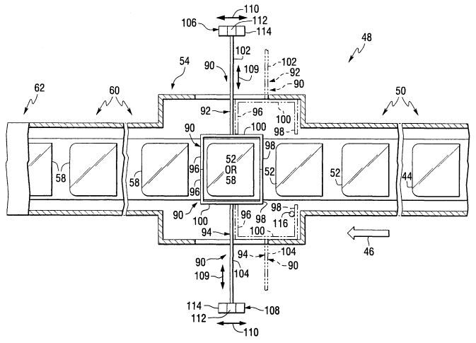
Nonlimiting embodiments of the invention will be discussed
using the lehr 48 shown in Fig. 2. With reference to Fig. 2, there is shown
heat extracting member, 90 incorporating features of the invention. The
:15 member 90 includes a.first section 92 and a second section 94. The
sectibns.~. _
92 and 94 are similar in,construction and each includes a pair of elongated
heat extracting arm members 96 and 98 connected by elongated heat
extracting intermediate arm member 100. Although not limiting to the
invention, the free ends of the arm members 96 and 98 are closed. The heat
extracting arm members 96, 98 and 100 are discussed in detail below. An
elongated rod 102 has one end connected to the intermediate heat-extracting
arm member 100 of the section 92, and an elongated rod 104 has one end
connected to the intermediate arm member 100 of the section 94, of the heat-
extracting member 90. The other end of each of the rods 102 and 104 is
connected to a moveable push-pull arrangement 106 and 108, respectively.
The components of the moveable push-pull arrangements 106 and 108 are
not limiting to the invention and each function (a) to move the sections 92
and
94 along a reciprocating path 109 toward one another to position the arm
members 96, 98 and 100 as shown in solid lines in Fig. 2 about a shape
sheet-laden iron 52 (see also Fig. 3) and to move the sections 92 and 94
away from one another, and (b) to move the sections 92 and 94 along a
CA 02603872 2007-10-03
WO 2006/110145 PCT/US2005/012426
-17-
reciprocating path 110 to move the heat extracting member 90 in coordinated
movement with the shaped sheet-laden iron 52 as it moves through the edge
cooling section 54 of the lehr 48, and to position the sections 92and 94 of
the
heat extracting member 90 in a sheet receiving position as shown in phantom
in Fig. 2, after the edge portions of the shaped sheets have been edge
strengthened.
The components of each of the moveable push-pull
arrangements 106 and 108, although not limiting to the invention can include
a push-pull component 112, e.g. but not limiting the invention thereto, a
piston, a rack and pinion arrangement or a chain drive, to move the sections
92 and 94 toward and away from one another, and a moveable platform 114,
e.g. but not limiting to the invention a motor driven plafform or a platform
mounted on electrically powered rails (not shown) of the type used in the art,
th'rough which signals are forwarded to control speed and direction of the
platform, to. move the sections 92: and 94 of the heat extracting member 90
along the reciprocating path 110. ::.
With reference to Figs::2 and 3 as needed, in a nonlimiting
embodiment of the invention, as the shaped sheet-laden iron 52 moves into
the edge cooling section 54, the first section 92 and the second section 94 of
the heat extracting member 90 are in the sheet receiving position as.shown in
phantom at the entrance end of the edge cooling section 54 of the lehr 48.
When a shaped sheet-laden iron 52 moving into the edge cooling section 54
is aligned with the intermediate arm member 100 of the sections 92 and 94, a
sensor 116 activates the push-pull component 112 of the moveable push-pull
arrangements 106 and 108 to move the rods 102 and 104 toward one another
to position the arm members 96, 98 and 100 of the sections 92 and 94 around
the perimeter of shaped glass sheets on the bending iron 10. In Fig. 3, only
the intermediate arm member 100 of the sections 92 and 94 of the heat-
extracting member 90 is shown positioned adjacent the peripheral edge
portions 56 of the glass sheets 38 and 40. As the heat extracting member 90
is positioned around the perimeter of the shaped sheet, the sensor 116 or
CA 02603872 2007-10-03
WO 2006/110145 PCT/US2005/012426
-18-"
timer (not shown) activates the moveable platform 114 of the moveable push-
pull arrangements 106 and 108 to move through heat extracting member 90
along the path 110 toward the exit end of the edge cooling section 54 of the
lehr 48, e.g. to the left as viewed in Fig. 2. As the shaped sheet-laden iron
52
moves through the edge cooling section 54, the heat extracting member 90
extracts heat from the peripheral and marginal edges of the glass sheets in a
manner discussed below to strengthen the peripheral edges of the shaped
sheets. After edge portions of the glass sheets are heat strengthened,
portions of the rods 92 and 94 are moved out of the edge cooling section 54
by the push-pull component 112 of the moveable push-pull arrangements 106
and 108 to move the sections 92 and 94 away from one another. The edge
strengthened sheet-laden mold 58 continues to move through the edge
cooling section 54 into the annealing section 60 of the lehr 48 as the
sections
92 and 94 are.moved upstream, by the-moveable platforms 114 of the
moveable push-pull arrangements 106 and:108 into their initial position to
await the next shaped sheet-laden mold 52:-
As can be appreciated, the invention is not limited to having one
heat extracting member 90 incorporating features of the invention in the edge
cooling section 54 of the lehr 48. For example, but not limiting to the
invention, two or more heat extracting members can be provided to have one
heat extracting member cooling the edges of the glass sheets, a second heat
extracting member in the initial position, and a third heat extracting member
moving toward the initial position, and/or any other combinations thereof.
With reference to Figs. 4 and 5 as needed, in another
nonlimiting embodiment of the invention, after the open top box 72 having the
shaped sheet-laden iron 52 moves into the zone 79 (see Fig. 4), edge cooling
device 120 incorporating features of the invention shown in Fig. 5 is moved
into the box 72 in any convenient manner to position heat extracting member
122 around the perimeter or edges 56 of the shaped sheets 38 and 40, for the
heat extracting member 90. The edges of the shaped glass sheets are cooled
in a manner to be discussed below to cool the perimeter of the sheets at a
CA 02603872 2007-10-03
WO 2006/110145 PCT/US2005/012426
-19-
faster rate than the center portions of the sheets to strengthen the edge
portions of the sheets. After the edges of the sheets are cooled for a
predetermined time, the edge-cooling device 120 is moved out of the box 72.
The box 72 having the edge strengthened shaped sheet-laden iron 58 is
moved from the compartment 79 to the compartment 80 as the next box 72
having the shaped sheet-laden iron 52 moves from the compartment 78 to the
compartment 79.
As can be appreciated, the edge-cooling device 120 can be
lowered into the box 72 to position the heat extracting member 122 around
the edges of the shaped sheets and lifted out of the box 72 in any convenient
manner, e.g. but not limiting to the invention using the elevator mechanism
discussed in USPN's 4,894,080 and 5,049,178 for raising and lowering the
mechanical and/or air-pressured bending mechanism: discussed in the
patents.
In the following discussion several nonlimiting embodiments of
the invention to extract or remove heat from the :peripheral edge portions of
the sheets are discussed; however, as will be appreciated, the invention is
not
limited thereto. Extracting heat from the peripheral edge portions of the
sheets to cool the peripheral and marginal edge portions of the sheets faster
than the central portions of the sheets can be accomplished by moving a
liquid toward peripheral edge portions of the glass sheets, e.g. moving gas
through the arm members 96, 98 and 100 of the sections 92 and 94 (Fig. 2),
and heat extracting member 122 (Fig. 5); by applying a vacuum, e.g. pulling a
vacuum through the arm members 96, 98 and 100 of the sections 92 and 94
to pull the heated air in the edge cooling section 54 of the lehr 48, and
pulling
vacuum through the heat extracting member 122 to pull the heated air in the
compartment 79 of the furnace 70, over the peripheral and marginal edges of
the shaped sheets to cool and edge strengthen the peripheral and marginal
edge portions of the glass sheets, and/or by positioning a heat absorbing
body, e.g. providing radiant absorbing arm members 96, 98 and 100, and
radiant absorbing heat extracting member 122 adjacent the peripheral edge
CA 02603872 2007-10-03
WO 2006/110145 PCT/US2005/012426
-20-
portions 56 of the sheets 38 and 40 to absorb radiant heat from the peripheral
and marginal edge portions of the glass sheets.
In the following discussion the arm members 96, 98 and 100,
and the heat extracting member 122 are manifolds to move a cooling liquid,
e.g. air, or pull a vacuum there through to cool and strengthen the edges of
the glass sheets. With reference to Fig. 6, a segment 130 for controlling the
flow of air toward the peripheral edges of the sheets, or for pulling a vacuum
adjacent the peripheral edges of the sheets is shown. The segment 130 is
not limiting to the invention and can be a segment of the heat extracting arm
members 96, 98 and 100 of the heat extracting member 90 (see Fig. 2) and/or
a segment of the heat extracting member 122 (see Fig. 5.). Surface 132 of
the member 130 faces the edges 56 of the glass sheets 38 and 40 and has a
plurality of spaced holes 134 and a slidably mounted plate 136. With the plate
136 moved and positioned to the left as shown in Fig. 6, e.g. open position,
the holes or passageway openings 134. are exposed, and with the plate 136
moved to the right, e.g. closed position (not shown) the holes or passageway
openings 134 are covered. The plate 136 can be in the closed position as the
sections 92 and 94 (Fig. 2) move from the initial position to the engaging
position, and as the heat extracting member 120 moves into the box 72 (Fig.
5), to prevent premature cooling of the edges of the glass sheets. When
members 92 and 94 or member 120 is in its cooling position, plate 136 to its
open position so that edges 56 can be cooled. After the edges of the sheets
are cooled and strengthened, the plate 136 can be moved back over the holes
134 to prevent cooling of the environment as the sections 92 and 94 are
moved toward initial positions in the edge cooling section 54 of the lehr 48,
or
the heating extracting member 120 is lifted out of the box 72. As can be
appreciated, the plate 136 can be eliminated. In this instance, the gas or
vacuum is turned off as the sections 92 and 94, or the heat extracting member
120 moves into position, and the gas or vacuum is turned on when the
sections, or heat extracting member are in position.
CA 02603872 2007-10-03
WO 2006/110145 PCT/US2005/012426
-21 -
Although not limiting to the invention, but to provide an
appreciation of the interaction of certain parameters the following discussion
is presented. The amount and rate of heat extracted from the edges of the
sheets for purposes of this discussion are a function of the difference
between
the temperature of the heat extracting medium, e.g. a liquid such as but not
limited to gas, a vacuum or a radiant absorbing body, and the edges of the
glass sheets; the temperature difference between the edges of the glass
sheet and the interior of the glass sheet, and the thickness of the glass
sheet.
In the following discussion, although not limiting to the invention, the glass
sheets have a thickness of 1.6 to 5 millimeters. As the temperature of the
heat extracting medium decreases and the temperature difference between
the heat extracting medium and the edges of the glass sheets increase while
the temperature difference between the edges of the glass sheets and the
interior of the glass sheets, and the temperature of the interior of the edge
1.5. '. cooling section remain constant, the amount and rate of heat
extracte6.from
the edges of the glass sheets increases and vice versa. As the temperature
of the glass edges decreases and the temperature difference between the
edges of the glass sheet and the interior of the glass sheets increases while
the temperature difference between the heat extracting medium and the
edges of the glass sheets remain constant, the amount and rate of heat
extracted from the edges decreases and vice versa. As the amount and rate
of heat extracted from the edges of the glass sheets increases, the edge
strength increases and vice versa. The temperature of the interior of the edge
cooling section 54 of the lehr 48 and the temperature of the compartment of
the furnace 70 where the invention is practiced to edge strengthened the
shaped glass sheets has an effect on the rate of cooling. In the above
discussion the temperature of the edge cooling section 54 and the
compartment of the furnace 70 where the invention is practiced is taken into
account by considering the heat of the glass sheets.
As can be appreciated, the temperature difference between the
edges of the glass sheets and the interior of the glass sheets should not.
CA 02603872 2007-10-03
WO 2006/110145 PCT/US2005/012426
-22-
exceed the temperature at which the stress in the edges of the glass sheets
result in fracturing the edges of the glass sheets. For soda-lime-silicate
glass
the temperature differential should not exceed 250 F (121 C), for example
not more than 200 F (33 C).
The amount and rate of heat extracted by the medium, e.g. gas,
vacuum or radiant heat absorbing body, for purposes of this discussion
depends on the following parameters. For gas, the parameters to be
considered are the temperature of the gas, the area of gas flow openings, e.g.
holes 134 shown in Fig. 6, and the distance between the openings, e.g. the
surface 132, and the edges 56 of the sheets 38 and 40 (see Fig. 3), the gas
flow, the gas pressure and heat absorbing property of the gas. As the
temperature of the gas increases while the remaining parameters remain
constant, the rate and amount of heat extracted decreases and vice versa; as
the area of gas flow openings increase while the remaining parameters
remain constant, the amount of heat extracted can'be expected to decrease:
and. vice versa; as the distance between the openings and sheet edges
increase while the remaining parameters remain constant, the amount and
rate of heat extracted can be expected to decrease and vice versa; as the gas
flow increases while the remaining parameters remain constant, the amount
and rate of heat removal increases and vice versa; and as the heat
absorbance of the gas increases, while the remaining parameters are kept
constant, the rate of heat removal and depth of temper increases and vice
versa.
The invention is not limited to the system used to move a liquid,
e.g. gas into the arm members 96, 98 and 100 of the sections 92 and 94 of
the heat-extracting member 90 shown in Fig. 2 or the heat extracting member
122 of the heat extracting device 120 shown in Fig. 5. For example, but not
limiting to the invention, the gas can be moved through the rods 102 and 104,
through the intermediate arm members 100 and thereafter through the arm
members 96 and 98 of the sections 92 and 94 shown in Fig. 2, and through
openings 140 in hollow support rods 142 to the heat extraction member 122
CA 02603872 2007-10-03
WO 2006/110145 PCT/US2005/012426
-23-
shown in Fig. 5. To prevent chilling of the edge portions of the glass sheets
too quickly, the gas is preferably at a temperature in the temperature range
of
700 to 800 F.
In one nonlimiting embodiment of the invention, gas is used to
extract heat from the edge portions of the glass sheets. As can be
appreciated, the invention is not limited to the type of gas used; however
because the gas is used in a heated environment, gas or gas mixtures that
would combustion in such an environment are not recommended and should
not be used. Gases that can be used in the practice of the invention, but not
limited thereto include air, carbon dioxide, nitrogen, argon and other inert
gas
and mixtures.
In the practice of the invention, it is preferred to extract sufficient
heat to provide edge compression of at least 3000 psi, e.g. 3,000 - 5,000 psi
(20.7 - 34.5 x 10⁶ Pa). The. invention contemplates the edge strengthening or
tempering the peripheral edge of the glass sheet. As can be appreciated, the
invention.is not limited thereto and can extend from the peripheral edge of
the
sheet, e.g. but not limiting to the invention in the marginal edge portions of
the
sheet within a distance of about 0.125 inch (0.32 centimeter) from the surface
of the peripheral edge of the glass sheets. In the practice of the invention,
a
gas manifold was placed around a pair of shaped glass sheets each having a
thickness of 2.1 millimeters supported on a bending iron. The manifold was
spaced 0.5 inches from the edge. The manifold had holes 134 having an
open area of 0.0122 square inches and on a spacing of 0.25 inches. Air
heated to a temperature of 600 F(316 C) was moved through the holes at a
rate of 12 standard cubic feet per minute per foot of treated edge. The edges
of the glass sheets were cooled for a period of 30 seconds and had edge
strength of 4000 psi.
Consider now the use of vacuum to extract heat from the edges
of the glass sheets. The parameters to consider when vacuum is used are
the amount of vacuum pulled, the area of the openings, e.g. the holes 134
shown in Fig. 6, the distance between the openings, e.g. the surface 132, and
CA 02603872 2007-10-03
WO 2006/110145 PCT/US2005/012426
-24-
the edges 56 of the sheets 38 and 40 (see Fig. 3), the distance between the
adjacent vacuum holes, and the temperature of the edge cooling section 54 of
the lehr 48 (see Fig. 2) or compartment of the furnace 70 where the edges of
the glass sheet are cooled (see Fig. 4). As the amount of vacuum pulled
increases while the remaining parameters remain constant, the amount of
heat absorbed increases and vice versa; as the area of the openings increase
and the remaining parameters remain constant, the amount of heat extracted
increases and vice versa; as the distance between the openings increases
while the remaining parameters remain constant, the amount of heat
extracted decreases and vice versa, and as the distance between the
openings through which the vacuum is pulled and the edges of the glass
sheets increases while the remaining parameters remain constant, the
amount of heat extracted decreases and vice versa. As the temperature of
the edge cooling section 54 of the furnace 48 and of the compartment of the
furnace 70 where the edges of the glass sheet are cooled increases whiie the
::
remaining parameters remain constant, the amount of heat extracted from the
sheet decreases and vice versa.
The invention is not limited to the system used to pull the
vacuum through the arm members 96, 98 and 100 of the sections 92 and 94
of the heat-extracting member 90 shown in Fig. 2 or the heat-extracting
member 122 of the heat-extracting device 120 shown in Fig. 5. For example,
but not limiting to the invention, a vacuum can be pulled through the rods 102
and 104, through the intermediate arm members 100, and thereafter, through
the arm members 96 and 98 of the sections 92 and 94 shown in Fig. 2, and
through openings 140 in hollow support rods 142 of the heat extraction
member 122 shown in Fig. 5.
A still further nonlimiting technique of the invention to extract
heat from the edges to strengthen the edges of the glass sheets is to use a
radiant heat-absorbing member (hereinafter "RHA member"). The parameters
to be considered are the heat absorbing coefficient of the RHA member, the
emissivity of the RHA member, the distance between the RHA member and
CA 02603872 2007-10-03
WO 2006/110145 PCT/US2005/012426
-25-
the edges of the glass sheets, the heat in the edge cooing section 54 of the
lehr 48 (see Fig. 2) or the compartment of the furnace 70 where the edges of
the glass sheets are cooled (see Fig. 4), and the rate of heat extraction from
the RHA member, e.g. water cooling pipes contacting the surfaces of the RHA
member other than the surface absorbing heat from the edges of the glass
sheets. As the heat absorbing coefficient of the RHA member increases while
all the other parameters are kept constant, the heat absorbed from the edges
of the glass increases and vice versa; as the emissivity of the RHA member
increases while the remaining parameters remain constant the heat absorbed
from the glass edges increases and vice versa; as the distance between the
RHA member and the edges of the glass sheet increases while the remaining
parameters remain constant, the amount of heat adsorbed decreases and
vice versa; as the heat in the surrounding area, e.g. the edge cooling section
54 of the Iehr 50 or the compartment of the furnace 70 where the edges of the
glass sheets are cooled increases~.while the remaining parameters are kept
constant, the rate of heat absorbed from the edges of the sheet decreases
and vice versa, and as the heat extracted from the RHA member by the
cooling medium increases while the remaining parameters remain constant,
the heat removed from the edges of the sheets increases, and vice versa.
The invention is not limited to system used to extract heat using
a RHA member. For example, but not limiting to the invention, pipes through
which cooling water is circulated, e.g. the arm members 96, 98 and 100, and
the heat extracting member 122 would function as cooling pipes and would
not have the passageways 134 shown in Fig. 6. Discreet RHA members or a
continuous strip of a RHA member, e.g. a black body such as a carbon body,
are (is) mounted on the surface of the arm members, and surface of the heat
extracting member facing the edges of the glass sheets. A cooling medium,
e.g. water, moves through one chamber of a dual chamber in the rods 102
and 104, the intermediate arm members 100 and thereafter through the arm
members 96 and 98 of the sections 92 and 94 shown in Fig. 2, and the return
water moves through the other chamber of the dual chamber through the arm
CA 02603872 2007-10-03
WO 2006/110145 PCT/US2005/012426
-26-
members 96 and 96, the intermediate arm member 100 and the rods 102 and
104. For the heat-extracting member 122 shown in Fig. 5, the cooling
medium is moved through opening 142 in one of the support rods 140 through
the heat-extracting member 122 and out of the opening 140 of the other
support rod 140.
As can be appreciated, the invention is not limited to the manner
in which the heat extracting members are positioned around the edges often
sheets, e.g. but not limiting the invention thereto, the arm members 96, 98,
100 (see Fig. 2) can be separately mounted and separately move toward or
away from their respective edges to cool the edge portions of the sheets as
discussed, or the arm members 96, 98 and 100 can be connected to a
common support e.g. support ring (not shown) which may be raised or
lowered to move the arm members 96, 98 and 100 toward and away from the
edges of the sheets, or the sheets lowered. Or raised, to position the edges
of
the sheets in facing relationship to the arm::members 96, 98 and 100 or the
heat extracting member 122. . .. . . .
As can be appreciated, the invention is not limited to the manner
in which the gas, vacuum or water is supplied. For example, but not limiting
to the invention, the gas, vacuum or water can be supplied by plant piping or
storage units (now shown).
Nonlimiting embodiments of the invention contemplate
strengthening the full periphery of the sheets (see Figs. 2 and 5) or selected
zones of the periphery of the glass sheets (see Fig. 7) (hereinafter also
referred to as "zone heating" or "zone edge strengthening"). As shown in
Fig. 2, the arm members 96, 98 and 100 of the first and second sections 92,
94 of the heat extracting member 90, and as shown in Fig. 5 the heat
extracting member 122 surrounds the full periphery or edge portions 56, to
extract heat from the full periphery or edge portions, to edge strengthen the
full periphery or edge portions 56, of the sheets 38 and 40.
With reference to Fig. 7, there is shown a nonlimiting
embodiment of the invention to strengthen edge zones of the periphery. More
CA 02603872 2007-10-03
WO 2006/110145 PCT/US2005/012426
-27-
particularly, as shown in Fig. 7, heat extracting member 150 includes heat
extracting members 152 - 155 mounted on a frame 167 by hollow support
rods 169 - 172, respectively to position the heat absorbing members
152 - 155 in facing relationship to selected peripheral edge portions, e.g.
but
not limiting to the invention, the center portion of the long sides of the
sheets
and the sides of the sheets as shown in Fig, 7. The selected edge portions
are cooled using the RHA member, and/or moving a cooling medium through,
or pulling a vacuum through members 152-155 as discussed earlier, e.g.
through holes 174 in the support rods 169-172.
Zone edge strengthening can be used when a process or design
applies more stress to selected edge portions of the glass sheet(s) than to
other edge portions. The invention contemplates zone cooling any portion of
the edges of the sheets, e.g. but not limiting to the,invention, cooling two
edges, e.g. opposite edges of the glass sheets; cooling only the middle
portions of the edges of the glass sheets. As can be ;appreciated, in those
instances where fractures are observed only in.a given-.portion of the edge,
e.g. as a result of design or equipment handling the glass sheets, the edges
can be strengthen by cooling only that edge portion.
A nonlimiting technique to zone cool the edges of the glass
sheets is to absorb heat along a gradient similar to the gradient of edge
strength desired. For example but not limiting to the invention, positioning
the
heat absorbing member around the full periphery of the sheet and move gas
or pull vacuum through holes having various size openings, or having holes of
uniform size and cooling the edges as the heat extracting sections 92 and 94
(Fig. 2) are moved from the initial position to the work position; the gas or
vacuum is discontinued when the sections 92 and 94 encircle the periphery of
the sheets. The edge portions first cooled are cooled for a longer period of
time than the edge portions last cooled and will have greater edge strength.
Another technique for zone cooling is to have holes, e.g. the holes 134 of
Fig. 6 with different sized opening. The larger the opening the more air flow
moving out or vacuum pulled and the more cooling of the edge. As can be
CA 02603872 2007-10-03
WO 2006/110145 PCT/US2005/012426
-28-
appreciated other techniques can be used to cool the glass at different rates
or at different positions for zone cooling or gradient cooling using gas,
vacuum
or a RHA member.
As can be appreciated, the particular embodiments described in
detail herein are illustrative only and are not limiting to the scope of the
invention, which is to be given the full breadth of the appended claims and
any and all equivalents thereof.