Note: Descriptions are shown in the official language in which they were submitted.
CA 02603884 2011-01-19
WO 2006/106552 PCT/1T2006/000216
1
Support Frame and Cover Plate for
Wall Mounting an Electrical Apparatus
DESCRIPTION
The present invention relates to the technical field
of electrical systems for homes and offices, and more in
particular, it relates to a support frame and a composite
structure, or group of parts, including such frame, for
wall-mounting one or more electrical apparatuses.
For the purposes of the present description, by
electrical apparatus we mean, in general, any means or
electrical device generally being part of electrical
installations in civil buildings and the like and usually
intended to be mounted, for example built in, onto walls
of such buildings.
This definition therefore includes, not limitingly,
switches, electrical power sockets, sockets for data
networks, TV sockets, telephone sockets, buttons,
commutators, deviators, electrical adjustment devices in
general, connectors, thermostats, timers, fuse holders,
alarms/buzzers, emergency lights, for example removable,
signalling lights, for example step markers, displays,
for example LCD and the like.
As known, many of the aforementioned electrical
apparatuses are usually installed on a wall using
composite mounting structures, or groups of parts,
CA 02603884 2007-10-04
WO 2006/106552 PCT/IT2006/000216
generally including:
- a box intended to be built into the wall;
- an apparatus-carrying mounting frame (or support frame)
fixable to the box and comprising a frame body developing
about an opening defining a mounting seat suitable for
receiving and holding one or more electrical apparatuses;
and
- a cover plate that can be removably fixed to the frame
and provided with an opening for allowing a user to gain
access, visually or manually, the electrical apparatuses
installed on the support frame.
In the prior art, several systems are known for
removably fixing a cover plate to a support frame. For
example, screw fixing systems are known, which despite
being sturdy are almost outdated since they are
unaesthetic.
Several snap-wise fixing systems between plate and
frame also belong to the prior art. For example, it is
known to provide a plurality of tongues on an edge
portion of the plate intended for facing the support
frame, adapted for engaging snap-wise with respective
protruding edges provided on the external perimeter of
the support frame.
The snap-wise fixing systems of the prior art,
despite being highly used, in some cases exhibit a
CA 02603884 2007-10-04
WO 2006/106552 PCT/IT2006/000216
3
problem of fragility of the snap-wise fixing elements, in
other cases are not such as to prevent an accidental
detachment of the plate from the support frame.
The object of the present invention is to provide a
support frame which should be provided with an innovative
fixing system to a cover plate and which should allow
overcoming the disadvantages described above with
reference to the prior art.
Such object is achieved by a support frame as
defined in the annexed first claim in the most general
form thereof and in the dependent claims in some
particular embodiments.
The object of the present invention also is a group
of parts as defined in the annexed claim 10.
The invention shall be better understood from the
following detailed description of a particularly
preferred embodiment thereof, made by way of a non-
limiting example with reference to the annexed drawings,
wherein:
- figure 1 shows a side view of a particularly
preferred embodiment of a plate-frame group according to
the present invention;
- figure 2 shows a front plane view of the support
frame belonging to the plate-frame group shown in figure
1;
CA 02603884 2007-10-04
WO 2006/106552 PCT/IT2006/000216
4
- figure 3 shows an axonometric section view of the
support frame of figure 2;
- figure 4 shows an axonometric view of a sheet
element associable to the support frame of figure 2;
- figures 5a and 5b show a partial section view of
the plate-frame group of figure 1 in two different
operating positions between the covering plate and the
support frame; and
- figure 6 shows an enlarged detail of the cover
plate of the plate-frame group of figure 1.
In the figures, like or similar elements shall be
indicated by the same reference numerals.
Figure 1 shows a side view of a particularly
preferred embodiment of a plate-frame group of parts,
globally indicated with reference numeral 1, according to
the present invention.
The plate-frame group of parts includes a support
frame 2 and a cover plate 3 removably fixable to the
support frame 2. For fixing to the support frame 2,
fixing elements shaped as tongues 4 are provided on face
5 of the cover plate 2 facing the support frame 3.
Preferably, the cover plate 3 includes four fixing
tongues 4, of which only two are visible in figure 1.
As is known to the man skilled in the art, the role
of such a cover plate 3 is both that of ensuring a
CA 02603884 2007-10-04
WO 2006/106552 PCT/IT2006/000216
minimal protection for the electrical apparatuses, for
example from dust, and of that preventing dangerous
access (for example, through pointed objects) to the
electrically conducting parts of the electrical
5 apparatuses. Another fundamental task assigned to the
cover plates, moreover, is that of hiding any
imperfections produced for example by the presence of the
mounting frame and box which, rather than having an
aesthetic value, have a functional value that is
difficult to combine with aesthetic requirements or
standards.
The cover plate 3 is substantially shaped as a frame
and is provided with a central opening, not visible in
figure 1, for allowing a user to access, visually or
manually, the electrical apparatuses installed on the
support frame 2.
The support frame 2 is in turn fixable to the wall,
for example by a pair of screws 6 adapted for holding the
support frame 2 anchored to a box flush mounted in the
wall, not shown in the figures.
As is better seen in the plan view shown in figure 2,
the support frame 2 includes a frame body 7, preferably
made of an insulating material and approximately having
the shape of a substantially plate-shaped frame, as a
non-limiting example, with quadrangular plan with rounded
CA 02603884 2007-10-04
WO 2006/106552 PCT/IT2006/000216
6
corners. By way of an example only, the frame body of
frame 7 is shown with a substantially rectangular shape.
In the example, a pair of through holes 8,
preferably slotted, is provided in the frame body 7 of
frame 2. The through holes 8 are such as to be crossed by
respective screws 6 in order to fix the support frame 2
to the box flush mounted in the wall.
The frame body 7 of the support frame 2 develops
about a mounting. window 9, defining a mounting seat
adapted for receiving or holding one or more electrical
apparatuses, not shown in the figures. Two opposed walls
10 of the support frame 2 face the mounting window 9,
each including a plurality of hooking elements 11 that
project from walls 10 towards the mounting window 9.
These hooking elements 11 are such as to cooperate with
corresponding hooking elements provided on two opposite
sides of the electrical apparatuses to be hooked to the
support frame 2. Preferably, such hooking elements 11
allow obtaining a joint-wise and a snap-wise hooking of
the electrical apparatuses to the support frame 2.
The support frame 2 further includes fixing means 12
for removably fixing the cover plate 3 to the support
frame.
Advantageously, such fixing means 12 comprises
fixing channels 12 adapted for receiving respective
CA 02603884 2007-10-04
WO 2006/106552 PCT/IT2006/000216
7
fixing tongues 4 of the cover plate 3. Preferably but
non-limiting, the number of fixing channels 12 provided
in the support frame 2 is equal to four.
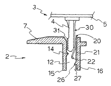
A fixing channel 12 is better visible in figure 3,
which shows a section view along axes x-x and y-y of the
support frame 2 of figure 2. In particular, a sectioned
fixing channel 12 is visible in such figure.
The fixing channel 12 exhibits an end 13 jointed to
an opening 13 obtained in the frame body 7 of the support
frame 2, so as to receive therein, through opening 13, a
fixing tongue 4 of the cover plate 3. Preferably, as
shown in figure 3, the edge of the frame body 7
delimiting such opening 13 is chamfered so as to favour
the introduction of the fixing tongue 4 into the fixing
channel 12.
Advantageously, the fixing channel 12 includes
relief means 14 therein. Preferably, such relief means
includes at least one protruding edge 14, for example
with triangular profile, projecting from a wall 15 of the
channel inwards of channel 12.
Advantageously, the fixing channel 12 further
includes pushing means 20 opposite the relief means 14.
In figure 3, for clarity, the pushing means 20 is shown
separate from the fixing channel 12. Such pushing means
20, 21 is such as to exert a pressure against the fixing
CA 02603884 2007-10-04
WO 2006/106552 PCT/IT2006/000216
s
tongue 4 of the cover plate 3, so that a surface of such
fixing tongue 4 engages pressure-wise against the
protruding edge 14 when the cover plate 3 is fixed to the
support frame 2.
In a particularly advantageous embodiment, the
pushing means 20, 21 includes a tooth 21 flexible and
inclined relative to the direction of extension of the
fixing channel 12. Such tooth has an end 22 protruding
inwards of channel 12 and an opposite end 23 constrained
to the wall of channel 16 opposite the wall of channel 15
including the relief means 14. Preferably, end 22 of
tooth 21 protruding inwards of channel 12 is a curved end.
In a particularly preferred embodiment, the flexible
tooth 21 is a metal tooth being part of a sheet element
20 insertable, preferably joint-wise and snap-wise, in a
notch 25 adjacent the fixing channel 12.
The sheet element 20 is shown in a partial view in
figure 3 and in an overall and more detailed view in
figure 4. Such sheet element 20 preferably is a metal
sheet including a frame base portion 20a, 20b, 20c, 20d
intended for being inserted in notch 25. The frame base
portion 20a, 20b, 20c, 20d consists of four walls
substantially parallel by twos. One of such walls, that
is, wall 20a, is jointed to the flexible tooth 22. Wall
20c opposite wall 20a, in the introduction of sheet 20
CA 02603884 2007-10-04
WO 2006/106552 PCT/IT2006/000216
9
into notch 25, is intended for passing over a projecting
element 26 which protrudes from the wall of channel 16,
for locking snap-wise sheet 20 to the support frame 2.
Preferably, wall 20c of sheet 20 exhibits a wall portion
27 slightly inclined relative to the plane on which the
base portion 20a, 20b, 20c, 20d of sheet 20 lays, in
order to allow the projecting element 26 to be passed
over by wall 20c in the snap-wise introduction of sheet
20 into notch 25.
Preferably, the other two walls 20b, 20d of the
sheet element 20 exhibit a notched outside edge
advantageously adapted for allowing the forced and
irreversible mounting of sheet 20 into notch 25.
Figures 5a and 5b show two partial views of the
cover plate 3 and of the support frame 2 in two different
operating positions. In such figures, the cover plate 3
advantageously includes a fixing tongue 4, provided with
a first surface 31 at least partly shaped as a saw tooth
and a second surface 30 substantially smooth and opposite
the first shaped surface 31.
The first surface 31, thanks to the pushing action
exerted by tooth 21 is such as to engage pressure-wise
against the protruding edge 14 provided in the fixing
channel 12 for holding the cover plate 3 constrained to
the support frame 2.
CA 02603884 2007-10-04
WO 2006/106552 PCT/IT2006/000216
The second surface 30, during the introduction of
the f ixing tongue 4 in the f ixing channel 12 is such as
to interfere by sliding against the flexible tooth 21.
After the introduction, the flexible tooth 21 is such as
5 to exert a pushing action on such surface 30 which
determines a slight bending of the fixing tongue 4.
Thanks to such bending, not visible in the figures, the
shaped surface 31 of the fixing tongue 4 is held
pressure-wise against the protruding edge 14 provided
10 inside the fixing channel 12.
In a particularly preferred embodiment, as shown in
figure 6, the fixing tongue 4 has a substantially plate-
like shape and is provided with relief thickening
elements 32, 33 obtained on the surface of tongue 30
intended for cooperating with the flexible tooth 21. In
the practice, the flexible tooth 21 is such as to apply a
pushing force on such elements 32, 33, thus allowing a
constant pressure to be maintained on the fixing tongue 4,
in order to advantageously maintain the disconnection
force of the cover plate 3 from the support frame 2
constant over time, irrespective of the number of
manoeuvres carried out.
In the particularly preferred embodiment of figure 6,
the fixing tongue is further provided with a chamfered
end portion 34 in order to facilitate the centring and
CA 02603884 2007-10-04
WO 2006/106552 PCT/IT2006/000216
11
the introduction of the fixing tongue 4 into the fixing
channel 12 of the support frame 2.
Based on the description above, it is therefore
possible to understand how a support frame 2 according to
the present invention allows making the application of a
cover plate 3 thereto particularly easy.
It should be noted that the provision of pushing
means into the fixing channel allows obtaining a reliable
fixing of the cover plate 3 to the support frame 2
without imposing an excessive stress of the structural
parts that ensure the fixing of the cover plate 3 to the
support frame 2.
Advantageously, the provision on the fixing tongue
4 of a surface 31 shaped as a saw tooth and adapted for
cooperating with a relief element 14 provided in the
fixing channel 12 allows aligning the cover plate 3
parallel to the fixing wall also when, for example due a
non-prefect installation of the flush mounted box into
the wall, the frame body 7 of the support frame 2 is not
perfectly aligned with such fixing wall.
Moreover, it should be noted that, advantageously,
the provision of a pushing tooth against a curved surface
allows such tooth not to jib against the fixing tongue 4
during the removal of the cover plate 3 from the support
frame 4.
CA 02603884 2007-10-04
WO 2006/106552 PCT/IT2006/000216
12
Of course, the man skilled in the art can mane
numerous modifications and variations to the support
frame described above, in order to satisfy contingent and
specific requirements, all of which are in any case
covered by the scope of protection of the invention as
defined by the following claims.