Note: Descriptions are shown in the official language in which they were submitted.
CA 02603951 2007-10-03
LIVE/BAIT WELL VENTILATION VENT
Field of Invention
This invention relates generally to fishing boats having live wells for
the catch or bait and more particularly to a ventilation vent for fresh air
for the
live well of a fishing boat with a live well and incorporating the air vent
unit.
Background of Invention
Fishermen have struggled for year to increase survival rates of their
catch. Whether it be to transport live bait to one's fishing destination,
bringing home the catch, returning the fish to the same or different water
source, or participating in today's popular fishing tournaments, the desire
and
necessity to keep fish alive has always been important. Clearly, in the last
30
years, there has been much advancement in live or bait wells. With onboard
pump/recirculating/aeration systems, the mortality rates of fish have
declined.
However, the effects on fish being subjected to extreme live or bait well
conditions effects of hypothermia, and hyperthermia. Often the conditions in
a live well are much warmer than the temperature of the environment, that a
fish was caught in. This warmer condition causes stresses to the fish from
experiencing the effects of hyperthermia. In this state, fish, which are cold
blooded, expend more energy and use more oxygen from the live well water.
Some fisherman, to get the effects of warmer well conditions, often add ice to
the live well to reduce temperatures, but if too much ice is added fish can
then experience the effects of hypothermia. In addition, fish are then
experiencing a rapidly changing environment, which leads to increase stress
upon the fish.
It is beneficial to keep fish alive in conditions as close as possible to
that of the environment they were caught in to survive best in live well
conditions. This is the function of the boat live well vent unit disclosed
herein.
A search of patents on the subject of venting a live well brought to
light the following United States Patent Nos. 6,038,993; 5,632,220;
-1-
CA 02603951 2007-10-03
5,331,914; 6,729,066131; 6,354,23861; 6,192,820B1; 5,586,406; 5,212,902;
5,191,732; 5,038,515; 4,615,137; 5,231,789; 3,367,061; 2,800,741;
5,249,388; 6,748,695B2; 5,267,410 and 4,845,886.
These references teach methods and devices for improving live wells
and recirculating of fluid therein; however, the references fail to teach or
suggest a ventilation vent device for solving the ventilation/temperature
control problem in a live well on a boat.
Summary of the Invention
Typical fishing boats having a closed live well for holding a selected
volume of water and a live well ventilation vent unit mounted in a top wall
overlying well. The live well vent unit is an open ended elongate sleeve that
projects through the wall into the well. There is a partition dividing the
interior
of the sleeve into first and second separate vertical disposed air flow
passages.
Baffles extend from the upper end of the partition and overlying a portion of
the
respective passages exposed to atmosphere. The baffles slope upwardly and
outwardly away from the partition and terminate in a free outer edge spaced a
selected distance from the adjacently disposed end of the sleeve. The space
between the baffle and sleeve defines a crescent shaped opening for the flow
of air there through. The free outer edge of the baffle is spaced vertically
from
the upper end of the sleeve to catch and deflect a current of air into the
well
above the water therein.
Furthermore, the live well ventilation vent unit for a boat comprises an
open ended sleeve, a partition dividing the interior into first and second
separate
air flow passages through the sleeve, baffle means extending from the
partition
and overlying a portion of the respective passages. The baffle means slopes
upwardly and outwardly away from the partition and terminates in a free outer
edge spaced a selected distance from the adjacently disposed end of the
sleeve.
Moreover the live well ventilation vent unit can incorporate a mounting flange
projecting outwardly beyond the outer perimeter of the sleeve. The sleeve can
be circular and the space between the baffle and interior of the sleeve can
-2-
CA 02603951 2007-10-03
define a crescent shaped air flow through opening in each of the air flow
passages.
More particularly, the instant invention provides a fishing boat having a
live well for holding a selected volume of water, a cover over the well
separating
the same from atmosphere and a live well ventilation vent unit comprising an
open ended elongate sleeve mounted on the wall and projecting there through.
The sleeve is disposed vertically. A partition divides the interior of the
sleeve
into first and second separate vertical air flow passages. A baffle means
extends from the partition and overlying a portion of the respective passages
exposed to atmosphere. The baffle means slopes upwardly and outwardly away
from the partition and terminating in a free outer edge spaced a selected
distance from the adjacently disposed end of the sleeve defining a butterfly
vent.
Applicants vent unit is designed to allow stagnant, heated air to be
released from the live well, while fishing, thereby keeping the well
environment
close to the day's ambient and water temperatures. The air ventilation vent
unit
is designed so that when travelling air is forced there through creating a
forced
circulation of air resulting in a gradual decrease of the live well water
temperature, and thereby increasing the dissolved oxygen levels of the water.
The ventilation vent unit functions to create a more stable live well
environment.
The live well ventilation vent unit of the present invention is intended for
use in fish holding containment, including but not limited to live wells, bait
wells,
aquariums, etc. The vent unit has multiple functions. The open area of the
vent
unit creates air flow passages to allow heat to escape from the fish holding
containment as fresh cooler air is pulled therein. The ventilatiOn vent unit
creates a venturi effect when any level of air/wind, from any direction
travels
over the unit whether it be from natural air current flows or induced for
example
by boat travel. The vent unit captures and forces air/wind down into the
holding
compartment through one air passage and releases the air/wind out through the
other air vent passage. The air vent prohibits splashing water from escaping
from the fish holding containment through redirection of same back into the
live
well. The vent unit expels stagnant air and releases the trapped air thereby
lowering the temperature of the live well compartment and the temperature of
-3-
CA 02603951 2007-10-03
the water in such compartment. It functions to increase dissolved oxygen
levels
in the water held within the holding containment. The vent unit strives to
stabilize the holding containment with the environmental conditions resulting
in
reduced fish stress and thereby increasing fish survival rates. Factors that
enhance or decrease performance of the vent unit include environmental factors
such as time of the day; daytime temperature; night temperature; wind
velocity;
wind direction, time of year; lake water temperature; dissolved oxygen level
of
lake water; water turbidity etc as well as other factors such as the size of
fish
holding containment; volume of water held within the live well; sophistication
of
existing aeration systems; frequency of aeration use, sophistication of water
pumping and exchange systems; number(s) of fish being held; boat hull design;
boat construction material i.e. fiberglass, aluminum; frequency of boat
running;
speeds of boat running; use of live well /bait well support additives; use of
ice
to cool fish holding containment, and time of use etc.
One preferred embodiment of the live well vent unit for a boat comprises
an open ended sleeve, a partition dividing the interior into first and second
separate airflow passages through the sleeve with baffle means extending from
the partition and overlying a portion of said respective passages. The baffle
means slopes upwardly and outwardly away from the partition and terminates
in a free outer edge spaced a selected distance from the adjacently disposed
end of the sleeve. The sleeve can have a mounting flange projecting outwardly
beyond the outer perimeter of the sleeve.
The sleeve is circular and wherein the space between the baffle and
interior of the sleeve defines a crescent shaped airflow through opening in
each
of the air flow passages.
The construction design of the vent creates a natural interface between
atmospheric air and livewell/ baitwell water to accomplish the following:
1) The vent increases dissolved oxygen in livewell/bait well water by
atmospheric diffusion, augmented surface diffusion, and natural cooling
processes;
-4-
CA 02603951 2007-10-03
2) The vent controls livewell/ bait well air and water temperatures by the
processes of evaporation, evaporative cooling, conduction, and convection;
based on Newtons Law of cooling; and
3) The vent controls metabolic and gas waste buildup in livewell/baitwell
by means of air stripping and vacuum degassing to eliminate supersaturation of
waste and gasses.
Thus, It is an object of the present invention to provide a one piece
ventilation vent which can be inexpensively molded for use in fish holding
containment such as live wells, bait wells, aquariums and the like.
It is an object of the present invention to provide means for heat to
escape from the fish holding containment.
It is an object of the present invention to provide a product which creates
a venturi effect when any level of air/wind, from any direction travels over
the
vent.
It is an object of the present invention to provide a ventilation vent which
captures and forces air/wind down into the holding compartment through the
front louver and release the air/wind out through a rear louver contiguous to
the
front louver but oriented in opposite directions and separate from one
another.
It is another object of the present invention to prohibit water from escaping
from the fish holding containment through the vent.
It is an object of the present invention to intake fresh air and exchange
same with stale air.
It is an object of the present invention to release trapped heat.
It is an object of the present invention to lower the temperature of water
held withing the holding containment.
It is an object of the present invention to increase the dissolved oxygen
level in the water held within the holding compartment.
It is an object of the present invention to stabilize the holding containment
to ambient environmental temperatures.
It is an object of the present invention to provide a ventilation vent
composed of a moldable material, contains no moving pieces and requires no
-5-
CA 02603951 2007-10-03
mechanically powered air or water circulation system to operate other than
movement of the air and/or boat.
It is yet another object of the present invention to reduce fish stress and
increase fish survival rates.
Other objects, features, and advantages of the invention will be apparent
with the following detailed description taken in conjunction with the
accompanying drawings showing a preferred embodiment of the invention.
Brief Description of the Drawings
A better understanding of the present invention will be had upon reference
to the following description in conjunction with the accompanying drawings in
which like numerals refer to like parts throughout the several views and
wherein:
Figure 1 is a perspective view of a portion of a boat with a live well
provided with a fresh air ventilation vent unit in accordance with the present
invention;
Figure 2 is a top plan view of a portion of Figure 1 showing the ventilation
vent with the hinged well cover in a closed position;
Figure 3 is an oblique view of the ventilation vent unit;
Figure 4 is a top plan view of the ventilation vent unit;
Figure 5 is an elevational view of the ventilation vent unit;
Figure 6 is a sectional view taken along line 6-6 off Figure 4 showing the
ventilation vent unit of the present invention;
Figure 7 is a chart of the live well without the vent water temperature over
a period of time;
Figure 8 is a chart of the live well without the vent air temperature over a
period of time;
Figure 9 is a chart of the live well with the vent water temperature over
a period of time; and
Figure 10 is a chart of the live well with the vent air temperature over a
period of time.
-6-
CA 02603951 2007-10-03
Detailed Description of Preferred Embodiment
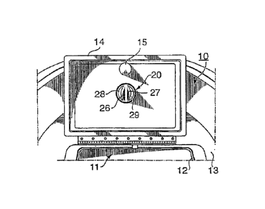
As illustrated in the drawings, a portion of a fishing boat 10 is shown
having a live well 11 accessible though an opening 12 in the boat deck 13. A
lid 14 is hingedly mounted on the deck 13 selectively to cover and uncover
the opening 12. The lid has a finger grip pull unit 15 all of which are
conventional elements known in the art.
In accordance with the present invention the live well is provide with an
air ventilation vent unit 20 which in this instance is mounted on the lid 14.
If
desired it could be mounted anywhere in a portion of the deck 13 closing the
upper part of the live well.
The unit 20 comprises an annular sleeve 21 with a mounting flange 22
extending radially outwardly from one end thereof defining a butterfly shaped
vent unit. The flange has suitably positioned holes for fasteners to securely
mount the unit in the lid 14 with the sleeve projecting through a hole in the
lid
and downwardly into the upper part of the live well when the lid 14 is in its
closed position.
The sleeve 21 internally is divided into air flow through passages 23,
24 by a partition 25. The partition has a pair of baffles 26, 27 secured
thereto
at the upper end thereof. The baffles 26, 27 partially overlie the respective
passages leaving a crescent or quarter moon shaped openings 28, 29 for
flow of air through respective passages 23, 24. The baffles 26, 27 diverge
upwardly away from the partition and have a curved outer edge 30 that at its
highest point is spaced a selected distance above the plane of the upper
surface of the flange 22 this distance being designated A in Figure 6. This
spacing in one preferred embodiment unit was 0.142 inches and provided
satisfactory results.
An experiment was conducted to demonstrate the performance of the
live well with the described vent. Figures 7-10 provide air and water
temperature readings over a set period of time. The live well without the vent
is used as the control. All variables with the exception of the live well
water
and air temperature are considered constant. These variables can include
the time of day, air temperature, wind velocity, wind direction, lake water
-7-
CA 02603951 2014-12-01
'
temperature, oxygen level of lake, water turbidity, gallons of water in
livewell, aeration,
number of fish being held, construction materials of boat, speed of boat,
etc.. Figure 7
and Figure 8 show a rise in the air temperature of the live well without the
vent which
results in a slight increase in the water temperature. The air temperature
then
decreases and the water temperature decreases as well. Figure 9 and Figure 10
show
that the air temperature of the live well with the vent decreases and the
water
temperature virtually stays the same. Other observations made during this test
include:
higher wind velocities decreased the air temperature in the vented live well,
the vent
1.0 live well was able to keep both temperature of the well and water more
consistent to
environmental conditions, and running the boat at extended periods cooled air
temperature to ambient temperature and slowly decreased the water temperature.
The foregoing detailed description is given primarily for clearness of
understanding and no unnecessary limitations are to be understood therefrom,
for
modifications will become obvious to those skilled in the art based upon more
recent
disclosures and may be made without departing from the scope of the appended
claims.
- 8 -