Note: Descriptions are shown in the official language in which they were submitted.
CA 02604088 2007-09-24
Lever-Arch Type File Mechanism
This invention relates to a device for retaining a stack of hole-punched paper
in
a file and, in particular such a device comprising a lever-arch type file
mechanism.
In a conventional lever-arch type file mechanism, a one-armed lever is
provided
for pivoting a pair of arch elements relative to a pair of fixed posts to
allow pieces of
hole-punched paper to be retrieved from or inserted into the file mechanism,
and for
closing the posts and arch elements to form a pair of closed rings to retain
the paper
therein. The pair of arch elements are integrally formed with an intervening
shaped
portion on which a roller attached to the lever travels during pivotal
movement of the
lever, to effect opening or closing of the ring pairs.
In such a conventional file mechanism, when the ring pairs are open, the upper
free end of the lever is very close to, and sometimes even contacts, one of
the arch
elements. Thus, when the ring pairs are open, paper can only be retrieved from
or
inserted into the pair of fixed posts, but no paper can be retrieved from or
inserted
into the pair of pivotable arch elements.
It is thus an object of the present invention to provide a lever-arch type
file
mechanism and a lever-arch type file with such a mechanism in which the
aforesaid
shortcomings are mitigated, or at least to provide a useful alternative to the
public.
According to a first aspect of the present invention, there is provided a
lever-arch type file mechanism including a base; at least two rings extending
upwardly from the base, each said ring including a post member fixed to said
base
and an arch member movable relative to said base and said post member; a lever
assembly movable relative to said base between two stable positions to pivot
said
arch members relative to said post members to selectively move said rings
between
a ring-closed configuration and a ring-open configuration; characterized in
that said
lever assembly includes at least a first arm member and a second arm member,
and
that when said lever assembly is in a first of said stable positions, said
first arm
member is movable relative to said second arm member between an upper position
and a lower posi#ion.
-1-
CA 02604088 2007-09-24
According to a second aspect of the present invention, there is provided a
lever-arch type file including a lever-arch type file mechanism fixedly
secured to a
substrate, said lever-arch type file mechanism including a base; at least two
rings
extending upwardly from the base, each said ring including a post member fixed
to
said base and an arch member movable relative to said base and said post
member;
a lever assembly movable relative to said base between two stable positions to
pivot
said arch members relative to said post members to selectively move said rings
between a ring-closed configuration and a ring-open configuration;
characterized in
that said lever assembly includes at least a first arm member and a second arm
member, and that when said lever assembly is in a first of said stable
positions, said
first arm member is movable relative to said second arm member between an
upper
position and a lower position.
Embodiments of lever-arch type file mechanisms according to the present
invention will now be described, by way of examples only, with reference to
the
accompanying drawings, in which:
Fig. 1 is an exploded view of a lever-arch type file mechanism according to a
first
embodiment of the present invention;
Fig. 2A is a front view of the file mechanism shown in Fig. 1 in a ring-closed
configuration;
Fig. 2B is a side view of the file mechanism shown in Fig. 2A;
Fig. 3 is a front top perspective view of the file mechanism shown in Fig. 2A;
Fig. 4 is a rear top perspective view of the file mechanism shown in Fig. 3;
Fig. 5 is a bottom perspective view of the file mechanism shown in Fig. 3;
Fig. 6 is a sectioned top perspective view of the file mechanism shown in Fig.
3;
Fig. 7A is a front view of the file mechanism shown in Fig. 1 in a ring-open
configuration;
Fig. 7B is a side view of the file mechanism shown in Fig. 7A;
Fig. 8 is a front top perspective view of the file mechanism shown in Fig. 7A:
Fig. 9 is a rear top perspective view of the file mechanism shown in Fig. 8;
Fig. 10 is a sectioned top perspective view of the file mechanism shown in
Fig. 8;
Fig. 11 is an exploded view of the lever assembly of the file mechanism shown
in Fig.
1; -
Fig. 12 is a perspective assembled view of the lever assembly shown in Fig.
11;
-2-
CA 02604088 2007-09-24
Fig. 13A is a front view of the lever assembly shown in Fig. 12 in a fully
extended
configuration;
Fig. 13B is a front view of the lever assembly shown in Fig. 12 in a stable
configuration;
Fig. 14 is an exploded view of a lever-arch type file mechanism according to a
second embodiment of the present invention;
Fig. 15A is a front view of the file mechanism shown in Fig. 14 in a ring-
closed
configuration, with the outer arm of the lever assembly in an upper extended
position;
Fig. 15B is a top view of the file mechanism shown in Fig. 15A;
Fig. 15C is a right side view of the file mechanism shown in Fig. 15A;
Fig. 15D is a left side view of the file mechanism shown in Fig. 15A;
Fig. 16A is a front view of the file mechanism shown in Fig. 15A with the
outer arm of
the lever assembly in a stable lower position;
Fig. 16B is a top view of the file mechanism shown in Fig. 16A;
Fig. 16C is a right side view of the file mechanism shown in Fig. 16A:
Fig. 16D is a left side view of the file mechanism shown in Fig. 16A:
Fig. 17A is a front view of the file mechanism shown in Fig. 14 in a ring-open
configuration;
Fig. 17B is a top view of the file mechanism shown in Fig. 17A;
Fig. 17C is a right side view of the file mechanism shown in Fig. 17A;
Fig. 17D is a left side view of the file mechanism shown in Fig. 17A;
Fig. 18 is an exploded view of a lever-arch type file mechanism according to a
third
embodiment of the present invention;
Fig. 19 is a front view of the file mechanism shown in Fig. 18 in a ring-
closed
configuration in which the outer arm of the lever assembly is in an upper
extended
position;
Fig. 20 is a side view of the file mechanism shown in Fig. 19;
Fig. 21 is a front view of the file mechanism shown in Fig. 19 in which the
outer arm
of the lever assembly is in a lower retracted stable position;
Fig. 22 is a side view of the file mechanism shown in Fig. 21;
Fig. 23A is a front view of the file mechanism shown in Fig. 19 in a ring-open
configuration;
Fig. 23B is a side view of the file mechanism shown in Fig. 23A;
-3-
CA 02604088 2007-09-24
Fig. 24A is a front view of the file mechanism shown in Fig. 23A in which the
outer
arm of the lever assembly is in a retracted stable position;
Fig. 24B is a side view of the file mechanism shown in Fig. 24A;
Fig. 25 is an exploded view of the lever assembly of the file mechanism shown
in Fig.
18;
Fig. 26A is a front view of the lever assembly shown in Fig. 25, as assembled,
with
the outer arm in an upper extended position;
Fig. 26B is a perspective view of the lever assembly shown in Fig. 26A;
Fig. 27A is a front view of the lever assembly shown in Fig. 26, with the
outer arm in
a retracted stable lower position;
Fig. 27B is a perspective view of the lever assembly shown in Fig. 27A:
Fig. 28 is an exploded view of a lever-arch type file mechanism according to a
fourth
embodiment of the present invention;
Fig. 29A is a front view of the file mechanism shown in Fig. 28, in a ring-
closed
configuration, with the outer arm of the lever assembly in an upper extended
position;
Fig. 29B is a side view of the file mechanism shown in Fig. 29A;
Fig. 30A is a front view of the file mechanism shown in Fig. 29A, with the
outer arm
of the lever assembly in a lower retracted stable position;
Fig. 30B is a side view of the file mechanism shown in Fig. 30A;
Fig. 31A is a front view of the file mechanism shown in Fig. 29A in a ring-
open
configuration, with the outer arm of the lever assembly in an upper position;
Fig. 31 B is a side view of the file mechanism shown in Fig. 31A;
Fig. 32A is a front view of the file mechanism shown in Fig. 31A, with the
outer arm
of the lever assembly in a lower retracted stable position;
Fig. 32B is a side view of the file mechanism shown in Fig. 32A;
Fig. 33 is an exploded view of the lever assembly of the file mechanism shown
in Fig.
29A;
Fig. 34A is a front view of the lever assembly shown in Fig. 33, with the
outer arm in
an upper extended position;
Fig. 34B is a perspective view of the lever assembly shown in Fig. 34A;
Fig. 35A is a front view of the lever assembly shown in Fig. 34A, with the
outer arm
in a lower retracted stable position;
Fig. 35B is a perspective view of the lever assembly shown in Fig. 35A;
-4-
CA 02604088 2007-09-24
Fig. 36 is an exploded view of a lever-arch type file mechanism according to a
fifth
embodiment of the present invention;
Fig. 37 is a perspective view of the file mechanism shown in Fig. 36, in a
ring-closed
configuration;
Fig. 38A is a front view of the file mechanism shown in Fig. 37;
Fig. 38B is a side view of the file mechanism shown in Fig. 38A;
Fig. 39 is a perspective view of the file mechanism shown in Fig. 36, in a
ring-open
configuration;
Fig. 40A is a front view of the file mechanism shown in Fig. 39;
Fig. 40B is a side view of the file mechanism shown in Fig. 40A;
Fig. 41 is a perspective view of the lever assembly of the file mechanism
shown in
Fig. 37;
Fig. 42 is a front view of the lever assembly shown in Fig. 41;
Fig. 43 is an exploded view of the lever assembly shown in Fig. 41;
Fig. 44A is a bottom view of the outer arm of the lever assembly shown in Fig.
41;
Fig. 44B is a front view of the outer arm shown in Fig. 44A;
Fig. 44C is an end view of the outer arm shown in Fig. 44A;
Fig. 44D is a perspective view of the outer arm shown in Fig. 44A;
Fig. 45 is an exploded view of a lever-arch type file mechanism according to a
sixth
embodiment of the present invention;
Fig. 46 is a perspective view of the file mechanism shown in Fig. 45, in a
ring-closed
configuration;
Fig. 47A is a side view of the file mechanism shown in Fig. 46;
Fig. 47B is a front view of the file mechanism shown in Fig. 47A;
Fig. 48 is a perspective view of the file mechanism shown in Fig. 46, in a
ring-open
configuration;
Fig. 49A is a side view of the file mechanism shown in Fig. 48;
Fig. 49B is a front view of the file mechanism shown in Fig. 49A;
Fig. 50 is an exploded view of the lever assembly of the file mechanism shown
in Fig.
45;
Fig. 51 is a perspective assembled view of the lever assembly shown in Fig.
50;
Fig. 52A is a front view of the lever assembly shown in Fig. 51;
Fig. 52B is a top view of the lever assembly shown in Fig. 52A;
Fig. 52C is a rear view of the lever assembly shown in Fig. 52A;
-5-
CA 02604088 2007-09-24
Fig. 52D is an end view of the lever assembly shown in Fig. 52A;
Fig. 53 is an exploded view of a lever-arch type file mechanism according to a
seventh embodiment of the present invention;
Fig. 54 is a perspective view of the file mechanism shown in Fig. 53, in a
ring-closed
configuration;
Fig. 55A is a front view of the file mechanism shown in Fig. 54;
Fig. 55B is a side view of the file mechanism shown in Fig. 55A;
Fig. 56 is a perspective view of the file mechanism shown in Fig. 53, in a
ring-open
configuration;
Fig. 57A is a front view of the file mechanism shown in Fig. 56;
Fig. 57B is a side view of the file mechanism shown in Fig. 57A;
Fig. 58 is an exploded view of the lever assembly of the file mechanism shown
in Fig.
54;
Fig. 59 is a front assembled view of the lever assembly shown in Fig. 58 in a
stable
configuration;
Fig. 60 is a perspective view of the lever assembly shown in Fig. 59;
Fig. 61 is a front assembled view of the lever assembly shown in Fig. 58 in a
fully
extended configuration;
Fig. 62 is a perspective view of the lever assembly shown in Fig. 61;
Fig. 63A is a rear view of the outer arm of the lever assembly shown in Fig.
58;
Fig. 63B is a bottom view of the outer arm shown in Fig. 63A;
Fig. 63C is a side view of the outer arm shown in Fig. 63A; and
Fig. 63D is a rear perspective view of the outer arm shown in Fig. 63A.
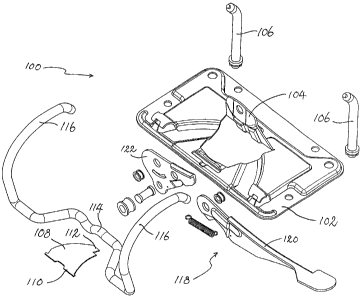
A lever-arch type file mechanism according to a first embodiment of the
present
invention is shown in Figs. 1 to 5, and generally designated as 100. The
mechanism 100 includes a generally flat base 102 with an upstanding wall 104
extending generally perpendicular from the base 102. The wall 104 is
integrally
formed with the base 102, e.g. being stamped and bent out from a same metal
sheet.
Two posts 106 are fixedly engaged with, and are thus not movable relative to,
the
base 102.
A resilient spring leaf 108 has a first side 110 which is engaged with the
base
102, and an opposite second side 112 which acts on an under side of an
intervening
-6-
CA 02604088 2007-09-24
shaped portion 114 between two arch portions 116. A lever assembly 118 is
engaged with the wall 104, the function and purpose of which will be discussed
below.
As shown more clearly in Fig. 6, the lever assembly 118 has an outer arm 120
pivotally engaged with an inner arm 122 about a rivet 124. The outer arm 120
is
also connected with the inner arm 122 via a spring 126. By way of such an
arrangement, the outer arm 120 is swivellable relative to the inner arm 122.
The
inner arm 122 is also pivotally engaged with the wall 104 via a rivet 128,
which
allows the inner arm 122 to swivel relative to the wall 104.
A lower end of the inner arm 122 carries a roller 130 which travels on and
along
the shaped portion 114. In particular, when the lever assembly 118 is in the
upper
stable position as shown in Figs. 2A to 6, the free ends of the posts 106 and
arch
portions 116 mate with each other to form two closed rings extending upwardly
from
the base 102. The lever assembly 118 may be pivoted downwardly to the lower
stable position as shown in Figs. 7A to 10, in which the roller 130 travels to
a trough
portion 132 of the shaped portion 114, allowing the spring leaf 108 (which
exerts an
upward biasing force on an underside of the shaped portion 114) to pivot
upwardly,
and cause the shaped portion 114, and thus the arch portions 116, to pivot
relative to
the base 102 and the posts 106, and in particular away from the posts 106 to
open
the rings. In such a ring-open configuration, pieces of hole-punched paper
(not
shown) may be inserted into or retrieved from the posts 106 and the arch
portions
116.
As shown more clearly in Figs. 7A and 10, the inner arm 122 has a curved slot
134 in which is received a protrusion 136 of the wall 104 for relative sliding
movement, to limit the extent of pivotal movement of the inner arm 122
relative to the
wall 104.
The structure of the lever assembly 118 is shown more clearly in Figs. 11 and
12.
When the lever assembly 118 is to be pivoted upwardly, the outer arm 120 may
be
acted on by a finger of a user to pivot upwardly, until the outer-arm 120
reaches its
upper position in which it acts on an underside of a ledge 138 of the inner
arm 122 to
-7-
CA 02604088 2007-09-24
pivot the inner arm 122 upwardly. On the other hand, when the lever assembly
118
is to be pivoted downwardly, the outer arm 120 may be acted on by a finger of
a user
to pivot downwardly, to also cause the inner arm 122 to pivot downwardly. It
should
be noted that the spring 126 is arranged such that it biases the outer arm 120
towards the stable lower position shown in Figs. 12 and 13B.
The significance of the aforesaid arrangement can best be seen from Fig. 2A,
in
which the dotted line 120a signifies the position of the upper edge of the
outer arm
120 had the outer arm 120 and the inner arm 122 been made of one piece. Thus,
by way of such an arrangement, when the lever assembly 118 is to be pivoted
upwardly from the lower stable position shown in Fig. 7A to the upper stable
position
shown in Fig. 2A, the full length, and thus the full leverage, of the lever
assembly 118
(i.e. including the outer arm 120 and the inner arm 118) can be utilized, thus
facilitating the upward pivoting action. On the other hand, when the lever
assembly
118 is in the upper position, the outer arm 120 will be moved from its upper
position
to remain in its lower position as shown in Fig. 2A by the biasing force of
the spring
126. In this position, when the outer arm 120 is further away from the ring
closer to
it than when the outer arm 120 is in its upper position shown in dotted line,
pieces of
hole-punched paper retained by the rings formed by the posts 106 and arch
portions
116 may be moved freely between the posts 106 and the arch portions 116. It
can
be seen that the outer arm 120 is movable relative to the inner arm 122
without
changing the rings from a ring-closed configuration to a ring-open
configuration or
vice versa. In particular, the relative position between the posts 106 and the
arch
portions 116, and the relative position between the wall 104 and the inner arm
122,
are not changed during movement of the outer arm 120 relative to the inner arm
122.
The file mechanism 100 may be fixedly secured, e.g. by rivets, to a substrate,
e.g. a cardboard (not shown), to form a lever-arch type file.
A lever-arch type file mechanism according to a second embodiment of the
present invention is shown in Figs. 14 to 17D, and generally designated as
200.
The file mechanism 200 is similar in structure to the lever-arch type file
mechanism
100 discussed above. A main difference between the file mechanisms 100 and 200
is that, in a lever assembly 218 of the file mechanism 200, there is no spring
-8-
CA 02604088 2007-09-24
connecting the outer arm 220 and the inner arm 222. Thus, when there is no
upwardly acting force acting on the outer arm 220, and when in the ring-closed
configuration when the lever assembly 218 is in its upper position, the outer
arm 220
will pivot, on its own weight, downwardly from the upper position shown in
Figs. 15A
to 15D to the lower stable position shown in Figs. 16A to 16D. Again, the
outer arm
200 is movable relative to the inner arm 222 without changing (a) the
configuration of
the rings, (b) the relative position between the inner arm 222 and an
upstanding wall
204 of the file mechanism 200, nor (c) the relative position between the inner
arm
222 and the base 202.
A lever-arch type file mechanism according to a third embodiment of the
present
invention is shown in Figs. 18 to 24D, and generally designated as 300. The
file
mechanism 300 is structurally generally similar to the file mechanisms 100,
200
discussed above, with the main difference residing in the lever assembly 318.
As
shown in Fig. 25, the lever assembly 318 includes an outer arm 320 and an
inner
arm 322. The outer arm 320 has, at a first longitudinal end, a generally flat
thumb
plate 340 and, adjacent a second longitudinal end, a stud 342 on a side of a
curved
body 344. The body 344 is received and guided by two claws 346, 348 along a
body 350 of the inner arm 322 for sliding movement relative to the inner arm
322 in a
curve.
Thus, when the file mechanism 300 is in its ring-closed position as shown in
Figs. 19 and 20, the outer arm 320 may be moved relative to the inner arm 322
from
its upper position as shown in Figs. 19 and 20, along a curved locus, to its
lower
stable position as shown in Figs. 21 and 22, in which the outer arm 320 is
further
away from the lower surface 352 of the arch portion 316 forming part of the
ring
close to it. The outer arm 320 is biased towards this lower position by its
own
weight.
A further feature of this file mechanism 300 is shown in Figs. 23A to 24B in
which the file mechanism 300 is shown in its ring-open configuration, and the
lever
assembly 318 is its lower position. The outer arm 320 may be slid from its
upper
extended position as shown in Figs. 23A and 23B, along a curve, to its lower
retracted stable position as shown in Figs. 24A and 24B. The outer arm 320 is
-9-
CA 02604088 2007-09-24
biased towards this lower position by its own weight.
It can be shown in Figs. 26A and 26B that when the lever assembly 318 is in
its
fully extended configuration, the stud 342 carried by the body 344 of the
outer arm
320 abuts the claw 348 of the inner arm 322 to prevent further outward
movement of
the outer arm 320 relative to the inner arm 322. On the other hand, as shown
in
Figs. 27A and 27B, when the lever assembly is in its fully retracted
configuration, a
broadened part 354 of the outer arm 320 abuts the claw 346 to prevent any
further
inward movement of the outer arm 320 relative to the inner arm 322. Such an
arrangement thus limits the extent of outward and inward movement of the outer
arm
320 relative to the inner arm 322.
A lever-arch type file mechanism according to a fourth embodiment of the
present invention is shown in Figs. 28 to 32B, and generally designated as
400.
The file mechanism 400 is structurally very similar to the file mechanism 300
discussed above, with the main difference residing in the lever assembly 418.
Similar to the lever assembly 318 of the file mechanism 300, the lever
assembly
418 also includes an outer arm 420 and an inner arm 422 which are movable
relative
to each other. In particular, when the file mechanism 400 is in its ring-
ciosed
position as shown in Figs. 29A and 29B, the outer arm 420 may be moved
relative to
the inner arm 422 from its upper position as shown in Figs. 29A and 29B in
which
part of the outer arm 420 is above the arch portion 416 forming part of the
ring closer
to it, along a curved locus, to its lower position as shown in Figs. 30A and
30B, in
which the outer arm 420 is below the lower surface 452 of the arch portion
416.
The outer arm 420 is biased towards this lower stable retracted position by
its own
weight.
As further shown in Figs. 31A to 31 B in which the file mechanism 400 is shown
in its ring-open configuration, and the lever assembly 418 is its lower
position, the
outer arm 420 may be slid from its upper extended position as shown in Figs.
31A
and 31 B, along a curved locus, to its lower stable retracted position as
shown in Figs.
32A and 32B. The-outer arm 420 is biased towards this lower stable retracted
position by its own weight.
-10-
CA 02604088 2007-09-24
The structure of the lever assembly 418 is shown more clearly in Figs. 33 to
35B.
As discussed above, the lever assembly 418 has an outer arm 420 and an inner
arm
422. An inner distal end of the outer arm 420 is provided with a claw 446, and
an
outer distal end of the inner arm 422 is provided with a claw 448. When the
inner
arm 422 and the outer arm 420 are duly assembled, and as shown in Figs. 34A
and
34B, when the lever assembly 418 is in its full extended configuration, the
claws 446,
448 abut with each other to prevent any further extension of the lever
assembly 418.
On the other hand, when the lever assembly 418 is in its fully retracted
configuration,
a thickened part 454 of the outer arm 420 abuts the claw 448 to prevent any
further
inward sliding movement of the outer arm 420 relative to the inner arm 422.
A lever-arch type file mechanism according to a fifth embodiment of the
present
invention is shown in Figs. 36 to 40B, and generally designated as 500. The
file
mechanism 500 is structurally very similar to the file mechanism 100 discussed
above, with the main difference residing in the lever assembly 518.
As in the case of the lever assembly 118 discussed in relation to the file
mechanism 100 above, the lever assembly 518 has an outer arm 520 and an inner
arm 522 pivotally engaged with and movable relative to each other about a
rivet 524.
As shown in Fig. 43, a spring 526 is provided between and enclosed by the
outer
arm 520 and inner arm 522 to bias the outer arm 520 and the inner arm 522 to
assume the stable configuration as shown in Fig. 37 to 38B, 41 and 42. Further
views showing the structure and shape of the outer arm 520 are shown in Figs.
44A
to 44D. It should be noted that the inner arm 522 has a ledge 560 which is
received
within a gap 562 on an upper side of the outer arm 520. Such an arrangement to
limit the extent of pivotal movement between the outer arm 520 and the inner
arm
522.
A lever-arch type file mechanism according to a sixth embodiment of the
present
invention is shown in Figs. 45 to 49B, and generally designated as 600. This
file
mechanism 600 is structurally similar to the file mechanism 100 discussed
above,
with the major difference being that, in the lever assembly 618 of the file
mechanism
600, there are two outer arms 620a, 620b pivotally engaged with a common inner
-11-
CA 02604088 2007-09-24
arm 622.
When the file mechanism 600 is in the ring-closed configuration, as shown in
Figs. 46 to 47B, the outer arm 620a is generally upwardly extending, and the
outer
arm 620b is generally downwardly extending. The outer arm 620a may be pivoted
downwardly to open the rings, or the outer arm 620b may be pivoted upwardly to
the
open the rings, to assume the ring-open configuration as shown in Figs. 48 to
49B.
Similarly, when the file mechanism 600 is in the ring-open configuration as
shown in
Figs. 48 to 49B, the outer arm 620a may be pivoted upwardly, or the outer arm
620b
may be pivoted downwardly, to close the rings, to assume the ring-closed
configuration as shown in Figs. 46 to 47B.
As shown more clearly in Figs. 50 to 52D, each of the outer arms 620a, 620b is
pivotally engaged with the inner arm 622 via a respective spring 626a, 626b,
which
bias the respective outer arms 620a, 620b towards a lowered stable position,
for
example, as in the relative position between the outer arm 620a and the inner
arm
622 shown in Fig. 52A.
A lever-arch type file mechanism according to a seventh embodiment of the
present invention is shown in Figs. 53 to 57B, and generally designated as
700.
The structure of the file mechanism 700 is very similar to that of the file
mechanism
500 discussed above. As shown in Fig. 58, a lever assembly 718 of the file
mechanism 700 has an outer arm 720 and an inner arm 722 pivotally engaged with
and movable relative to each other about a rivet 724. A spring 726 is provided
between and enclosed by the outer arm 720 and inner arm 722 to bias the outer
arm
720 and the inner arm 722 to assume the stable configuration as shown in Fig.
54 to
55B, 59 and 60. Further views showing the structure and shape of the outer arm
720 are shown in Figs. 63A to 63D. The outer arm 720 may be moved relative to
the inner arm 722 against the biasing force of the spring 726 to assume the
fully
extended configuration shown in Figs. 56 to 57B, 61 and 62. It can be seen
that the
inner arm 722 is planar and the outer arm 720 has a continuous bent upper edge
740 which covers at least part of the upper edge 742 of the inner arm 722.
It should be understood that the above only illustrates examples whereby the
-12-
CA 02604088 2007-09-24
present invention may be carried out, and that various modifications and/or
alterations may be made thereto without departing from the spirit of the
invention.
It should also be understood that certain features of the invention, which
are, for
clarity, described in the context of separate embodiments, may be provided in
combination in a single embodiment. Conversely, various features of the
invention
which are, for brevity, described in the context of a single embodiment, may
also be
provided separately or in any appropriate sub-combinations.
-13-