Note: Descriptions are shown in the official language in which they were submitted.
CA 02604102 2007-10-09
WO 2006/127188 PCT/US2006/014901
IMPROVED MAIN TEE CONNECTION
BACKGROUND OF THE INVENTION
The invention relates to suspended ceiling grid and more particularly,
to improvements in splice connections for main runners for such systems.
PRIOR ART
Suspended ceiling grid customarily comprises main runners and cross
runners that intersect the main runners. The main runners are produced in
fixed lengths, typically in 12 foot lengths, and are spliced end-to-end to
extend
across a room. For connecting their ends, current grid tee or runner products
commonly utilize an integral splice or connector cut and ,formed from the grid
runner web material. The splice uses a lanced pocket pushed out from the
vertical web plane in one direction and a protruding stiffened tongue with a
locking detent pushed out in the opposite direction. Upon installation, the
tongue of each runner or tee inserts into an opposing pocket making a double
lock. When all of the physical features of the splice are formed in the ideal
or
desired configuration and location, the tees interlock with a light
predictable
insertion pressure, aligned both vertically and horizontally with each other.
The resultant connection adequately resists pull-apart forces. The geometry
of various physical features, however, tends to vary positionally with
variations
or change in material thickness of the tee material requiring repeated tooling
adjustments as necessary to achieve acceptable part function. Complaints of
hard splice assembly and face misalignment are the result of compromise in
ordinary variation in the supply of material, tool wear, and sometimes a lack
of
constant vigilance at the point of manufacture.
SUMMARY OF THE INVENTION
The invention provides a splice connection for main runners or tees
comprising an end assembly with a uniquely formed pocket made in a cavity
between the central web of the runner and a separate spring steel clip
attached to the web to align and interlock with an identical opposed end
assembly. The result is an in-line connection for main runners or tees.
Because the disclosed pocket is formed by the cavity created between an
CA 02604102 2007-10-09
WO 2006/127188 PCT/US2006/014901
embossed recess on one side of the tee web and an inside clip surface, the
pocket can be made with a fixed width, regardless of variations in material
thickness of the tee itself. The disclosed concept enables a connection to
exhibit consistent insertion pressure as a result of the fixed geometry of the
tee cavity and the resilient nature of the clip and web assembly.
The disclosed clip is configured to connect directly with an identical clip
so that a reliable high strength joint is produced independent of any
variation
in the properties of the material of the tee. The clip and pocket are
configured
to initially self-align the ends of the runners being joined and, when finally
connected, to accurately register the butted ends of the runners.
BRIEF DESCRIPTION OF THE DRAWINGS
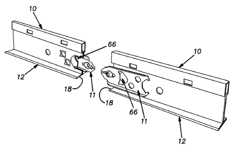
FIG. 1 is a fragmentary perspective view of the ends of two grid
runners prior to being joined;
FIG. 2 is a side elevational view of an end clip embodying the
invention;
FIG. 3 is a longitudinal cross-sectional view of the clip taken in the
plane 3-3 indicated in FIG. 2;
FIG. 4 is a cross-sectional view of the clip taken in a vertical plane 4-4
indicated in FIG. 2;
FIG. 5 is a cross-sectional view of the clip taken in the staggered
planes indicated by the lines 5-5 in FIG. 2;
FIG. 6 is a showing of the clip of the invention after being progressively
stamped but prior to being separated from a continuous strip of successively
stamped clips;
FIG. 7 is a side elevational view of an end portion of a grid runner;
FIG. 8 is a cross-sectional view of the web of the grid runner of FIG. 7
taken in the staggered plane indicated by the lines 8-8;
FIG. 9 is an end elevational view of the grid runner of FIG. 7;
FIG. 10 is a cross-sectional view taken in a horizontal plane of the end
portions of a pair of butted grid runners and associated coupled connector
clips;
2
CA 02604102 2007-10-09
WO 2006/127188 PCT/US2006/014901
FIG. 11 is a fragmentary side elevational view of two grid runners being
assembled with a lead-end portion of one connector clip being guided into
vertical registration with an opposing grid runner by contact of the right
hand
clip with the flange of the left hand grid runner; and
FIG. 12 is a view similar to FIG. 11 with the ends of the runners further
advanced towards abutting contact and the right-hand clip still bearing on the
flange of the left-hand grid runner to vertically align the grid runners.
DESCRIPTION OF THE PREFERRED EMBODIMENT
A main runner or grid tee 10 is assembled at each of its longitudinal
ends with a connector clip 11. The illustrated grid tees 10 are generally
conventional in construction having a lower flange 12, a web 13 extending
vertically upwardly from the center of the flange, and a hollow reinforcing
bulb
14 at the upper edge of the web. In a conventional manner, the tee 10 can be
made by roll forming continuous strips of mild steel sheet stock so that the
bulb 14 has a single wall and the web 13 is formed by two layers of sheet
stock and the flange 12 has two portions 16. The flange portions 16 are
retained together and concealed from a view below by a cap strip 17 of sheet
metal, as is conventional. The roll formed stock is cut into tees of
predetermined length, for example, nominally 12 feet. The opposite ends of
the tees are cut so that its edges 18 at the flange 12 are perpendicular to
the
longitudinal direction of the tee and the edges of the web 13 and bulb 14 can
be formed in a plane tilted slightly rearwardly (e.g. 1 to 3 degrees) away
from
a vertical plane through the flange edge 18. This slight rearward tilt assures
that upon assembly with a mating tee, the respective flange edges 18 will
form a tight butt joint for a good appearance. When describing the tees 10
and clips 11 herein, the forward direction is a direction away from the center
of a tee and, when reference is made to a standard tee, the flanges 12 are, as
mentioned, at the lower edge of the vertical web consistent with the
orientation of the tee in a normal installed condition.
Each end of a tee 10 has its web 13 pierced with a notch 21 open at an
edge 22 of the web. Rearward of the web edge 22, a portion of the web 13 is
formed or stamped with a lateral offset or embossment 23 that includes a
3
CA 02604102 2007-10-09
WO 2006/127188 PCT/US2006/014901
cantilever tab 24. The tab 24 is free of connection with surrounding areas of
the web in a zone forward of its connection with the remainder of the
embossment 23. Apart from the embossment 23, including the tab 24, the
material of the web 13 surrounding the notch 21 remains in the original plane
of the web 13. Lower and upper edges 26, 27 of the notch 21 are spaced
from the flange portion 16 and bulb 14 a substantial distance preferably, for
example, a distance at least several times the thickness of the stock forming
the tee thereby enabling the tooling that creates the notch to be robust in
this
area for long tool life. Two holes 28 are punched through the web 13 to
receive parts of the clip 11 for their permanent assembly as described below.
The clip 11 is stamped from sheet metal stock preferably in strip form
processed in progressive dies or tooling in which various features or
formations are made on the clip body. The clip 11, preferably, is formed of a
high strength spring steel such as Martinsite -130 having a thickness by way
of example of .020 inch. The clip material is thus substantially harder than
the
mild steel material of the tee 10.
The clip 11 has an elongated form with an inner face 31 adapted to
abut the web 13 and an opposite outer face 32. The clip 11 includes stiffening
or reinforcing flanges 33, 34 at its top and bottom edges projecting outwardly
from the outer face 32. The clip 11 is lanced and formed at two locations 36
to form integral projections 37 that after being inserted in corresponding
holes
28 in the tee web 13 are staked or clinched in the manner of a rivet to
permanently assemble the clip 11 to the grid tee 10. The areas of the clip 11
surrounding the projections 37 is planar and, for reference purposes, can be
considered to be the plane of the clip body or clip proper. Apart from the
projections 37, the clip 11 is bilaterally symmetrical about a longitudinal
medial plane.
A central major polygonal or chevron-shaped hole 39 through the clip
11 has at its upper and lower regions, a pair of opposed flanges 41 bent out
of
the plane of the clip. The flanges or tabs 41 as seen in FIG. 4 are bent out
of
the clip plane by more than 90 degrees so that they converge towards one
another with increasing proximity to the plane of the clip. On its forward
side,
the hole 39 is bounded by a rearwardly facing edge surface 42. Forward of
4
CA 02604102 2007-10-09
WO 2006/127188 PCT/US2006/014901
the major hole 39, in succession, are a minor round hole 44 and a square hole
46. The round hole 44 is centered on an imaginary vertical line through the
end edge 18 of a runner flange when the clip is assembled on the runner. A
triangular depression 47 formed in the inner face or side 31 of the clip
opposite the side seen in FIG. 2 bridges the area between the minor holes 44,
46. A lateral projection 48, centered on the imaginary center line or medial
plane of a clip 11 is formed on the clip inner face forward of the square hole
46. The projection 48 has a cam surface 49 that tapers laterally away from
surrounding areas of the clip from a forward portion 50 rearwardly to a
rearwardly facing locking edge surface 51 that forms part of the hole 46. A
small spherical projection 52 is formed on the outer side of the clip 11
longitudinally between the projection 48 and a lead edge 53 of the clip 11.
The lead edge 53 has a vertical portion 54 and lower and upper inclined
portions 56, 57, respectively, trailing the vertical portion 54.
FIG. 6 shows that the forward tapered end of a clip bounded by the
lead edge portions 54, 56, 57 nests within a V-shaped notch 58 pierced in a
rearward part of a preceding clip made in progressive stamping equipment.
This technique produces a clip 11 that is considerably longer than the
effective length of stock used per clip. The extended length of the clip 11
enhances its stability when assembled on the tee 10.
The lead edge portions 56, 57 extend to horizontal edges 59 spaced a
predetermined distance from one another. Rearward of the horizontal edges
59, are inclined surfaces 61, 62 formed by extensions of the clip flanges 33,
34.
The body of the clip 11 forward of the major hole 39 between horizontal
bend lines indicated at 63, 64, extended from the edge portions 59 and
surrounding the projections 52 and 48 and recess or depression 47, is planar
and bent slightly laterally, from the plane of the clip body rearward of the
major hole 39, to the side to which the projection 48 extends (FIG. 3).
The geometry of the clip 11 and formations on the end of the tee 10 are
arranged to connect with an identical clip, or a similar clip, and a tee end
with
features described above in the manner of a handshake. Therefore, as is
customary, the tee 10 has identical or essentially the same clips on each of
its
5
CA 02604102 2007-10-09
WO 2006/127188 PCT/US2006/014901
ends. Tees are connected end-to-end by roughly aligning them end-to-end
and pushing their clips into the pockets 66 formed between the inside of the
web embossment 23 and the related clip 11 of the opposed tee end. The
initial alignment need not be perfect since the tapered nose of the connector
formed by the surfaces 56, 57 and 61, 62 is adapted to guide or cam the clips
into vertical alignment. Lateral alignment is initially accomplished by simply
abutting the clips laterally or side-by-side. If the clip 11 of the tee being
installed is simply laid onto the top of the flange portion 16 of the
previously
installed tee, with the clip abutting the correct side of the clip on the
previously
installed tee, the lower inclined edges or surfaces 56, 61 of the clip being
installed will cam the clip vertically upward when it is pushed longitudinally
against the opposing tee. This camming action is depicted in FIGS. 11 and
12 where the surfaces 56 and 61 engage the forward edge of a flange portion
16 of an opposing previously installed tee 10. The spherical projection 52
prevents the lead edge 53 of the clip being forced into a pocket 66 from
cutting into the surface of the opposing tab 24 or rearward part of the
embossment 23, typically of a softer material than a clip. The angular or
oblique orientation of the receiving tab 24 and associated embossment 23,
urges the installing clip laterally towards the plane of the web 13 of the
receiving tee. Towards the end of the insertion motion, the flanges or tabs 41
of a receiving clip 11 register with the parallel edges 59 of the clip being
inserted to closely vertically register the clips together. The converging
distance between the flanges 41 avoids any unnecessarily tight fit between
the edges 59 of an installing clip and the flanges of a receiving clip until
the
clips are very nearly fully connected. When the clip being installed is
longitudinally fully advanced relative to the receiving clip, the rearwardly
facing edge surface or locking edge 51 of the projection 48 snaps into the
major hole of the mating clip and locks against this hole edge. This snap
action produces audible and tactile signals to the installer that the
connection
is completed. Prior to the last increment of assembly motion, the recess or
depression 47 can reduce interference between this area and the advancing
projection 52 and can assist in vertically aligning the clips by vertically
guiding
the advancing projection. The tapered profile of the lead edge 53 of the clip,
6
CA 02604102 2007-10-09
WO 2006/127188 PCT/US2006/014901
the geometry of the flanges 41 and pocket 66 prevent the mating clips from
connecting if the clips, and.their runners are vertically misaligned.
The clips 11 can be precisely formed from a sheet metal strip since the
stock can be held to exacting thickness tolerances while being reasonably
economical due to its relatively small size compared to the volume of material
comprising the grid tee proper. The pocket 66 formed between the
embossment 23 including the tab 24 and the inside surface of the clip 10 does
not vary in width despite regularly experienced variations in the thickness of
the tee material stock. Variation in the width of the pocket 66 is avoided
because the tab 24 and associated embossment 23 can be readily stamped
by tooling with a lateral offset from the plane of the tee web by a fixed
predetermined amount regardless of the thickness of the tee material stock.
Consistent lateral sizing of the pocket 66 ensures that only a low consistent
force is required to establish a full connection between a pair of tees. The
connection between abutted tees is quite strong, because the locking
surfaces are part of the clips and, therefore, have very high yield strength.
With a pair'of clips 11 coupled to one another their respective round holes 44
are in alignment and a screw or other fastener can be inserted through these
holes where an exceptionally strong joint is required.
A coupled pair of grid tees can be conveniently disconnected without
tools by simply twisting one of the coupled tees about its longitudinal axis.
This twisting action results in resilient deflection of the tabs 24,
embossments
23 and clips to a degree sufficient to enable the locking edges 51 to move
laterally out of engagement with the receiving edge 42 of the main hole 39 of
the opposing clip to thereby release their locking engagement. This resilient
deflection is permitted by the geometry of the related embossment and tab on
the web and the absence of direct affixing of the clip to the web forward of
the
locking edge of the major hole in the web.
The flat angled portion of the clip between the lines 63, 64 at the
forward end of the clip that is angled relative to the plane of the clip at
the rear
acts when connected to another clip to "sandwich" or force the tee web above
and below the notched forward web area into planar alignment with another
connected tee regardless of the tee material thickness.
7
CA 02604102 2007-10-09
WO 2006/127188 PCT/US2006/014901
It should be evident that this disclosure is by way of example and that
various changes may be made by adding, modifying or eliminating details
without departing from the fair scope of the teaching contained in this
disclosure. The invention is therefore not limited to particular details of
this
disclosure except to the extent that the following claims are necessarily so
limited.
8