Note: Descriptions are shown in the official language in which they were submitted.
CA 02604112 2007-09-24
-1-
TITLE: ADIPOSE RESOLVE APPARATUS FOR LOW-POWER LASER
TECHNICAL FIELD
The present invention relates to low-power laser irradiation of skin surfaces
for
lipolysis of underlying adipose cells. More particularly, this invention
relates to low-
power laser applicators, systems comprising the laser applicators, and methods
for their
use in providing lipolysis treatments.
BACKGROUND OF THE INVENTION
Various apparatuses are known for providing a curative effect by irradiating
spots
on a patient's body with low-power insertable laser devices. Such apparatus
are generally
configured with one or more laser diodes configured for emitting outputs in
the range of
5mW to lOmW and wavelengths in the range of 635nm to 650nm, and a low power
laser
diode driver for arbitrarily adjusting the amount of laser beam emitted from
the on or
more laser diodes.
For example, Korean Utility Model No. 302173 discloses an electric mat for
uniformly emitting a laser beam through a low power laser diode. Korean
Utility Model
No. 270882 discloses a waist belt including a laser generator having a laser
diode for
emitting laser light having a wavelength of 580 - 980nm to stimulate the
lumbar, thereby
performing finger-pressure treatment and therefore medical treatment of a
disc. Korean
Utility Model No. 274266 discloses a laser for medical treatment and an LED
blanket
capable of widening a curative range, for example, irradiation of spots on the
body
suitable for acupuncture, chronic article rheumatism, frozen shoulder,
lumbago, cervical
vertebral sprain, gout, wrench, bruising, arthritis, stress gastritis, and so
on. Korean
Patent No. 457964, issued to the present applicant, discloses a laser beam
radiator
capable of non-invasively irradiating blood in a blood vessel with a laser
beam according
to a position and a thickness of the blood vessel by adjusting a distance of
the laser beam
condensed through an optical lens, activating metabolism of a cell by
stimulating a blood
cell using a laser beam, increasing formation of capillary vessels to improve
blood
circulation, and increasing speed of tissue treatment to activate living
organisms.
DM VAN/253729-16266/6739700.1
CA 02604112 2007-09-24
-2-
While another laser apparatus using a laser beam disposed in an array for
providing use convenience is proposed to be adapted to various soft materials
such as a
chair, a hat, a bed, a belt, and so on, when the laser beam is disposed in the
soft materials
in an array, a red laser capable of being output appropriately to non-
invasively break
down fat (about, more than 30mW) should be used. However, since the red laser
requires
a separate radiation structure, there is no way of breaking down fat by non-
invasively
irradiating a human body.
Meanwhile, in order to effectively treat obesity using a laser, Neira et al.
(2002,
Plastic and Reconstructive Surgery 110(3): 912-922) disclose a process for
liquefying fat
by waving a low-power laser back and forth six inches above a subject's
abdomen and
then removing the liquefied fat with a surgical liposuction i.e., lipectomy
procedure.
Neira et al.'s paper is based on a test in which lasers having a wavelength of
635nm, an
output of 10mW, and a total energy of 1.2J/cm2, 2.4J/cm2 and 3.6J/cm2 are
radiated onto
adipose tissue extracted from 12 healthy women. As a result of the test, 4
minutes after
laser exposure, 80% of the fat in the adipose cells is discharged, and 6
minutes after the
laser exposure, 99% is discharged. It was reported that energy of the low
power laser acts
to open a cell wall to discharge fat from the interior to the exterior of the
adipose cell.
Then, the discharged fat is gathered in a space between the adipose tissues.
Using the fat
liquefaction effect of the red laser on the basis of the test, suction
lipectomy using a laser,
in which the human body is irradiated from outside to break down fat and
discharge the
broken down fat from the body using a cannular (fine pipe), has been proposed.
Various methods of non-invasively irradiating skin covering a fatty area of a
treatment target with a red laser beam to break down the fat of the adipose
cells have
been attempted. In order to irradiate a wider area for a short time, a device
for forming a
red laser beam with a line shape to scan the treatment target has been
developed and put
on the market. However, it is difficult to input a power of 10mW and an energy
density
of 3.6J/cm2 required for lipolysis in the human body, thereby obtaining little
practical
effect.
DM VAN/253729-I6266/6739700.1
CA 02604112 2007-09-24
-3-
SUMMARY OF THE INVENTION:
The exemplary embodiments of the present invention are directed to laser
applicators, systems comprising the laser applicators, and methods for their
use for
liquefaction of fats in adipose cells for removal into interstitial spaces
wherefrom they are
removed from a subject's body by their normal physiological processes.
According to one exemplary embodiment, there is provided a laser applicator
having at least one low-power light-emitting laser diode. A suitable low-power
light-
emitting laser diode is one that emits power outputs in the range comprising
about 10mW
to about 100mW with light waves in the range of 635nm to 680 nm. The laser
applicator
is configured for contacting a subject's body surface for application of low-
power laser
irradiation. The laser applicator is configured to communicate and cooperate
with a laser
control device comprising a power supply device, circuitry interconnecting
software-
controllable electronic devices configured for at least one of generating,
transmitting,
recording, processing, storing and reporting electronic signals useful for
manipulable
modulation of the output from the power supply device for generation of laser
light
waves. The low-power laser irradiation causes liquefaction of fats in adipose
cells in the
subcutaneous portions of the subject's body underlying the surface contacted
by the laser
applicator. The liquefied fat is discharged from the adipose cells into the
interstitial areas
between the cells from which it is absorbed by the subject's lymphatic system
and
removed from their body with their normal physiological processes.
According to one aspect, the laser applicator comprises a plurality of low-
power
light-emitting diodes.
According to another aspect, the laser applicator is provided with a plurality
of
low-power light-emitting diodes each selected for emission of power outputs in
the range
comprising about 10mW to about 100mW with light waves in the range of 635nm to
680
nm, and a plurality of medium power laser diodes having power outputs in the
range of
about 80mW to about 160mW with light waves in the range of 780nm to 980 nm.
According to another aspect, the laser applicator comprises a printed circuit
board
DM VAN/253729-16266/6739700.1
CA 02604112 2007-09-24
-4-
provided with a power connector for communicating with a controller device, a
contact
plate formed of a hard plate configured for cooperating with the PCB and
having at least
one transparent window or a lens disposed at one side surface, at least on low-
power
light-emitting laser diode inserted into the at least one transparent window
or lens
disposed on the contact plate and electrically connected to the PCB; and a
framework or
alternatively, a housing for accommodating and retaining therein the laser
printed circuit
board, contact plate and laser diode. The housing is suitable configured for
contacting the
at least one transparent window or lens of the contact plate in close contact
with the skin
during application of laser irradiation of the skin and underlying
subcutaneous region.
According to a further aspect, the contact plate may comprise a flexible
material.
According to a yet further aspect, a plate of heat-absorbing material may be
interposed the contact plate and the printed circuit board. The plate of heat-
absorbing
material may be configured to communicate and cooperate with a cooling device.
According to another aspect, the surface of the contact plate may be coated
with a
thermal interface material.
According to another exemplary embodiment of the present invention, there is
provided a lipolysis system comprising at least one laser applicator provided
with at least
one low-power laser diode selected for emission of power outputs in the range
comprising about 10mW to about 100mW with light waves in the range of 635nm to
680
nm, and a laser control device provided with hardware, circuitry and software
configured
for at least one of generating, transmitting, recording, processing, storing
and reporting
electronic signals useful for manipulable modulation of the output from the
power supply
device for generation of laser light waves. The at least one applicator is
configured for
contacting a portion of a subject's body surface for controllably and
manipulably
providing laser light irradiation thereto for the purpose of liquefying fats
in adipose cells
in the subcutaneous region underlying the portion of the subject's body
surfaces
contacted by the laser applicator.
According to one aspect, the laser applicator is provided with a plurality of
low-
DM VAN/253729-16266/6739700.1
CA 02604112 2007-09-24
-5-
power laser diodes each selected for emission of power outputs in the range
comprising
about 10mW to about 100mW with light waves in the range of 635nm to 680 nm.
According to another aspect, the laser applicator is provided with a plurality
of
low-power light-emitting diodes each selected for emission of power outputs in
the range
comprising about 10mW to about 100mW with light waves in the range of 635nm to
680
nm, and a plurality of medium-power laser diodes each having power outputs in
the range
of about 80mW to about 160mW with light waves in the range of 780nm to 980 nm.
According to another aspect, the laser applicator housing may be configured to
contact a larger portion of a subject's body surface such as an abdomen, the
lower back
area, hips, and buttocks. The housing and contact plate provided in this
embodiment are
suitably concave. The contact plate may optionally comprise a flexible
material.
According to yet another aspect, the laser applicator housing or alternatively
the
framework, may be provided with hinges on its opposite ends thereby making it
possible
to interlink two or more such hinged laser applicators together. Accordingly,
the two or
more interlinked laser applicators may be controllably maneuvered to provide
excellent
contact of larger portions of a subject's body surface with the contact plates
having
disposed therein laser diodes.
According to another exemplary embodiment of the present invention, there are
provided methods for the use of the lipolysis systems of the present invention
for
liquefying fats in subcutaneous adipose cells. An operator contacts the
contact plate of
the at least one laser applicator with a target portion of a subject's body
surface after
which the operator manipulates the control device to provide laser light
irradiation of the
target portion of the subject's body portion for a selected period of time
during which the
laser light causes liquefaction of fats in adipose cells in the subcutaneous
region
underlying the target body portion. The liquefied fats are discharged from the
adipose
cells into the interstitial spaces wherefrom the liquified fats are removed
from the
subcutaneous regions underlying the target portions by the subject's lymphatic
system. It
is suitable during a lipolysis treatment session to contact the at least one
laser applicator
DM VAN/253729-16266/6739700.1
CA 02604112 2007-09-24
-6-
with multiple target portions of a subject's body surface for application of
laser
irradiation thereto.
According to another exemplary embodiment of the present invention, there is
provided a vacuum suction device configured to sealably engage and cooperate
therewith
a laser applicator of the present invention. The vacuum suction device is
suitably
configured with an inner bowl-shaped chamber having an outer rim configured
for
sealingly engaging a target portion of a subject's body surface. The apex of
the bowl-
shaped chamber is configured to sealingly engage and communicate with the
contact
plate of the laser applicator, and to transmit therethrough laser irradiation
generated by
the at least one laser diode of the laser applicator. The vacuum suction
device is
interconnected to a controllable vacuum pump.
According to one aspect, the vacuum suction device is configured to sealingly
engage and cooperate with a laser-generating device comprising a low-power
laser diode
selected for emission of power outputs in the range comprising about 10mW to
about
100mW with light waves in the range of 635nm to 680 nm.
According to another aspect, the vacuum suction device is provided with at
least
one pressure release aperture configured for engagement and disengagement by
an
operator's finger.
According to another exemplary embodiment of the present invention, there is
provided a lipolaser system comprising a vaccum suction device configured to
cooperate
with a laser applicator of the present invention or alternatively with a laser
generating
device, an exemplary laser applicator of present invention or alternatively a
laser
generating device, and a controllable vacuum pump cooperatively interconnected
to the
vacuum suction device.
According to one aspect, the vacuum pump is controllably and manipulably
interconnected to a plurality of vacuum suction devices.
According to another exemplary embodiment, there are provided methods for the
provided methods for the use of the lipolysis systems comprising the vacuum
suction
devices of the present invention for liquefying fats in subcutaneous adipose
cells. An
DM VAN/253729-16266/6739700.I
CA 02604112 2007-09-24
-7-
operator contacts the outer rim of the vacuum suction device with a target
portion of a
subject's body surface after which the operator activates the vacuum pump and
manipulates the laser control device to provide laser light irradiation of the
target portion
of the subject's body portion for a selected period of time during which the
laser light
causes liquefaction of fats in adipose cells in the subcutaneous region
underlying the
target body portion. The liquefied fats are discharged from the adipose cells
into the
interstitial spaces wherefrom the liquified fats are removed from the
subcutaneous
regions underlying the target portions by the subject's lymphatic system. It
is suitable
during a lipolysis treatment session to contact the at least one laser
applicator with
multiple target portions of a subject's body surface for application of laser
irradiation
thereto.
According to one aspect, an operator may impose and release suction force
within
the vacuum suction device by engaging and disengaging the pressure release
aperture
with their finger. The vacuum suction device may be moved about a subject's
body
surface while the pressure release aperture is disengaged.
According to another exemplary embodiment of the present invention, there are
provided lipolysis systems comprising at least one first laser applicator
provided with a
plurality of low-power laser diodes and configured to contact a portion of a
subject's
body surface for providing laser irradiation thereto, at least one second
laser applicator
provided with at least one lower power laser diode and configured to contact a
portion of
a subjects body surface for providing laser irradiation thereto, and a laser
control device
configured for controllably communicating and cooperating with first and
second laser
applicators.
According to another exemplary embodiment of the present invention, there are
provided methods for the use of the lipolysis systems of the present invention
comprising
at least one first laser applicator provided with a plurality of low-power
laser diodes and
at least one second laser applicator provided with at least one low-power
laser applicator,
for sequentially contacting selected target portions of a subject's body
surface for the
purpose of providing laser irradiation thereto and therethrough to the
underlying
DM_VAN/253729-16266/6739700.1
CA 02604112 2007-09-24
-8-
subcutaneous regions for liquefaction of fats in adipose cells thereabout.
According to one aspect, the methods of use comprise a plurality of sets of
sequential laser irradiations to different targeted regions of a subject's
body surface.
According to another aspect, the methods of use of the lipolysis systems of
the
present system to apply laser irradiations to selected targeted portions of a
subject's body
surface, are combined with the subject mounting and communicating with
physical
exercise equipment during the periods of laser irradiation. Suitable physical
exercise
equipment is exemplified by whole body vibration devices.
According to another aspect, the methods of use of the lipolysis systems of
the
present system to apply laser irradiations to selected targeted portions of a
subject's body
surface are combined with treatments comprising the subcutaneous injection of
compositions configured to at least partially lyse adipose cells located
thereabout,
wherein a subject receives at least one such injection to a target body
portion after which,
at least one low-power laser applicator of an exemplary lipolysis system of
the present
invention is contacted with the target body portion for application of low-
power laser
irradiation thereto.
BRIEF DESCRIPTION OF THE DRAWINGS
The present invention will be described in conjunction with reference to the
following
drawings, in which:
Fig. 1 is an exploded perspective view of a laser applicator of an exemplary
lipolysis system according to one embodiment of the present invention;
Fig. 2 is a plan view of a laser irradiation distribution range of an
exemplary laser
applicator according to another embodiment of the present invention;
Fig. 3 is a perspective view of an exemplary laser applicator system according
to
the present invention;
Fig. 4 is a perspective view of another exemplary laser applicator system
DM_VAN/253729-16266/6739700.1
CA 02604112 2007-09-24
-9-
according to the present invention;
Fig. 5 is a cross-sectional schematic side view of another exemplary laser
applicator system according to the present invention;
Fig. 6 is a cross-sectional side view of another exemplary embodiment of a
laser
applicator system according to the present invention;
Fig. 7 is an exploded perspective view of the embodiment shown in Fig 6;
Fig. 8 is a schematic diagram of an exemplary expanded laser application
system
according to the present invention, comprising a plurality of cooperating
embodiments
exemplified in Figs. 6 and 7;
Fig. 9 is a schematic view of an exemplary lipolysis system provided with a
plurality of two types of laser applicators according to the present
invention;
Fig. 10(a) is a side view of one type of laser applicator of the lipolysis
system
shown in Fig. 9;
Fig 10(b) is an end view of the laser applicator shown in Fig. 10(a);
Fig. 10(c) is a perspective view of the laser applicator shown in Fig. 10(a);
Figs. 11(a)-11(c) are schematic illustrations of exemplary positioning of the
laser
applicators of the lipolysis system shown in Fig. 9, about a subject's body
torso for
liquefaction of fats about their waistline;
Figs. 12(a)-12(c) are schematic illustrations of exemplary positioning of the
laser
applicators about a subject's body torso for liquefaction of fats about their
abdominal
oblique muscle areas;
Figs. 13(a)-13(c) are schematic illustrations of exemplary positioning of the
laser
applicators about a subject's body torso for liquefaction of fats about their
upper
abdominal areas;
DM VAN/253729-16266/6739700.1
CA 02604112 2007-09-24
-10-
Figs. 14(a)-14(d) are schematic illustrations of exemplary positioning of the
laser
applicators about a subject's body torso for liquefaction of fats about their
upper thigh
areas;
Figs. 15(a)-15(d) are schematic illustrations of exemplary positioning of the
laser
applicators about a subject's body torso for liquefaction of fats about their
lower back
areas;
Fig. 16 is a chart showing the average girth loss of subjects receiving
treatments
with an exemplary lipolysis system of the present invention compared with
subjects
receiving a placebo treatment;
Fig. 17 is a chart showing average girth loss receiving treatments with the
exemplary lipolysis system used in Fig 16 during the first, third and eight
treatment
sessions, and their total average girth loss after the third and eight
sessions; and
Fig. 18 is a chart comparing the cumulative results of blinded appearance
ratings
over the eight treatment sessions with the exemplary lipolysis system used in
Fig 16
compared with subjects receiving a placebo treatment.
DETAILED DESCRIPTION OF THE INVENTION
Exemplary embodiments of the present invention provide laser applicators for
contacting and controllably irradiating portions of a subject's body surfaces
with low-
power lasers, systems comprising one or more of the laser applicators
cooperating with a
suitable control devices for controllably generating laser irradiation from
the laser
applicators, and methods for the use of the systems for liquefaction of fat in
adipose cells
underlying the body surfaces for removal from the irradiated portions by the
subject's
physiological processes.
An exemplary laser-applicator 10 of the present invention is illustrated in
Fig. 1.
The laser applicator 10 generally comprises a printed circuit board (PCB) 12
provided
with a power connector 11 for receiving power, and a contact plate 14
configured to
communicate and cooperate with the PCB 12. The contact plate 14 is provided
with one
DM VAN/253729-16266/673970Q I
CA 02604112 2007-09-24
-11-
or more selectively spaced-apart transparent windows or alternatively lenses
13 disposed
on the surface opposite the surface that contacts the PCB 12. One or more
laser diodes 15
are inserted into selected transparent windows or lenses 13 disposed on the
contact plate
14, and is electrically connected to the PCB 12. A plurality of fastening
holes 17a and 17b
are provided at selected locations on the PCB board 12 and the contact plate
14 to enable
securing of the PCB 12 to the contact plate 14 with a plurality of fasteners
16. As shown
in Fig. 1, the laser applicator 10 may be assembled by inserting the laser
diodes 15 into
the transparent windows or lenses 13 of the contact plate 14, then securing
the contact
plate 14 to the PCB 12 with a plurality of the fasteners 16. Although Fig. 1
shows the
laser applicator 10 configured with four laser diodes 15, it is within the
scope of this
invention to provide laser applicators having one laser diode or
alternatively, a selectable
plurality of laser diodes. The laser applicator 10 is interconnectable through
the power
connector 11 to a laser control device (not shown) comprising a power supply
device,
circuitry interconnecting software-controllable electronic devices configured
for at least
one of generating, transmitting, recording, processing, storing and reporting
electronic
signals useful for manipulable modulation of the output from the power supply
device for
generation of laser light waves.
It is suitable to encase the laser applicator 10 within a housing structure
(not
shown) configured to expose at least the transparent windows or lenses of the
contact
plate 14, and to provide suitable contact for the contact plate 14 with a
subject's body
surface. It is preferable that the housing structure is also configured for
graspability and
ease-of-handling by an operator and for a subject's comfort when the laser
applicator 10
is in contact with a portion of their body surface. Alternatively, as
illustrated in Fig. 2, a
laser applicator according to the present invention may comprise a housing or
framework
30 provided for containing a PCB (not shown) cooperatively assembled with a
contact
plate 14 configured with a large plurality of laser diodes 15.
While the plurality of laser diodes 15 shown in Figs 1 and 2 are uniformly
disposed within the contact plate 14, it is also within the scope of the
present invention to
dispose a selected number of laser diodes 15 in an irregular pattern about the
contact
plate 14. Furthermore, although an elongate contact plate 14 is illustrated in
Figs. 1 and 2,
DM VAN/253729-16266/6739700.1
CA 02604112 2007-09-24
-12-
it is also within the scope of the present invention to provide contact plates
having
alternative shapes such as circular, elliptical, sigmoidal, obround, gibbous
and the like,
configured to enhance the comfort of a subject when the laser applicator 10 is
contacting
a portion of their body surface.
Suitable laser diodes for incorporation into the laser applicators of the
present
invention are capable of producing power outputs in the range comprising about
10mW
to about 100mW with light waves in the range of 635nm to 680 nm, i.e.,
commonly
referred to by those skilled in this art as low-power light-emitting laser
diodes. When one
or more of such low-power laser diodes is/are contacted with a subject's body
surface, the
emitted light waves will penetrate through the epidermal and dermal skin
layers into the
subcutaneous regions which are primarily composed of adipose cells. The energy
of low-
power light waves penetrating into the adipose cells causes liquefaction of
solid and
semi-solid fat deposits contained in the adipose cells. The liquefied fats are
then easily
translocated out of the adipose cells into the interstitial spaces from where
they are
removed by the subject's lymphatic system and discharged from the subject's
body by
their normal physiological processes.
A possible consequence of providing arrays with large pluralities of low-power
laser diodes is that considerable amounts of heat may be generated from the
laser diodes
during prolonged application of laser light energy to a subject's body portion
thereby
causing some discomfort. Therefore, it is within the scope of the present
invention to
provide a plate of heat-absorbing material interposed the contact plate 14 and
the PCB 12
to absorb heat generated by the bases of the low-power laser diodes, and
configured to
disperse the heat toward and from the rear of the laser applicator.
Alternatively, the plate
of heat absorbing material may be configured to communicate and cooperate with
a
cooling device for controllably removing heat generated by the low-power laser
diodes
while cooling the contact plate 14. Alternatively, the surface of the contact
plate 14
opposite the PCB board 12 may be coated with a thermal interface material.
It is particularly useful to configure a laser applicator comprising at least
one
extended array of closely placed together plurality of low-power laser diodes
for
DM VAN/253729-16266/673y700.1
CA 02604112 2007-09-24
- 13-
contacting a subject's body surface thereby enabling the irradiation of larger
surface
areas. The consequence is a more uniform irradiation of larger areas of
adipose cells
resulting in more substantial amounts of fat liquefaction and removal from the
body
portions contacted by the laser applicator, thus making it possible to
selectively reduce
the extent of fat-induced protuberances about a subject's body. Fig. 3
illustrates another
exemplary laser applicator 50 provided with a concave contact plate 54 fitted
into
concave curvilinear framework 56 configured to at least partially encircle
larger areas of
a subject's body such as the abdomen, lower hips, buttocks, and upper thigh
areas. The
opposite ends of the framework 56 are provided with handles 57, to enable easy
handling
and positioning of the laser applicator 50 about the subject's body portions
by an
operator. For such laser applicators, it is suitable for the contact plate 54
to comprise a
flexible material that is capable of conforming to the contours of the
subject's body
portions onto which the laser applicator is positioned. Alternatively, the
contact plate 54
may comprise a stiff material that may be molded into a selected configuration
suitable
for application only to a selected target body portion. The exemplary laser
applicator 50
illustrated in Fig.3 may be placed and positioned by an operator onto a
subject who is in a
prone position lying on their back or alternatively, on their stomach.
However, it is
optional to provide a vertical support 59 fitted with a vertically adjustable
positioning
device 58 configured to engage the laser applicator 50. The subject can then
in a standing
position contact a selected body portion with the laser applicator 50 after
the positioning
device 58 has been adjusted to provide optional contact between the subject's
body
portion and the laser applicator 10. Those skilled in these arts will
understand that the
vertically adjustable positioning device 58 may be optionally provided with a
pivoting
component (not shown) for enabling the rotation of the laser applicator from a
horizontal
plane to a vertical plane. It is also within the scope of the present
invention to incorporate
a laser control device components into the positioning device 58.
Fig. 4 is a perspective view of an alternative embodiment of a laser
applicator 60
comprising three interconnected hinged sections 66, 66', 66" that can be
adjusted to
encompass larger portions of a subject's body surface regardless of the extent
of
protuberations caused by excessive accumulations of solid and semi-solid fats
in the
adipose cells underlying the larger portions of the body surface. In this
exemplary
DM VAN/253729-16266/6739700.1
CA 02604112 2007-09-24
-14-
embodiment, a primary section 66 comprising a housing fitted with a flat
elongate contact
plate 64 having a plurality of laser diodes 65, is provided with a hinge 62
disposed at
each of its opposite ends. A first secondary section 66' is fitted with a flat
contact plate
64' having a plurality of laser diodes 65', and has one end configured for
hinged
communication and cooperation with a first hinge 62. A second secondary
section 66"
also fitted with a flat contact plate (not visible in this view) having a
plurality of laser
diodes (not visible in this view), has one end configured for hinged
communication and
cooperation with the other hinge 62'. It is suitable for the first and second
secondary
sections 66' and 66" to be provided with handles 67 on the ends opposite their
hinged
ends. The hinges 62, 62' enable pivotable adjustment of the first and second
secondary
sections 66', 66" about the primary section 66 thus enabling an operator to
fit the laser
applicator 60 to a subject's body portion while they are lying in a prone
position on a
suitable support, and thereby provide excellent contact between each of the
hinged
sections 66, 66', 66" and the body portion regardless of the contours and
extent of
protuberations caused by excessive solid and semi-solid fat content in the
underlying
adipose cells. Consequently, the application of low-power laser irradiation to
a subject's
body portion by this embodiment of the laser applicator of the present
invention will
provide exceptional liquefaction of the solid and semi-solid fat content in
the underlying
adipose cells. Although Fig. 4 illustrates that the three hinged sections 66,
66', 66" are
rectangular, is within the scope of the present invention to provide various
suitable shapes
such as circular, elliptical, sigmoidal, obround, gibbous and the like, that
are hingedly
interconnectable to enhance the comfort of a subject when the laser applicator
60 is
contacting a portion of their body surface. Further more, it is suitable to
provide a
primary section 66 configured with a first shape e.g., rectangular, and
secondary sections
66', 66" configured with one or more other types of shapes. The secondary
sections may
be symmetrically paired or alternatively, asymmetrically paired. It is to be
understood
that effective lipolysis treatments comprising liquefaction of solid and semi-
solid fats in
adipose cells may be provided by a laser applicator comprising a pair of
hingedly
interconnected sections, each section comprising at least a PCB, a contact
plate, a laser
diode, a framework, a suitable housing and cooperating hinge components.
Alternatively,
effective lipolysis treatments may be provided by a laser applicator
comprising more than
DM VAN/253729-1626616739700.1
CA 02604112 2007-09-24
-15-
three hingedly interconnected and sections configured as described above. It
is suitable to
configure one of the sections, e.g. a primary section exemplified in Fig. 4,
for engaging a
vertically adjustable positioning device 68 communicating and cooperating with
a
vertical support 69, to enable able a subject to contact a selected body
portion with the
contact plates while in a standing position. Those skilled in these arts will
understand that
the vertically adjustable positioning device 68 may be optionally provided
with a pivoting
component (not shown) for enabling the rotation of the laser applicator from a
horizontal
plane to a vertical plane. It is also within the scope of the present
invention to incorporate
a laser control device components into the positioning device 68.
The present invention also provides devices configured to cooperate with laser
applicators exemplified in Figs. 1 and 2 to facilitate subcutaneous delivery
of lypolysis
treatments for liquefaction of solid and semi-solid fats in adipose cells. One
such
exemplary device is illustrated in Fig. 5 and is generally configured to
cooperate with
laser applicators such as those exemplified in Figs. 1 and 2, for the
application of
negative suction forces to a portion of a body surface concurrent with laser
irradiation of
the subcutaneous region underlying the body surface. The vacuum suction device
70
comprises a molded cylindrical body 71 defining an inner bowl area 72 and is
provided
with a molded base 73 having an outward-extending receptacle 74 in the apex
region of
the molded body for receiving and sealably retaining therein a laser
applicator 40 for
example as exemplified in Fig. 2 and generally configured with housing into
which are
fitted a PCB, a contact plate, and a plurality of laser diodes each
communicating with a
transparent window or lens provided therefor in the contact plate. The molded
base 73 of
receptacle 74 is provided with ports configured to communicate with the
contact plate's
transparent windows or lens of the laser applicator 40 thereby providing
irradiation routes
for the laser light waves from the laser applicator 40 to the body surface
portion 79
contained within the area defined by the rim 75 of the molded body 71. A
vacuum port 76
communicating with the inner bowl area 72 is provided on the outer surface of
the
molded body 71. The vacuum port 76 is configured to sealing engage a vacuum
line 77
interconnected to a vacuum pump 78.
An exemplary method for the use of the laser applicator 40 in combination with
DM VAN/253729-I6266/6739700.1
CA 02604112 2007-09-24
- 16-
the suction device 70 illustrated in Fig. 5, comprises sealably installing the
laser applicator
40 into the receptacle 74 in the base of the molded bowl 72, then
interconnecting the laser
applicator 40 to a suitable control device (not shown) comprising at least a
power supply
device, circuitry interconnecting software-controllable electronic devices
configured for at
least one of generating, transmitting, recording, processing, storing and
reporting
electronic signals useful for manipulable modulation of the output from the
power supply
device for generation of laser light waves. The suction device 70 is then
placed onto a
subject's body surface portion targeted to receive the lypolysis treatment so
that the entire
rim 75 surface is in contact with the subject's skin. The vacuum pump 78 is
then engaged
thereby applying a suction force through the vacuum line 77 and vacuum port 76
to the
inner bowl area 72. The suction force draws the subject's body surface toward
the base
area 73 of the molded bowl 72 so that it is in close proximity to the laser
diodes of the
laser applicator 40. The laser control device is then manipulably operated to
generate
selected amounts of laser energy from the range of 10mW to 100mW by the laser
diodes
15 for irradiation of the body portion that is drawn by the suction force
within the inner
bowl area 72. The laser irradiation penetrates into the subcutaneous region of
drawn-in
body portion and liquefies solid and semi-solid fats in the adipose cells
therein. The
suction force exerted on the body portion facilitates the movement of the
liquefied fat from
the adipose cells into the interstitial spaces from where it is absorbed into
the lymphatic
system and removed from the body portion by the subject's normal physiological
processes.
Another exemplary laser applicator system according to the present invention
is
illustrated in Figs. 6 and 7 and generally comprises a molded bowl-shaped
suction device
90 configured to releasably engage and cooperate with a low-power generating
laser
module 80. The laser-generating module 80 generally comprises a PCB 81
configured for
receiving power, a low level light-emitting laser diode 82 with a power output
in the
range comprising about 10mW to about 100mW with light waves in the range of
635nm
to 680 nm electrically connected to the PCB 81, a transparent window or lens
83 disposed
adjacent to the laser diode 82, upper and lower fixtures 84 and 85 for
accommodating the
PCB 81, the laser diode 82, and the transparent window or lens 83, which are
detachable
from each other, and a cover 86 installed outside the upper and lower fixtures
84 and 85.
DM VAN/253729-16266/6739700.1
CA 02604112 2007-09-24
-17-
A male-threaded part 84a and a female-threaded part 85a are provided at a
lower
periphery of the upper fixture 84 and an upper periphery of the lower fixture
85 to be
threadedly engaged with each other, a hooking threshold 84b is formed at an
inner
periphery of the upper fixture 84 to be engaged with the PCB 81, and a groove
85b is
formed at a lower periphery of the lower fixture 85 to be engaged with the
transparent
window or lens 83. A selected interval between the laser diode 82 and the
transparent
window or lens 83 can be controllably provided by progressively engaging or
disengaging the male threaded part 84a and the female threaded part 85a formed
at the
upper and lower fixtures 84 and 85. The PCB 81 is connectable to a cable 81a
to receive
power, and an insertion hole 86a for inserting the cable 81a therethrough, is
provided at
an upper part of the cover 86.
The bowl-shaped suction device 90 comprises a body 91 provided with a
continuous outer rim having a molded lip 93. The outward-extending surface
portion of
the molded lip 93 may be optionally provided with a continuous channel 94
configured to
receive and cooperate with a ring 95 comprising a suitable resilient material.
Alternatively, the continuous channe194 may be configured to receive and
cooperate with
a plurality of balls (not shown). A vacuum port 97 communicating with the
inner bowl
area 92 with line 96 is provided on the outer surface of the molded body 91.
The vacuum
port 92 is configured to sealing engage a vacuum line 98 interconnected to a
vacuum
pump 100. An upward extending coupler portion 99 is provided at the apex of
the body
91, with a bore therethrough the molded body 91 for receiving and sealingly
engaging the
laser module 80. In order to sealably engage the suction device 90 and the
laser-
generating module 80, female and male threaded parts 83 and 86b are formed
about the
inner upper section of the bore extending through the upper section of the
coupler portion
99 and an outer periphery of the cover 86. Further, the upper and lower
fixtures 84 and 85
may be formed of a thermal interface material for radiating heat generated
from the laser
diode 82 of the laser-generating module 80. An interval between the laser
diode 82 and
the transparent window or lens 83 can be adjusted by first separating the
cover 86 from
the laser diode 82, then controllably engaging or disengaging the male
threaded part 84a
and the female threaded part 85a formed at the upper and lower fixtures 84 and
85.
DM VAN/253729-16266/6739700.1
CA 02604112 2007-09-24
- 18-
An exemplary method for the use of the laser applicator 80 in combination with
the suction device 90 illustrated in Figs. 6 and 7, comprises sealably
installing the laser-
generating module 80 into the coupler 99 at the apex of the molded body 91,
then
interconnecting the laser generating module 80 to a suitable control device
(not shown)
comprising at least a power supply device, circuitry interconnecting software-
controllable
electronic devices configured for at least one of generating, transmitting,
recording,
processing, storing and reporting electronic signals useful for manipulable
modulation of
the output from the power supply device for generation of laser light waves.
The suction
device 90 is then placed onto a subject's body surface portion targeted to
receive the
lypolysis treatment so that the outward-facing surface of the molded lip 93 is
in contact
with the subject's skin. The vacuum pump is then engaged thereby applying a
suction
force through the vacuum line 96 and vacuum port 97 to the inner bowl area 92.
The
suction force draws the subject's body surface toward the base area of the
molded bowl 91
so that it is in close proximity to the laser diode 82 of the laser-generating
module 80. The
laser control device is then manipulably operated to generate selected amounts
of laser
energy from the range of 10mW to 100mW by the laser diode 82 for irradiation
of the
body portion that is drawn by the suction force within the inner bowl area 92.
The laser
irradiation penetrates into the subcutaneous region of drawn-in body portion
and liquefies
solid and semi-solid fats in the adipose cells therein. The suction force
exerted on the body
portion facilitates the movement of the liquefied fat from the adipose cells
into the
interstitial spaces from where it is absorbed into the lymphatic system and
removed from
the body portion by the subject's normal physiological processes. It is
suitable for an
operator to manipulate the vacuum suction device 90 while it is cooperating
with the laser-
generating module 80, about a subject's body surface working toward the groin
area and/or
the armpit areas, where those skilled in these arts know that a great
abundance of
lymphatic vessels are situated, thereby enhancing removal of the liquefied
fats from the
interstitial areas receiving the lipolysis treatments as described herein.
At least one optional pressure-release aperture 101 may be provided
therethrough
the molded body 91 to enable an operator to exert manipulable manual control
of the
partial release of the suction force generated by the suction device 90 during
operation, by
engaging and disengaging one of their fingers with the pressure-release
aperture 101. The
DM VAN/253729-16266/6739700.1
CA 02604112 2007-09-24
-19-
shape of the pressure-release aperture 101 may be circular, oval, rectangular
and suitably
sized. The pressure-release aperture 101 enables an operator to position the
suction device
90 with a target portion of a subject's body surface, then engage the vacuum
pump 100 and
the and the laser control device and finally engage one of their fingers with
the pressure-
release aperture 101 thereby applying a suction force to the target portion of
the subject's
body surface. The operator may then easily move the vacuum suction device 90
to another
target portion of the subject's body surface by partially releasing the
suction force from
within the suction device 90 by removing their finger from the pressure-
release aperture
101, then sliding the vacuum suction device 90 along the subject's body
surface to the next
target portion, and then re-applying the suction force by re-engaging their
finger with the
pressure-release aperture 101. Those skilled in these arts will understand
that the an
operator may affect and control the movement of liquefied fat from within the
adipose
cells into the interstitial spaces, and then about the subcutaneous region
underlying the
body surface by controllably applying and releasing by engaging and
disengaging their
finger with the pressure-release aperture 101, the suction force generated
within vacuum
suction device 90 while controllably moving the vacuum suction device 90 about
the
subject's body surface. For example, using this method as described, the
liquefied fat may
be thus manipulably moved from a subject's target body portions to their groin
area ore
alternatively to an armpit, where lymphatic vessels are abundant and will
thereby remove
the liquefied fat via the subject's physiological processes.
It is also within the scope of the present invention as exemplified in Fig. 8
to
provide one or more relays 120 communicating with a vacuum pump 110 via vacuum
line 115, and further interconnected and cooperating with two or more laser
applicator
systems as exemplified in Figs. 6 and 7. For example, a suitable exemplary
configuration
comprises two laser applicator systems interconnected by a single relay to one
vacuum
pump and a laser control device. This configuration makes it possible for an
operator to
controllably and manipulably provide lipopolysis treatments to a subject using
two laser
applicators of the present invention. Another suitable exemplary configuration
is
providing additional vacuum lines 115', 115" communicating with a plurality of
relays
120', 120" interconnected with two or more subject treatment rooms with vacuum
lines
98", 98"1, 989", 98", each containing at least one laser applicator system and
a control
DM VAN/253729-16266/6739700.1
CA 02604112 2007-09-24
-20-
device of the present invention. This configuration makes it possible for two
or more
operators to provide concurrently lipolysis treatments to multiple subjects,
using the laser
application systems of the present invention interconnected and cooperating
with one
central vacuum pump.
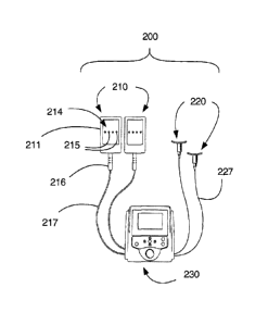
Another exemplary laser applicator system according to the present invention
is
illustrated in Figs. 9 and 10 and generally comprises at least one first laser
applicator 210
provided with a plurality of low-power laser diodes, at least one second laser
applicator
220 provided with at least one laser diode, and a laser control device 230
configured for
controllably communicating and cooperating with the first and second laser
applicators
210, 220. The first laser applicator generally comprises a housing 211
configured to
contain and retain a contact plate 214 fitted and cooperating with a plurality
of laser
diodes 215. The contact plate 214 is configured to contact a portion of a
subject's body
surface. Suitable laser diodes are exemplified by multi-channel AIGaLnP laser
diodes
configured for continuous and modulated continuous power outputs in the range
of about
10 mW to about 100 mW of light waves in the range of about 630 nm to about 680
nm
with a modulation frequency of 0 to about 10 Hz. It is suitable for the first
laser
applicator 210 to be hardwired-connected to the laser control device 230.
Alternatively,
the first laser applicator 210 may be provided with a female electrical
receptacle (not
shown) configured for releasably engaging male plug lead 216 connected to the
laser
control device 230 by a suitable gauge wire 217. The second laser applicator
220 is
configured to cooperate and communicate with one suitable laser diode 225. A
suitable
laser diode for the second laser applicator 220 is exemplified by a multi-
channel
AlGaLnP laser diode configured for continuous and modulated continuous power
outputs
in the range of about 0 mW to about 50 mW of light waves in the range of about
630 nm
to about 680 nm with a modulation frequency of 0 to about 10 Hz. As
exemplified in Fig.
10, the second laser applicator 220 comprises a housing 221 having a generally
elongate
concave surface 222 configured for contacting a subject's body surface with a
laser diode
receptacle 223 extending away from the concave surface 222 of the housing 221.
An
aperture 224 communicating with the laser diode receptacle 223 is provided
about center
of the concave surface 222 for transmitting laser light therethrough. A
suitable laser diode
215for the second laser applicator 220 is exemplified by a multi-channel
AlGaLnP laser
DM VAN/253729-16266/6739700.1
CA 02604112 2007-09-24
-21 -
diode configured for continuous and modulated continuous power outputs in the
range of
about 0 mW to about 50 mW of light waves in the range of about 630 nm to about
680
nm with a modulation frequency of 0 to about 10 Hz. It is suitable for the
second laser
applicator 220 to be connected to the laser control device 230 with a suitable
gauge wire
227. The laser control device 230 comprises a graphical user interface (GUI),
a visual
display unit 231, suitable user input electronic devices configured for
communicating and
cooperating with power modulation hardware, and suitably configured software.
Although reference is made herein to interconnecting the exemplary laser
applicators 210
and 220 with the exemplary laser control device with wires 217, 227, it is
within the
scope of the present invention to configure the laser applicators 210, 220 and
the laser
control device 230 with provide wireless transmission/reception devices for
cooperatively
controllably generating laser light waves and energy for application of
lipolysis
treatments to a subject's body surface.
Exemplary methods for the use of the laser applicators in cooperation with the
laser control devices of the lipolysis systems of the present invention are
illustrated in
Figs 11-15. For example, a suitable method for liquefaction of subcutaneous
fats about a
subject's waistline and for concurrent removal of the liquefied fats from that
area of the
of the subject's body is illustrated in Fig. 11. As shown in Fig 11(a), at
least two first laser
applicators 210 are first positioned next to each other on the right side of
the subject's
body about the right lateral waistline and secured in place with a suitable
device (not
shown) as exemplified by adhesive strips, elastic band, adjustable belt,
adjustable strap
and the like. At least one second laser applicator 220 is positioned
approximate the upper
inguinal joint area defining the connection of each upper thigh with the body
torso after
which both laser applicators 220 are secured in place with a suitable device
as
exemplified by adhesive strips, elastic bands and the like. The laser control
device (not
shown in Fig. 11) is then manipulated to provide about 10 to about 30 minutes
of a first
laser irradiation to the body surfaces contacting the laser applicators 210,
220 and the
underlying subcutaneous regions for liquefaction of fats in adipose cells
therein. At the
conclusion of the first laser irradiation period, the at least two first laser
applicators are
moved to a second position about the medial waistline in the middle of the
subject's torso
shown as 210' in Fig. 11(b) and then secured in place. Each second laser
applicator is
DM VAN/253729-16266/6739700.1
CA 02604112 2007-09-24
-22-
moved downward along the inguinal joint area defining the connection of each
upper
thigh with the body torso to about the mid-point of the joint area shown as
220' in Fig.
11(b) and then is secured in place. The laser control device is then
manipulated to provide
about 10 to about 30 minutes of a second laser irradiation to the body
surfaces contacting
the laser applicators in the 210'and 220' positions and the underlying
subcutaneous
regions for liquefaction of fats in adipose cells therein. At the conclusion
of the second
laser irradiation period at least two first laser applicators are moved to a
third position
about the left lateral waistline of the subject's torso as shown as 210" in
Fig. 11(c) and
then secured in place. Each second laser applicator is moved downward along
the
inguinal joint area defining the connection of each upper thigh with the body
torso to
about the lower end of the inguinal joint area shown as 220" in Fig. 11(c) and
then is
secured in place. The laser control device is then manipulated to provide
about 10 to
about 30 minutes of a third laser irradiation to the body surfaces contacting
the laser
applicators in the 210"and 220" positions and the underlying subcutaneous
regions for
liquefaction of fats in adipose cells therein. At the conclusion of the third
laser irradiation
period the first and second laser applicators are removed and if so desired,
employed for
further lipolysis treatments elsewhere on the subject's body surface. It is to
be noted that
laser irradiation provided by the second laser applicators 220 positioned
about the
inguinal joint areas will stimulate the lymph glands and associated lymph
vessels located
in the subcutaneous areas of the inguinal joint areas and thus facilitate
movement of
liquefied fat from the subcutaneous regions underlying the portions of the
body surface
receiving laser irradiation from the first laser applicators 210, will
facilitate its movement
to the lymph glands and its subsequent removal from those areas by the
lymphatic
system.
Figs. 12(a)-12(c) are schematic illustrations of exemplary positioning of the
laser
applicators about a subject's body torso for liquefaction of fats about their
abdominal
oblique muscle areas. As shown in Fig 12(a), at least two first laser
applicators 210 are
first positioned next to each other about the upper lateral oblique area of
the subject's
body torso and secured in place with a suitable device (not shown) as
exemplified by
adhesive strips, elastic band, adjustable belt, adjustable strap and the like.
At least one
second laser applicator 220 is positioned approximate the upper inguinal joint
area
DM VAN/253729-16266/6739700.1
CA 02604112 2007-09-24
-23-
defining the connection of each upper thigh with the body torso after which
both laser
applicators 220 are secured in place with a suitable device as exemplified by
adhesive
strips, elastic bands and the like. The laser control device (not shown in
Fig. 12) is then
manipulated to provide about 10 to about 30 minutes of a first laser
irradiation to the
body surfaces contacting the laser applicators 210, 220 and the underlying
subcutaneous
regions for liquefaction of fats in adipose cells therein. At the conclusion
of the first laser
irradiation period, the at least two first laser applicators are moved to a
second position
about the middle oblique area of the subject's body torso shown as 210' in
Fig. 12(b) and
then secured in place. Each second laser applicator is moved downward along
the
inguinal joint area defining the connection of each upper thigh with the body
torso to
about the mid-point of the joint area shown as 220' in Fig. 12(b) and then is
secured in
place. The laser control device is then manipulated to provide about 10 to
about 30
minutes of a second laser irradiation to the body surfaces contacting the
laser applicators
in the 210'and 220' positions and the underlying subcutaneous regions for
liquefaction of
fats in adipose cells therein. At the conclusion of the second laser
irradiation period at
least two first laser applicators are moved to a third position about the
lower oblique area
of the subject's torso as shown as 210" in Fig. 12(c) and then secured in
place. Each
second laser applicator is moved downward along the inguinal joint area
defining the
connection of each upper thigh with the body torso to about the lower end of
the inguinal
joint area shown as 220" in Fig. 12(c) and then is secured in place. The laser
control
device is then manipulated to provide about 10 to about 30 minutes of a third
laser
irradiation to the body surfaces contacting the laser applicators in the
210"and 220"
positions and the underlying subcutaneous regions for liquefaction of fats in
adipose cells
therein. At the conclusion of the third laser irradiation period the first and
second laser
applicators are removed and if so desired, employed for further lipolysis
treatments
elsewhere on the subject's body surface. It is to be noted that laser
irradiation provided by
the second laser applicators 220 positioned about the inguinal joint areas
will stimulate
the lymph glands and associated lymph vessels located in the subcutaneous
areas of the
inguinal joint areas and thus facilitate movement of liquefied fat from the
subcutaneous
regions underlying the portions of the body surface receiving laser
irradiation from the
first laser applicators 210, will facilitate its movement to the lymph glands
and its
DM VAN/253729-]6266/6739700.1
CA 02604112 2007-09-24
-24-
subsequent removal from those areas by the lymphatic system.
Figs. 13(a)-13(c) are schematic illustrations of exemplary positioning of the
laser
applicators about a subject's body torso for liquefaction of fats about their
upper
abdominal areas. As shown in Fig 13(a), at least two first laser applicators
210 are first
positioned next to each other about the upper abdomen area on the right side
of the
subject's body and secured in place with a suitable device (not shown) as
exemplified by
adhesive strips, elastic band, adjustable belt, adjustable strap and the like.
At least one
second laser applicator 220 is positioned approximate the upper inguinal joint
area
defining the connection of each upper thigh with the body torso after which
both laser
applicators 220 are secured in place with a suitable device as exemplified by
adhesive
strips, elastic bands and the like. The laser control device (not shown in
Fig. 13) is then
manipulated to provide about 10 to about 30 minutes of a first laser
irradiation to the
body surfaces contacting the laser applicators 210, 220 and the underlying
subcutaneous
regions for liquefaction of fats in adipose cells therein. At the conclusion
of the first laser
irradiation period, the at least two first laser applicators are moved to a
second position
about the middle upper abdomen area of the subject's body torso shown as 210'
in Fig.
13(b) and then secured in place. Each second laser applicator is moved
downward along
the inguinal joint area defining the connection of each upper thigh with the
body torso to
about the mid-point of the joint area shown as 220' in Fig. 13(b) and then is
secured in
place. The laser control device is then manipulated to provide about 10 to
about 30
minutes of a second laser irradiation to the body surfaces contacting the
laser applicators
in the 210'and 220' positions and the underlying subcutaneous regions for
liquefaction of
fats in adipose cells therein. At the conclusion of the second laser
irradiation period at
least two first laser applicators are moved to a third position about the
upper abdomen
area on the right side of the subject's body as shown as 210" in Fig. 13(c)
and then
secured in place. Each second laser applicator is moved downward along the
inguinal
joint area defining the connection of each upper thigh with the body torso to
about the
lower end of the inguinal joint area shown as 220" in Fig. 13(c) and then is
secured in
place. The laser control device is then manipulated to provide about 10 to
about 30
minutes of a third laser irradiation to the body surfaces contacting the laser
applicators in
the 210"and 220" positions and the underlying subcutaneous regions for
liquefaction of
DM VAN/253729-16266/6739700.1
CA 02604112 2007-09-24
-25-
fats in adipose cells therein. At the conclusion of the third laser
irradiation period the first
and second laser applicators are removed and if so desired, employed for
further lipolysis
treatments elsewhere on the subject's body surface.
Figs. 14(a)-14(d) are schematic illustrations of exemplary positioning of the
laser
applicators about a subject's body torso for liquefaction of fats about their
upper thigh
areas. As shown in Fig 14(a), one first laser applicator 210 is positioned on
the subject's
right upper thigh adjacent a vertical linear axis extending upward from the
right knee
while a second first applicator 210 is positioned on the subject's left upper
thigh adjacent
a vertical linear axis extending upward from the left knee. Both first laser
applicators are
secured in place with a suitable device (not shown) as exemplified by adhesive
strips,
elastic band, adjustable belt, adjustable strap and the like. At least one
second laser
applicator 220 is positioned approximate the mid-portion area of the inguinal
joint area
defining the connection of each upper thigh with the body torso as shown in
Fig 14(d)
after which both laser applicators 220 are secured in place with a suitable
device as
exemplified by adhesive strips, elastic bands and the like. The laser control
device (not
shown in Fig. 14) is then manipulated to provide about 10 to about 30 minutes
of a first
laser irradiation to the body surfaces contacting the laser applicators 210,
220 and the
underlying subcutaneous regions for liquefaction of fats in adipose cells
therein. At the
conclusion of the first laser irradiation period, the first laser applicator
210 is re-
positioned on the subject's right upper thigh to a position facing the left
upper thigh while
the second first applicator 210 is re-positioned on the subject's left upper
thigh adjacent
to a position facing the right upper thigh as shown in Fig. 14(b), and both
are secured in
place. The two second laser applicators are maintained in the same position
shown in Fig.
14(d). The laser control device is then manipulated to provide about 10 to
about 30
minutes of a second laser irradiation to the body surfaces contacting the
laser applicators
in the 210'and 220' positions and the underlying subcutaneous regions for
liquefaction of
fats in adipose cells therein. At the conclusion of the second laser
irradiation period, the
first laser applicator 210 is re-positioned on the subject's right upper thigh
to a backward-
facing position while the second first applicator 210 is re-positioned on the
subject's left
upper thigh to a similar backward-facing position as shown in Fig. 14(c), and
both are
secured in place. The two second laser applicators are maintained in the same
position
DM VAN/253729-16266/6739700.1
CA 02604112 2007-09-24
-26-
shown in Fig. 14(d). The laser control device is then manipulated to provide
about 10 to
about 30 minutes of a third laser irradiation to the body surfaces contacting
the laser
applicators in the 210"and 220" positions and the underlying subcutaneous
regions for
liquefaction of fats in adipose cells therein. At the conclusion of the third
laser irradiation
period the first and second laser applicators are removed and if so desired,
employed for
further lipolysis treatments elsewhere on the subject's body surface.
Figs. 15(a)-15(d) are schematic illustrations of exemplary positioning of the
laser
applicators about a subject's body torso for liquefaction of fats about their
lower back
areas. As shown in Fig 15(a), at least two first laser applicators 210 are
first positioned
next to each other on the left side of the subject's body about the hip area
and secured in
place with a suitable device (not shown) as exemplified by adhesive strips,
elastic band,
adjustable belt, adjustable strap and the like. At least one second laser
applicator 220 is
positioned approximate the upper inguinal joint area defining the connection
of each
upper thigh with the body torso as shown in Fig. 15(d) after which both laser
applicators
220 are secured in place with a suitable device as exemplified by adhesive
strips, elastic
bands and the like. The laser control device (not shown in Fig. 15) is then
manipulated to
provide about 10 to about 30 minutes of a first laser irradiation to the body
surfaces
contacting the laser applicators 210, 220 and the underlying subcutaneous
regions for
liquefaction of fats in adipose cells therein. At the conclusion of the first
laser irradiation
period, the at least two first laser applicators are moved to a second
position about the
above the hip area in the middle of the subject's torso shown as 210' in Fig.
15(b) and
then secured in place. Each second laser applicator is moved downward along
the
inguinal joint area defining the connection of each upper thigh with the body
torso to
about the mid-point of the joint area shown as 220' in Fig. 15(d) and then is
secured in
place. The laser control device is then manipulated to provide about 10 to
about 30
minutes of a second laser irradiation to the body surfaces contacting the
laser applicators
in the 210'and 220' positions and the underlying subcutaneous regions for
liquefaction of
fats in adipose cells therein. At the conclusion of the second laser
irradiation period at
least two first laser applicators are moved to a third position about on the
right side of the
subject's body about the hip area as shown as 210" in Fig. 15(c) and then
secured in
place. Each second laser applicator is moved downward along the inguinal joint
area
DM VANl253729-16266l6739700.1
CA 02604112 2007-09-24
-27-
defining the connection of each upper thigh with the body torso to about the
lower end of
the inguinal joint area shown as 220" in Fig. 15(d) and then is secured in
place. The laser
control device is then manipulated to provide about 10 to about 30 minutes of
a third
laser irradiation to the body surfaces contacting the laser applicators in the
210"and 220"
positions and the underlying subcutaneous regions for liquefaction of fats in
adipose cells
therein. At the conclusion of the third laser irradiation period the first and
second laser
applicators are removed and if so desired, employed for further lipolysis
treatments
elsewhere on the subject's body surface.
Those skilled in these arts will understand that the exemplary methods shown
in
Figs. 11-15 for the use of lipolysis systems to apply lipolysis treatments to
a subject's
body surface may be suitably modified to personalize the methods to individual
subjects.
For example, the lipolysis treatments about a certain body portion e.g., such
as the waist
area and the lower back area, may be applied in the reverse order to that
described. Also,
the exemplary methods are applicable to all areas about a subject's body torso
and their
extremities. Also, a suitable duration of laser irradiation applied to each
body portion may
be selected based on a target amount of fat liquefaction desired for each
target body
portion. Furthermore, those skilled in these arts will understand that the
laser applicators,
the lipolysis systems and the methods for their use according to the present
invention may
be employed for body sculpting, contouring and toning by: (a) selection of the
numbers
of first and second laser applicators used for each lipolysis treatment, and
(b) by selecting
specific combinations of body torso and extremity target surface areas for
each lipolysis
treatment. For clarity, lipolysis treatment in this context means a
combination of three
time-selected laser irradiations applied to one or more body surface areas
during one
lipolysis treatment session. For example, an exemplary sixty-minute lypolysis
treatment
session may comprise three ten-minute laser irradiations about a subject's
waistline area
followed by three ten-minute laser irradiations about their upper abdomen
area, or
alternatively, by three ten minute laser irradiations about their lower back
area. An
exemplary 120-minute lipolysis treatment session may comprise two sets of
three ten-
minute laser irradiations about a subject's body torso followed by a set of
three ten-
minute laser irradiations about their upper thigh areas and a set of ten-
minute irradiations
about their upper arms.
DM VAN/253729-16266/6739700.1
CA 02604112 2007-09-24
-28-
It is within the scope of the present invention to combine the laser
applicators,
lipolysis systems comprising the laser applicators, and the methods for their
use as
exemplified herein, with other suitable devices and apparatus configured for a
subject's
use for physical exercising. Such suitable physical exercising devices and
apparatus
include equipment commonly referred to as "whole body vibration" devices that
are
provided with an exercise platform or surface, configured to provide
controllable
vibrations to a subject positioned thereon. Suitable whole body vibration
devices are
exemplified by the Soloflex WBV vibrating exercise platform (Soloflex and
Soloflex
WBV are registered trademarks of Soloflex Inc., Hillsboro, OR, USA), the
Nobelrex Kl
machines (Nobelrex K-1 Ltd., OR, USA), the Power Plate pro5 machines (Power
Plate
is a registered trademark of Power Plate North America Ltd., Northbrook IL.
USA), the
VibePlate platforms (VibePlate is a registered trademark of VibePlate Inc.,
Lincoln NE,
USA) and the like. An exemplary method for combining the use of the laser
applicators
and lipolysis systems comprising the laser applicators of the present
invention comprises
securing to a target portion of a subject's body surface, at least one laser
applicator
configured as described herein and cooperatively communicating with a suitable
laser
control devise as provided with a lipolysis system of the present invention,
after which
the subject mounts a whole body vibration device in a suitable position. The
laser
irradiation treatment is then provided for a selected period of time
concurrent with the
delivery of vibrations to the subject by the whole body vibration device. At
the
conclusion of the laser irradiation treatment, the subject demounts from the
whole body
vibration device for re-positioning of the at least one applicator, after
which, the subject
remounts the whole body vibration machine for an addition period of concurrent
delivery
of laser irradiation from the laser applicator and vibrations from the whole
body vibration
device. The subject may selectively receive: (a) concurrent laser irradiation
and whole
body vibrations, or (b) laser irradiation only, or (c) whole body vibrations
only during the
course of a lipolysis treatment session with the lipolysis system of the
present invention.
Those skilled in these arts will understand that combining whole body
vibration
treatments from whole body vibration devices concurrent with lipolysis
treatments by the
lipolysis systems of the present invention will facilitate and enhance
movement of
liquefied fats from within adipose cells into the interstitial spaces, and
from the interstitial
DM VAN/253729-16266/6739700.1
CA 02604112 2007-09-24
-29-
spaces into the groin area where they are absorbed into the lymphatic system
which will
then transport the liquefied fats away from the groin area for further
processing and
elimination by the subject's normal physiological processes.
It is within the scope of the present invention to combine the laser
applicators,
lipolysis systems comprising the laser applicators, and the methods for their
use as
exemplified herein, with other types of non-surgical cosmetic treatments
commonly
employed for dissolving fats and cellulose and referred to by those skilled in
these arts as
mesotherapy and lipodissolve treatments. Mesotherapy typically involves
multiple
injections of pharmaceutical compositions and/or homeopathic compositions, and
or plant
extracts and/or vitamins into subcutaneous regions of a subject's body having
protuberances caused by fat accumulations, while lipodissolve treatments
typically
involve multiple injections of phosphatidylcholine deoxycholate (PCDC) into
the same
target areas that mesotherapy is delivered. Mesotherapy and lipodissolve
treatments are
purported to cause lysis of adipose cells that are then removed from the body
via its
normal physiological functioning. Those skilled in these arts will understand
that
mesotherapy and lipodissolve treatments can be provided in combination with
lipolysis
treatments with the laser applicators and lipolysis systems of the present
invention. For
example, a series of PCDC injections can be subcutaneously administered to
targeted
portions of a subject's body surface. At least one or alternatively, a
plurality of laser
applicator according to the present invention can then be secured to an
injection site for
application of laser irradiation thereto with the lipolysis system of the
present invention.
It is suitable to secure a first laser applicator comprising a plurality of
laser diodes, to an
injection site and to concurrently secure a second laser applicator comprising
a single
laser diode, to a site about the inguinal joint area.
The examples presented below are included as embodiments of the present
invention, but are not intended to limit the scope of the present invention.
The example presented below is included as an exemplary embodiment of the
present invention, but is not intended to limit the scope of the present
invention.
DM VAN/253729-16266/6739700.1
CA 02604112 2007-09-24
-30-
EXAMPLE 1
Methods:
(a) Clinical trial:
Forty healthy men and women between the ages of 18-65 years of age inclusive
with a body mass index (BMI) no greater than 29.9 kg/mZ were randomized in a
1:1 ratio
to an experimental laser treatment or to a control laser treatment.
Randomization was
created from random number tables and the treatment codes were stored in
sealed
envelopes during the study. Subjects could not be using light sensitizing
agents,
undergoing photodynamic therapy or using diuretics. Subjects were required to
have a
stable weight, gaining or losing no more than 2.5 kg in the 6 months prior to
the trial.
Subjects could not be on a weight reduction regimen, and they were asked not
to change
their diet or exercise habits during the trial.
An exemplary lipolysis system of the present invention similar to the system
illustrated in Fig. 9 was employed for the clinical trial and comprised two
laser
applicators each provided with four low-power laser diodes (multi-channel
AlGaLnP
laser diodes configured for continuous and modulated continuous power outputs
in the
range of about 130 mW to about 170 mW of light waves in the range of about 630
nm to
about 680 nm with a modulation frequency of 0 to about 10 Hz), and a laser
control
device configured for controllably communicating and cooperating with the two
laser
applicators. Each subject received two treatments per week for a total of
eight treatments
over four weeks. Each treatment session lasted approximately thirty minutes.
The two
laser applicators were placed over the waist bilaterally in three positions
and the laser was
activated for ten minutes in each of these positions to encompass the waist
from the back
to the front. Two operators conducted each treatment session throughout the
study. One
operator administered the treatment, and the other operator, who was blinded
to treatment
allocations, obtained measurements and photographs. The operator administering
the
treatment remained blinded to photographic and girth measurements. Each
subject was
advised about the rules of blinding, and individual taking photographs and
measurements
could not relay this information to the subject. The operator administering
the treatment
DM VAN/253729-16266/6739700.1
CA 02604112 2007-09-24
-31-
did not enter the room where the photographs and measurements were obtained. A
new
Case Report Form was used for each measurement session and these forms were
placed
in a sealed envelope until data was analyzed at the end of the study. A
separate person
who was not involved in other aspects of the study did the blinded evaluations
of the
photographs.
All subjects had photographs taken at a standardized distance with standard
background and lighting. Girth measurements of the waist were obtained in the
manner
recommended by the United States National Institutes of Health National
Institute for
Health guidance (NIH) at the iliac crest using a tape measure with
standardized tension
and parallel to the floor following the protocol outlined in the journal
Obesity Research,
1998, Sep;6 Suppl. 2: 51S-209S(no authors listed). A reference point on the
body for the
pictures and measurements was relocated at each evaluation by measuring a
distance
from the floor that was determined in the first measurement at baseline. The
specified
measured distance was used to ensure all measurements and photographs are
obtained in
the same location. The camera was placed on a tripod at a fixed distance from
the floor,
but was adjusted to a specific height of each individual participant.
Standardized waist
measurements were taken at baseline, treatment session #3 and treatment
session #8.
Standardized photographs were taken before an after the initial treatment, t
treatment
session #3 and treatment session #8. Weight was measured and BMI calculated at
baseline and at treatment session #8 (week 4). Blood pressure was measured at
baseline,
treatment session #3 and treatment session #8. Any adverse events were noted
in the
case report forms.
(b) In vitro study using human fat cells
Human fat cells were prepared in two 12-well plates. Three of the cells in the
plates were left as a control. Fresh plasma replaced one third of the cell
culture media in
another three wells. The next three wells had one third of the media replaced
with fresh
human white cells in suspension. The final three wells in each plate had one
third of the
media replaced by a combination of fresh human plasma and white blood cells.
One of
the plated was irradiated for ten minutes with a laser applicator comprising 4
laser diodes
(multi-channel AlGaLnP laser diodes configured for continuous and modulated
DM VAN/253729-16266/6739700.1
CA 02604112 2007-09-24
-32-
continuous power outputs in the range of about 130 mW to about 170 mW of light
waves
in the range of about 630 nm to about 680 nm with a modulation frequency of 0
to about
Hz), and the other was left as a non-irradiated control. The conditioned media
from
the four types of wells from each plate were tested for membrane attack
complexes of
5 complement (MAC) using an ELISA assay.
Results:
(a) Clinical Trial
The groups were well balanced at baseline, and the group characteristics are
illustrated in Table 1. Weight and BMI did not change significantly over the 8
treatments
10 and 4 weeks. Blood pressure did not change significantly from baseline to
treatment 3,
from treatment 3 to treatment 8 or from baseline to treatment 8. Each
treatment with the
LipoLaser gave an approximate loss of 0.4 cm to 0.5 cm in waist girth. This
difference,
0.405 cm (Laser -0.59 + 0.708 cm vs. Placebo -0.19 0.47 cm (mean + SD), was
significant (p<0.05) on the third treatment session done during week two on
the
completers analysis, but was not statistically significant by the intent to
treat analysis.
The cumulative girth loss at treatment session #3 on week two was a
significant 1.74 cm
(Laser -1.895 + 2.967 cm vs. Placebo -0.16 + 2.458 cm) (p<0.05) on both the
completers
analysis and by intent to treat analysis. Cumulative girth loss at treatment
session #8 (4
weeks of treatment) was 2.15 cm (Laser -0.781 2.817 cm vs. Placebo 1.353 +
2.644
cm) in those who maintained their weight within 1.5 kg of their baseline
weight (p<0.05).
The standardized pictures of the participants showed a significant 1.21
difference (Laser
1.21 + 0.419 vs. Placebo 0+ 0 cm) in appearance on a 0-3 scale favoring the
LipoLaser
group comparing the baseline to the week 4 (treatment 8) pictures (p<0.001).
When only
those participants that remained within 1.5 kg of their baseline weight were
considered,
the improvement in appearance increased to 1.25 (Laser 1.25 + 0.447 vs.
Placebo 0+ 0)
on a 0-3 scale comparing the baseline to the week 4 (treatment session #8)
pictures
(p<0.001). Girth losses in the laser and placebo groups at the various time
points are
illustrated in Fig. 16. The girth difference in the Laser group compared to
the placebo
group is illustrated in Fig. 17. The differences in appearance from baseline
to week 4
DM VAN/253729-16266/6739700.1
CA 02604112 2007-09-24
-33-
(treatment session #8) in the whole group and the subjects who remained within
1.5 kg of
their baseline weight are illustrated in Fig.18. (One subject withdrew from
the study due
to scheduling conflicts. The individual was in the treatment group, and lost
0.2 cm in
waist girth with the initial treatment prior to withdrawing).
Table 1: Clinical trial participant data.
Variable Lipolysis Group Placebo Group P-Value
Number enrolled 20 20
Gender 0.0765
Female 19 15
Male 1 5
Age (Years) 35.1 38.35 0.3292
SD 9.11 11.55
Weight (kg) 63.97 67.31 0.3705
SD 8.23 14.31
Height (cm) 164.12 165.68 0.5341
SD 5.99 9.32
Body Mass Index (kg/m2) 23.77 24.35 0.4641
SD 2.02 2.87
SBP 120.15 121.40 0.7330
SD 11.98 11.00
DBP 75.35 75.00 0.8922
SD 8.23 8.00
Values are means and standard deviation (SD)
(b) In vitro study using human fat cells
The human fat cells in the non-laser treated 12-well plate remained intact.
The
human fat cells in culture media treated with the laser remained intact, as
did the human
fat cells treated with the laser in the presence of fresh human white blood
cells. The fat
cells treated in the presence of fresh human serum or fresh human serum
combined with
DM VAN/2 53 7 29-1 6266/67 3 9700.1
CA 02604112 2007-09-24
-34-
fresh human white blood cells released their fat. The MAC was present in both
of the
conditions in which the wells were treated with the laser in the presence of
human serum
or human serum with white blood cells.
Discussion:
A single lipolysis treatment session provided by an exemplary lipolysis system
of
the present invention was effective in providing giving girth loss, and
repeated treatment
sessions further provided between 0.4 to 0.5 cm girth loss per treatment
session. This
difference was statistically significant at treatment session #3 demonstrating
that the
effect of the lipolysis system of the present invention does not appear to
diminish with
repeated treatments through time. The 1.74 cm girth loss at treatment session
#3 suggests
that the methods of use of the lipolysis systems as described herein are
cumulative in
their effect on girth loss.
It is obvious that weight change over the course of treatment would change
waist
circumference and confound the results. The subjects selected for the study
were asked
not to lose or gain weight over the course of the study. Since some subjects
did gain or
lose a significant amount of weight over the 4 week study, the cumulative fat
loss was
analyzed only on those subjects whose weight was within 1.5 kg of their
baseline weight.
The selection of a 1.5 kg limit for weight fluctuation was based on the fact
that this study
was the length of a 4-week menstrual cycle minimizing the effect of
menstrually-related
fluid shifts in women (Robinson et al., 1965, Brit. J. Nutr. 19: 225-235).
Girth loss over the course of the study was greater than 2 cm and
statistically
significant. The subjects in this study were not obese and an approximate 1
inch (2.54
cm) reduction in waist girth over the course of 8 treatment sessions over a 4-
week period
was clinically significant. The blinded ratings of the baseline pictures
compared to the
treatment session #8 (week 4) pictures taken in a standardized way
demonstrated an
improvement in appearance that was highly statistically significant. As
expected, the
improvement was greater when limiting the comparison to only those subjects
that
remained within 1.5 kg of their baseline weight.
DM VAN/253729-16266/6739700.1
CA 02604112 2007-09-24
-35-
Thus, the laser applicators, lipolysis systems comprising the laser
applicators, and
methods for their use provide significant waist girth loss that is sustained
over repeated
treatments and is cumulative over 4 weeks of 8 treatments. This waist girth
loss was
almost one inch (2.54 cm) in magnitude. Therefore, the exemplary embodiments
of the
present invention disclosed herein provided both a clinically and
statistically significant
improvement in appearance.
While the exemplary laser applicators and lipolysis systems of the present
invention have been described with low power laser diodes configured to
produce power
outputs in the range comprising about 10mW to about 100mW with light waves in
the
range of 635nm to 680 nm, it is also within the scope of the present invention
to provide
laser applicators and laser applicator systems configured with combinations of
low power
laser diodes and medium power laser diodes having power outputs in the range
of about
80mW to about 160mW with light waves in the range of 780nm to 980 nm.
Although the present invention has been described with reference to certain
exemplary embodiments thereof, in view of numerous changes and variations that
will be
apparent to persons skilled in the art, the scope of the present invention is
to be
considered limited solely by the appended claims.
DM VAN/253729-16266/6739700.1