Note: Descriptions are shown in the official language in which they were submitted.
CA 02604176 2007-10-10
1
WO 2006/124469 PCT/US2006/018118
GLAND LEAKAGE SEAL SYSTEM
CROSS-REFERENCE TO RELATED APPLICATIONS
[001] This application claims priority to United States Utility Patent
Application No. 11/382,606 filed on May 10, 2006 entitled, GLAND LEAKAGE
SEAL SYSTEM. This application also claims benefits from United States
Provisional Patent Application, Serial no. 60/680,870 filed on May 12, 2005
entitled, GLAND LEAKAGE VACUUM SYSTEM, the contents of which are
hereby incorporated by reference.
BACKGROUND OF THE INVENTION
1. The Field of the Invention
[002] The present invention relates to a seal system for use in a closed loop
thermodynamic system. In more particular, the present invention relates to a
seal
system for capturing working fluid that has leaked or escaped from an
expansion
turbine and returning the escaped working fluid to a mixed working fluid
thermodynamic cycle, such as a Kalina Cycle.
2. The Relevant Technology
[003] Thermal energy can be usefully converted into mechanical and then
electrical form. Methods of converting the thermal energy of low and high
temperature heat sources into electric power represent an important area of
energy
generation. There is a need for increasing the efficiency of the conversion of
such
low temperature heat to electric power.
[004] Thermal energy from a heat source can be transformed into mechanical
and then electrical form using a working fluid that is expanded and
regenerated in a
closed system operating on a thermodynamic cycle. The working fluid can
include
components of different boiling temperatures, and the composition of the
working
CA 02604176 2007-10-10
2
WO 2006/124469 PCT/US2006/018118
fluid can be modified at different places within the system to improve the
efficiency
of energy conversion operation.
[005] Typically multi-component working fluids include a low boiling point
component and a higher boiling point component. By utilizing the combination
of
the low boiling point component and a higher boiling point component, an
external
heat source stream, such as industrial waste heat, can be more efficiently
utilized for
electricity production. Examples of a low boiling point component include
water.
[006] Once the working fluid has been heated, it is expanded at a turbine to
convert the potential energy to mechanical energy which is utilized in the
generation
of electricity. One difficulty experienced at typical turbines is that working
fluid can
leak and escape to the ambient. This problem is exacerbated when one or more
components of the working fluid are in a vapor or super heated vapor form.
Leakage of working fluid can reduce the total volume of working fluid being
utilized
in a cycle. This can create additional complications where the working fluid
is being
utilized in a closed loop. Additionally, at times one component of a multi-
component working fluid can leak in disproportionate amounts relative to the
other
components. As a result, the species balance of the multi-component working
fluid
can be interrupted. Where ammonia is utilized as one of the components of the
working fluid, the release of ammonia to the atmosphere can be undesirable due
to
the material properties of ammonia. As a result, controlling release of either
component can be highly desirable.
[007] Turbine seal systems have been created to moderate fluid leakage
problems. However, such seal systems typically require modification or
wholesale
changes to the turbine system to be effective. As a result, specialized
turbines must
be created based on the particular requirements of the heat source stream
being
utilized. This can render the turbines prohibitively expensive and/or
interfere with
CA 02604176 2007-10-10
3
WO 2006/124469 PCT/US2006/018118
desired operation of the turbine engineering. Additionally, some systems
require
vacuum or other pressures in the systems to be maintained at particular
parameters.
As a result of the overall system requirements can become more expensive than
desired.
BRIEF SUMMARY OF THE INVENTION
[008] The present invention is directed to a gland leakage or turbine seal
system. The turbine seal system is configured to capture working fluid which
is
escaping from a thermodynamic system having a multi-component working fluid,
such as a Kalina Cycle system, condense the captured working fluid, and return
the
condensate back to the multi-component working fluid thermodynamic system. The
turbine seal system is configured to apply nitrogen or other non-condensable
gas, or
other material, to capture or mix with the escaping working fluid. The
combined
mixture of the escaped working fluid and the nitrogen utilized to capture the
working fluid is evacuated by an exhaust or compressor which maintains a
desired
vacuum in a turbine gland compartment. The combined mixture can then be sent
to
a condenser to condense the working fluid vapor and evacuate the non-
condensables. Once the non-condensables have been evacuated, the working
stream
is pumped to a higher pressure, and prepared to be introduced back into the
thermodynamic system.
[009] According to one embodiment of the present invention, once the
combined mixture has been condensed and the resulting working stream pumped to
a higher pressure, the working stream is preheated and partially boiled. The
working
stream is then separated by a separator, wherein the vapor of the working
stream (i.e.
rich stream) is returned to the thermodynamic system and the liquid portion
(i.e. lean
stream) of the working stream is combined with the combined mixture.
CA 02604176 2007-10-10
4
WO 2006/124469 PCT/US2006/018118
[010] According to another embodiment of the present invention, a mechanical
compressor is utilized to pressurize the combined mixture to a level that it
can be
fully condensed and distilled at given coolant temperatures. Utilizing a
compressor
enables condensation of the combined mixture at available coolant
temperatures.
Additionally, this allows the system to maintain the desired seal vacuum even
under
extraordinarily hot ambient conditions. Optionally, a heat exchanger can be
utilized
to manipulate the parameters of the combined mixture to approximate the
combined
mixture's dew point in order to decrease the mechanical power required for pre-
condensation compression.
[011] The mechanical compressor allows for desired system operation under a
wide variety of ambient temperature conditions. According to one embodiment,
the
mechanical compressor may be required only a portion of the time and may
otherwise be bypassed. Optionally, the compressor may be utilized even when
not
required for condensation to pressurize the condenser above ambient pressure
such
that non-condensables may be vented without an additional blower.
[012] According to another embodiment of the present invention, a two-stage,
heat-operated distillation system is utilized. By utilizing a two-stage, heat-
operated
distillation system, pressurized vapor, which has already been through the
condenser
and which has a temperature higher than the dew point curve, can be distilled
to
produce a sufficient liquidity for dilution. In the illustrated embodiment,
once the
working stream has been pumped to a higher pressure, it is preheated and
partially
boiled and sent to a first separator. At the first separator, the working
stream having
a temperature that is higher than the dew point (i.e. rich stream) can be sent
to a
vapor cooler. At the vapor cooler, the parameters of the rich stream can be
changed
to approximate the rich stream's dew point, and then the rich stream can be
separated at a second dew point separator. At the dew point separator, rich
stream
CA 02604176 2007-10-10
WO 2006/124469 PCT/US2006/018118
can be returned to the multi-component thermodynamic system having
substantially
the same parameters as the expanded working fluid exiting the turbines in the
thermodynamic system.
[013] After the combined mixture has been condensed, the flow of the working
stream through the pump can be adjusted to maintain desired system operation.
For
example, the flow of working stream can be utilized to adjust the vacuum in
the
turbine seal and the overall flow of fluid through the turbine seal system.
Additionally, flow of a heat source stream through the heat exchangers can be
throttled to fiuther alter the turbine seal system parameters.
[014] These and other objects and features of the present invention will
become
more fully apparent from the following description and appended claims, or may
be
learned by the practice of the invention as set forth hereinafter.
BRIEF DESCRIPTION OF THE DRAWINGS
[015] To further clarify the above and other advantages and features of the
present invention, a more particular description of the invention will be
rendered by
reference to specific embodiments thereof which are illustrated in the
appended
drawings. It is appreciated that these drawings depict only typical
embodiments of
the invention and are therefore not to be considered limiting of its scope.
The
invention will be described and explained with additional specificity and
detail
through the use of the accompanying drawings in which:
[016] Figure 1 illustrates a turbine seal system, which is utilized in a multi-
component working fluid thermodynamic system, according to one embodiment of
the present invention.
[017] Figure 2 illustrates a turbine seal system having a mechanical
compressor, according to one embodiment of the present invention.
CA 02604176 2007-10-10
6
WO 2006/124469 PCT/US2006/018118
[018] Figure 3 illustrates a turbine seal system having a two-stage, heat-
operated system, including a first separator and a second separator, according
to
another embodiment of the present invention.
DETAILED DESCRIPTION OF THE PREFERRED EMBODIMENTS
[019] The present invention is directed to a gland leakage or turbine seal
system. The turbine seal system is configured to: (i) capture working fluid
which
has escaped from a multi-component working fluid thermodynamic system, such as
a Kalina Cycle; (ii) condense the captured working fluid; and (iii) return the
condensate back to the thermodynamic system. The turbine seal system is
configured to utilize nitrogen or other non-condensable gas, or other material
or
combination thereof, to capture the escaping working fluid. The combined
mixture
of working fluid which escapes the turbine and the nitrogen utilized to
capture the
working fluid is evacuated by an exhaust or compressor which maintains a
desired
vacuum in the turbine gland seal. The combined mixture can then be sent to a
condenser to condense the combined mixture and evacuate the non-condensables.
Once the non-condensables have been evacuated, the working stream is pumped to
a
higher pressure, and prepared to be introduced back into the thermodynamic
system.
[020] According to one embodiment of the present invention, once the
combined mixture has been condensed and the working stream pumped to a higher
pressure, the working stream is preheated and partially boiled. The working
stream
is then separated by a separator, wherein the vapor of the working stream
(i.e. rich
stream) is returned to the thermodynamic system and the liquid portion (i.e.
lean
stream) of the working stream is combined with the combined mixture.
[021] According to another embodiment of the present invention, a mechanical
compressor is utilized to enable condensation of the combined mixture at given
CA 02604176 2007-10-10
7
WO 2006/124469 PCT/US2006/018118
coolant temperatures. Additionally, the compressor enables the system to
maintain a
desired seal vacuum even under extraordinarily hot ambient conditions.
Optionally,
a heat exchanger can be utilized to manipulate the parameters of the combined
mixture to approximate the combined mixture's dew point in order to decrease
the
mechanical power required for pre-condensation compression. The mechanical
compressor allows for desired system operation under a wide variety of ambient
temperature conditions. According to one embodiment, the mechanical compressor
may be required only a portion of the time and may otherwise be bypassed.
Optionally, the compressor may be utilized even when not required for
condensation
to pressurize the condenser above ambient pressure such that non-condensables
may
be vented without an additional blower.
[0221 According to another embodiment of the present invention, a two-stage,
heat-operated distillation system is utilized. By utilizing a two-stage, heat-
operated
distillation system, pressurized vapor, which has already been through the
condenser
and which has a temperature higher than the dew point curve, can be distilled
to
produce a sufficient liquidity for dilution. In the illustrated embodiment,
once the
working stream has been pumped to a higher pressure, it is preheated and
partially
boiled and sent to a first separator. At the first separator, the working
stream having
a temperature that is higher than the dew point (i.e. rich stream) can be sent
to a
vapor cooler. At the vapor cooler, the parameters of the rich streani can be
changed
to approximate the rich stream's dew point, and then the rich stream can be
separated at a second dew point separator. At the dew point separator, rich
stream
can be returned to the multi-component thermodynamic system having
substantially
the same parameters as the expanded working fluid exiting the turbines in the
thermodynamic system.
CA 02604176 2007-10-10
8
WO 2006/124469 PCT/US2006/018118
[023] After the combined mixture has been condensed, the flow of the working
stream through the pump can be adjusted to maintain desired system operation.
For
example, the flow of working stream can be utilized to adjust the vacuum in
the
turbine seal and the overall flow of fluid through the turbine seal system.
Additionally, flow of a heat source stream through the heat exchangers can be
throttled to further alter the turbine seal system parameters.
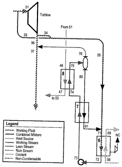
[024] Figure 1 illustrates a turbine seal system according to one embodiment
of
the present invention. In this embodiment, the turbine seal system is utilized
in
connection with an expansion turbine 31-36 of a thermodynamic cycle system.
The
present invention may be utilized in connection with a closed-loop
thermodynamic
system which utilizes a multi-component working fluid, such as a Kalina Cycle
system. While it is understood that the invention may be incorporated into a
variety
of different types of thermodynamic cycle systems, reference will be made
herein
specifically to a Kalina Cycle system. Expansion system 31-36 is utilized to
expand
the high energy working fluid of the thermodynamic system. Expansion of high
energy working fluid enables the potential energy of the working fluid to be
converted into electrical energy. Exemplary Kalina Cycle technologies are
illustrated in U.S. Patent Nos. 5,953,918; 5,5,572,871; 5,440,882 and
4,982,568.
[025] The turbine seal system seals both shaft ends of the expansion turbine
31-
36 with nitrogen at points 31 and 34, utilizing labyrinth or mechanical dry
gas seals.
The labyrinth or mechanical dry gas seals function to reduce the amount
working
fluid that escapes from the expansion turbine. By sealing both ends of the
turbine
with nitrogen, any working fluid which would otherwise escape to the ambient
environment is captured and combined with the nitrogen. The escaped working
fluid having the parameters at point 33 and 34 is thus captured and can be
returned
to the thermodynamic cycle system. This combined mixture of nitrogen and
CA 02604176 2007-10-10
9
WO 2006/124469 PCT/US2006/018118
working fluid will hereinafter be referred to as the combined mixture. The
combined mixtures at points 33 and 34 are combined at a point shortly
downstream
from point 34 and having the parameters at point 35.
[026] The combined mixture at point 35 is evacuated toward a condenser 6.
Shortly before entering condenser 6, the combined mixture is combined with a
lean
stream from point 81 to form the combined mixture at 71. Combined mixture 71
enters condenser 6 having the parameters at point 71. In the condenser, the
combined mixture is provided with an initial degree of condensation intended
to
bring the working fluid to the bubble point.
[027] The combined mixture is condensed utilizing a coolant 58, 59. Coolant
58, 59 enters heat exchanger 6 having a low temperature parameter at point 58
and a
higher temperature parameter at point 59. The transition of the coolant from
the low
temperature parameter 58 to the higher temperature parameter 59 occurs as a
result
of the heat exchange relationship with the combined mixture 71, 72 in heat
exchanger 6. Condenser 6 is utilized to condense the condensable working fluid
of
the combined mixture such that the working fluid has the parameters of point
72.
[028] In connection with condenser 6, non-condensables such as nitrogen from
the combined mixture 71, 72, which are initially provided at both sides of the
turbine
at point 33 and 34, are evacuated to a blowdown tank 5. Blowdown tank 5 is
utilized to prevent the inadvertent release of any remaining working fluid
into
ambient, while allowing for evacuation of the non-condensables, such as
nitrogen.
The use of nitrogen to capture working fluid can allow for both the desired
capture
of escaping working fluid while also providing an environmentally-friendly non-
condensable which can be exhausted to the environment in a safe and effective
manner.
CA 02604176 2007-10-10
WO 2006/124469 PCT/US2006/018118
[029] At point 72, the condensed working fluid comprises a working stream
having parameters at point 72. Working stream 72 is sent to a compressor 73.
At
compressor 72, 73, the working stream 73 is compressed and sent to a heat
exchanger 7. In heat exchanger 7, the working stream is preheated utilizing a
lean
stream 80, 81. The preheated working stream is then sent to a heat exchanger
8.
Heat exchanger 8 utilizes a temperature source fluid 51 from an external heat
source
stream. According to one embodiment of the present invention, the temperature
source fluid comprises fluid from the Kalina Cycle. According to another
embodiment, the temperature source fluid is from a fluid source external to
the
Kalina Cycle and the turbine seal system. The temperature source fluid can
comprise a variety of heat sources such as geothermal brine, industrial waste
heat, or
the like.
[030] In heat exchanger 8, the preheated working stream is heated from a
temperature parameter 74 to a temperature parameter 75. According to one
embodiment of the present invention, the working stream is partially boiled
utilizing
heat exchanger 8. From point 75, the partially boiled working stream enters a
dew
point separator 76-80. Dew point separator 76-80 separates the working stream
into
a rich stream 76 and a lean stream 80. Rich stream 76 may have substantially
the
same pressure and composition as the working fluid or spent stream exiting the
expansion turbine at point 36. In this manner, introduction of the rich stream
76
may not substantially change the balance of the components of the working
fluid of
the Kalina Cycle. Additionally, the pressure and other parameters, such as
composition, of the working fluid from point 36 to point 37 in the Kalina
Cycle can
be maintained.
[031] While the working stream exiting dew point separator at point 76 is
described as a rich streain, it has substantially the same parameters as the
working
CA 02604176 2007-10-10
11
WO 2006/124469 PCT/US2006/018118
fluid or spent stream at point 36. However, with respect to the working stream
at
point 80 (i.e. rich stream), working stream at point 76 (i.e. lean stream) has
substantially more of the low boiling point component of the working stream
than
the working stream at point 80. According to one embodiment of the present
invention, dew point separator 76-80 separates the vapor portion of the
working
stream from the liquid portion of the working stream. The vaporized working
stream is separated to point 76, where it has substantially the same vaporized
characteristics as the working fluid or spent stream at point 36. The liquid
portion or
the lean stream 80 does not have the same temperature parameters as the
working
fluid at point 36.
[032] The lean stream 80 is sent to heat exchanger 7, where it is utilized to
preheat the compressed working stream 73, 74. The heat exchange relationship
between compressed working stream 73-74 and lean stream 80-81 reduces the
temperature of the lean stream to point 81. The cooled lean stream is then
combined
with the combined mixture 35 to provide the combined mixture having the
temperature parameters at point 71. The introduction of the lean stream 81 to
combined mixture 35 can transfer energy from combined mixture 35 to the
components of lean stream 81. In this manner, the energy parameters of the
combined mixture at point 71 are less than the combined mixture at point 35,
thus
facilitating condensation of combined mixture 71 in condenser 6.
[033] The turbine seal system is utilized to both capture vaporized working
fluid that is escaping from turbine 31-36 while also returning such working
fluid to
the Kalina Cycle. The working fluid is returned to the Kalina Cycle having
substantially the same pressure as the working fluid with which it is being
combined
within the Kalina Cycle. Utilizing a gland leakage compressor system minimizes
the escape of the low boiling point component of the working fluid into the
CA 02604176 2007-10-10
12
WO 2006/124469 PCT/US2006/018118
environment. The capture of the low boiling poin.t component can be
particularly
helpful where the chemical properties of the component are harmfiil to the
environment. Additionally, by preventing the loss of working fluid, efficiency
and
conservation of working fluid and, in particular, the low boiling point
component of
the working fluid, is maintained.
[034] According to one embodiment of the present invention, compressor 72-
73 can be controlled to regulate the amount of flow of the condensed working
stream through compressor 72-73. In this manner, the desired vacuum pressure
in
the turbine seal system can be maintained. Controlling the pressure in the
turbine
seal system enables a user to control the parameters of the partially boiled
working
stream at point 75 to follow a desired dew point curve.
[035] The dew point curve is based on a function of pressure and composition
of the working stream and other parameters of the system. In the event that
the
temperature of the working stream needs to be increased, the heating fluid 46-
47 can
be throttled to increase the temperature parameters provided in heat exchanger
8. In
this manner, other changes in parameters within the system can be overcome to
maintain the desired dew point temperature of the partially boiled working
stream at
point 75.
[036] By maintaining the dew point temperature of the working stream, the
working stream is prepared for introduction of the partially boiled working
stream
into the dew point separator 76-80. In other words, flow of a heating fluid 46-
47
and flow of working stream through compressor 72-73 can be utilized to
maintain
desired parameters within the system and to allow for proper functionality of
the
turbine seal system. In particular, the parameters of the working stream at
point 76
can be maintained to approximate the parameters of working fluid or spent
stream at
point 36. Additionally, a desired degree of vacuum can be maintained within
the
CA 02604176 2007-10-10
13
WO 2006/124469 PCT/US2006/018118
turbine seal system to draw the combined mixture through the condenser and the
working stream into the compressor 72-73.
[037] According to one embodiment of the present invention, a desired vacuum
of approximately 30-50 mbar is maintained within the turbine gland
compartment.
This allows for evacuation of a combined mixture from points 33 and 34 and
into
condenser 6. Once the combined mixture has been condensed, the working stream
can be compressed by compressors 72-73, preheated in heat exchanger 7,
partially
boiled in heat exchanger 8, separated by a dew point separator 76-80, and
returned
to the Kalina Cycle system at point 36-37 to provide a working stream having
the
parameters as at point 37.
[038] As will be appreciated by those skilled in the art, a variety of types
and
configurations of compressors can be utilized without departing from the scope
and
spirit of the present invention. According to one embodiment of the present
invention, the turbine seal system of Figure 1 is utilized when the seal
system is air
cooled in an anlbient air temperature of approximately 75 degrees Fahrenheit.
According to another embodiment of the present invention, the turbine seal
system
of Figure 1 is utilized for water cooled plants where the cooling water
temperature is
approximately 85 to 87 degrees Fahrenheit. According to anotller embodiment of
the present invention, the coolant 58-59 utilizes a medium having
approximately a
temperature parameter of no more than 65 degrees Fahrenheit. In other words,
the
turbine seal system of Figure 1 can be utilized where the operating parameters
of the
system are sufficient to maintain desired system operability without
additional
components or systems.
[039] According to another embodiment of the present invention, the turbine
seal system can be utilized in conventional turbine gland seals witllout any
sophisticated or complicated modifications to the existing turbine gland
seals.
CA 02604176 2007-10-10
14
WO 2006/124469 PCT/US2006/018118
According to another embodiment of the present invention, the turbiile seal
system is
utilized with turbine gland seals which are modified in particular for use
with the
turbine seal system.
[040] Figure 2 is a schematic view of a turbine seal system, according to
another embodiment of the present invention. In the illustrated embodiment,
the
turbine seal system includes a heat exchanger 9 and a compressor 79-82. In the
illustrated embodiment, combined mixtures at point 35 are sent to a cooler 9.
Cooler
9 comprises a heat exchanger which reduces the temperature parameters of the
combined mixture at point 35 to a temperature parameter at point 79. The
temperature parameter at point 79 is less than the temperature parameter at
point 35,
decreasing the mechanical power acquired by compressor 79-82. In the
illustrated
einbodiment, a coolant exiting condenser 6 is utilized to cool the combined
mixture
in heat exchanger 9. However, as will be appreciated by one of ordinary skill
in the
art, the coolant utilized in connection with heat exchanger 9 may be separate
and
distinct from coolant in condenser 6.
[041] From point 79, the combined mixture is compressed by a mechanical
compressor 79-82. Mechanical compressor 79-82 compresses the combined
mixture. Increased compression enables condenser 6 to condense the combined
mixture from point 71 to point 72 utilizing the available coolant temperature
of
coolant 58-59. According to one embodiment of the present invention,
mechanical
compressor 79-82 compresses the combined mixture to a maximum compression of
4 to 1, when compared with the compression of the combined mixture at point
79.
Compressing the combined mixture at a compression of 4 to 1 further
facilitates the
desired seal vacuum in the expansion turbine of the Kalina Cycle, even under
extraordinarily hot ambient temperature conditions. Additionally, cooling the
CA 02604176 2007-10-10
WO 2006/124469 PCT/US2006/018118
combined mixture from point 35 to point 39 decreases the mechanical power
needed
for compression utilizing mechanical compressor 79-82.
[042] As will be appreciated by those skilled in the art, cooling of the
combined mixture utilizing heat exchanger 9 and compression utilizing
compressor
79-82 can optionally be bypassed when temperatures parameters within the
system
due not require additional cooling and/or compression of the combined mixture.
For
example, in some systems, normal operating parameters will not require cooling
or
compression of the combined mixture, as provided by heat exchanger 9 and
compressor 79-82. However, occasional adjustments to the system, such as
available coolant temperatures, the return pressure and the main separator 76-
80,
temperature parameter of the combined mixture, or other system variables can
benefit from the additional operability provided by compressor 79-82 and/or
heat
exchanger 9. For example, according to one embodiment of the present
invention,
return pressure in the main separator 76-80 can increase to the point where
the liquid
composition becomes too rich in low boiling point component to condense at the
available coolant temperature. As a result, the additional cooling of the
combined
mixture provided by heat exchanger 9 and/or the compression exerted or
provided
by mechanical compressor 79-82 allows heat exchanger 6 to condense the
combined
mixture at the available coolant temperature parameters of coolant 58-59.
[043] According to another embodiment of the present invention, compressor
79-82 is utilized on an ongoing basis, even when the pressure within the
system
and/or the temperature parameters of the combined mixture is within acceptable
ranges. Utilizing the compressor 79-82 when the operating conditions within
the
system are within normal ranges allows for direct exhausting of the non-
condensables, such as the nitrogen or other fluid utilized to capture the
working fluid
at the expansion turbine even without the use of blowdown tank as is
illustrated in
CA 02604176 2007-10-10
16
WO 2006/124469 PCT/US2006/018118
Figure 1. By allowing for direct exhausting of the system, additional system
components are minimized and/or eliminated to reduce overall system cost and
complexity. As will be appreciated by those skilled in the art, the ability of
the
condenser 6 to condense the combined mixture at point 71-72 is based not only
on
the coolant temperature parameters of coolant 58-59, but also of the
compression of
the combined mixture at point 71.
[044] Once the working stream has been pumped to a higher pressure
parameter at point 73, the working stream enters heat exchanger 7 having
parameters
at point 83. The working stream is preheated to temperature parameters at
point 84
and sent to heat exchanger 8. At heat exchanger 8, the working stream is
partially
boiled and sent to separator 76-80. In separator 76-80, the vapor component of
the
working stream (i.e. rich stream) is separated at point 76 and introduced into
the
Kalina Cycle system at point 36-37, and the liquid portion of the working
stream 80
(i.e. lean stream) is recombined with combined mixture between compressor 79-
82
and condenser 6.
[045] By providing a working stream having substantially the same pressure
and composition as the working fluid or spent stream exiting the expansion
turbine
at point 36, the overall composition and parameters of the working fluid
within a
Kalina Cycle is substantially unchanged. This allows the turbine seal system
to be
utilized without additional system modification or design changes within the
Kalina
Cycle, while at the same time providing the benefits of the turbine seal
system.
[046] As will be appreciated by those skilled in the art, a variety of types
and
configurations of system and system components can be utilized without
departing
from the scope and spirit of the present invention. For example, according to
one
embodiment of the present invention, a pre-condenser coolant heat exchanger is
utilized in the absence of a mechanical compressor. In another embodiment, a
CA 02604176 2007-10-10
17
WO 2006/124469 PCT/US2006/018118
mechanical compressor is utilized in the absence of a pre-condenser coolant
heat
exchanger. In yet another embodiment, one or both of the coolant compressor
and
the heat exchanger can be utilized. In another embodiment, a coolant
compressor is
positioned downstream from the mechanical compressor.
[047] Figure 3 is a schematic view of a turbine seal system, according to
another embodiment of the present invention. In the illustrated embodiment,
the
turbine seal system includes a first separator 76-80 and a second seal
separator 79-
82. Utilizing the first separator and a second separator provides a two-stage
heat-
operated system. This extends the operational range of temperature parameters
of
the combined mixture without utilizing mechanical compression like the
embodiment in Figure 2.
[048] In the illustrated embodiment, compressor 72-73 is utilized to pump the
condensed working stream to a higher pressure than the condensed working
stream
exiting condenser 6. In this embodiment, the temperature parameter of the
working
stream at point 85 exceeds a temperature parameter desired in a typical
setting. As a
result, subsequent to heating of the working stream in heat exchanger 7 and
heat
exchanger 8, the working stream at point 75 has a temperature parameter that
is
higher than the dew point curve.
[049] As the working stream is separated in separator 76-80, the rich stream
may have more of the high boiling point component than the working fluid or
spent
stream at point 36 in the Kalina Cycle. This is largely due to the fact that
the
working stream at point 75 typically exceeds the dew point. As a result, a
larger
portion of the rich stream comprises the low boiling point component than if
the
working fluid was at the dew point. Because the working stream at point 75
exceeds
the dew point, substantially all of the liquid component of the working stream
(i.e.
lean stream) will comprise the high boiling point component. As a result, the
CA 02604176 2007-10-10
18
WO 2006/124469 PCT/US2006/018118
separator liquid at point 80 comprises a lean stream, which can be utilized to
dilute
the combined mixture when mixed with the combined mixture 35 at point 71.
Furthermore, in the illustrated embodiment, lean stream is utilized in heat
exchanger
7 to increase the temperature parameter of working stream from that at point
85 to
that at point 83.
[050] Once the liquid working stream has been separated in separator 76-80,
the rich stream 76 is sent to heat exchanger 9. Heat exchanger 9 comprises a
cooler
which decreases the temperature parameter of the rich stream from point 76 to
point
77. In the illustrated embodiment, the coolant used in heat exchanger 9
comprises a
working fluid from the Kalina Cycle. The working fluid from the Kalina Cycle
cools the rich stream of the turbine seal system, while the rich stream from
point 76
to point 77 heats the working fluid within the Kalina Cycle from point 60 to
point
63. In this manner, not only does the working fluid from the Kalina Cycle
assist in
cooling of the rich stream within the turbine seal system, but the rich stream
from
with the turbine seal system also facilitates heating of the working fluid
within the
Kalina Cycle.
[051] Once the temperature parameter of the rich stream has been cooled from
point 76 to point 77, it is sent to a dew point separator 79-78. Optionally,
the system
can be configured such that the rich stream at point 77 approximates the dew
point.
When the rich stream is at the dew point, substantially more of the vapor
within the
rich stream includes the low boiling point component. In this manner, the
composition and temperature parameters of the rich stream 78 substantially
approximates the composition of the working fluid or spent stream exiting the
turbine at point 36.
[052] The introduction of the rich stream 78 at point 36 minimally effects the
temperature composition of the resulting working fluid 37. In other words, the
CA 02604176 2007-10-10
19
WO 2006/124469 PCT/US2006/018118
composition and temperature parameter of the working fluid at point 37 closely
approximates the temperature and composition of the working fluid or spent
stream
at point 36. However, an increased flow will be provided at point 36 due to
the
addition of rich stream from point 78 at point 36-37.
[053] Dew point separators 79-78 also separates rich stream 77 into a lean
stream 79. Lean stream 79 includes substantially more of the high boiling
point
component than rich stream 78. Lean stream 79 can be pumped utilizing a
compressor 79-82 to return the pressure parameter of lean stream 79 to a point
82.
Additionally, the compression of the lean stream at point 82 approximates the
pressurization parameter of the working stream at point 83. Lean stream 82 is
combined with working stream 83 at point 84 to provide a working stream having
parameters at point 74.
[054] As previously discussed, working stream is sent to heat exchanger 8 to
increase the temperature parameters to point 75. In the illustrated
embodiment, an
external heat source stream 46-47 is utilized in heat exchanger 8 to heat
working
stream 74-75. Due to the higher percentage of high boiling point component in
lean
stream 82, the resulting working stream at point 74 also has more of the high
boiling
point component than the working stream at point 83. As a result, once working
stream 74 has been heated to temperature parameters at point 75 and separated
in
separator 80-76, substantially more of the low boiling point component is
separated
into lean stream 80, providing a sufficient lean stream for dilution at point
81.
[055] The compression provided by compressor 72-73 induces a negative
pressure in condenser 6 relative to point 73, whicll negative pressure draws
the
combined mixture into condenser 6. As a result, adjusting the flow through
compressor 72-73 allows the compressor 72-73 to influence the temperature of
the
working stream at separator 76-80. Similarly, the temperature of the working
stream
CA 02604176 2007-10-10
WO 2006/124469 PCT/US2006/018118
75-74 can be increased by throttling the heat source working stream 46-47 from
heat
source 51.
[056] According to one embodiment of the present invention, the teinperature
of the working stream at point 75 should never fall below the dew point prior
to
being introduced into separator 80-76. This maintains desired species balance
of the
working stream in the turbine seal system in order to provide the desired
composition and temperature parameters of the rich stream at point 78. In the
event
that the temperature parameter of the working stream begins to fall, the rate
of flow
of fluid through compressor 72-73 can be decreased and/or throttling of the
heat
source stream can be effectuated to provide a greater amount of heating of the
working stream within the turbine seal system. For example, in unfavorable
ambient
temperature conditions, the size of the heat exchanger 74-75 and the amount of
heat
consumed therein can be quite large despite a small amount of flow at point
35.
[057] As will be appreciated by those skilled in the art, a variety of types
and
configurations of turbine seal systems can be utilized without departing from
the
scope and spirit of the present invention. For example, according to one
embodiment, a mechanical compressor depicted in Figure 2 can be utilized in
connection with the two-stage, heat-operated system of Figure 3. According to
another embodiment of the present invention, the cooler and/or the compressor
depicted in Figure 2 can be utilized with the two-stage, heat-operated system
of
Figure 3. According to another embodiment, automatic regulation of one or more
parameters within the system can be regulated utilizing a compressor and/or
pump
and a heat source stream flow to regulate operating parameters of the system.
According to another embodiment of the present invention, one or more system
components can be bypassed depending upon operating conditions, such as
temperature parameters of the combined mixture within the system. Furthermore,
CA 02604176 2007-10-10
21
WO 2006/124469 PCT/US2006/018118
the present invention may be incorporated into a variety of different types of
closed
loop thermodynamic cycle systems having multi-component working fluid.
[058] The present invention may be embodied in other specific forms without
departing from its spirit or essential characteristics. The described
embodiments are
to be considered in all respects only as illustrative and not restrictive. The
scope of
the invention is, therefore, indicated by the appended claims rather than by
the
foregoing description. All changes which come within the meaning and range of
equivalency of the claims are to be embraced within their scope.