Note: Descriptions are shown in the official language in which they were submitted.
CA 02604417 2014-05-26
EXIT VALVE FOR BLOWING INSULATION MACHINE
Inventors: Michael W. Johnson, Michael E. Evans, Agustin R. Hernandez,
Robert J.
O'Leary, Christopher M. Relyea, Brian K. Linstedt, Gregory J. Merz, Charles R.
McKean
[0001]
[0002]
TECHNICAL FIELD
[0003] This invention relates to loosefill blowing insulation for
insulating
buildings. More particularly this invention relates to machines for
distributing
packaged loosefill blowing insulation.
BACKGROUND OF THE INVENTION
[0004] In the insulation of buildings, a frequently used insulation
product is
loosefill insulation. In contrast to the unitary or monolithic structure of
insulation batts
or blankets, loosefill insulation is a multiplicity of discrete, individual
tufts, cubes,
flakes or nodules. Loosefill insulation is usually applied to buildings by
blowing the
insulation into an insulation cavity, such as a wall cavity or an attic of a
building.
Typically loosefill insulation is made of glass fibers although other mineral
fibers,
organic fibers, and cellulose fibers can be used.
[0005] Loosefill insulation, commonly referred to as blowing insulation,
is
typically compressed in packages for transport from an insulation
manufacturing site to
a building that is to be insulated. Typically the packages include compressed
blowing
insulation encapsulated in a bag. The bags are made of polypropylene or other
suitable
material. During the packaging of the blowing insulation, it is placed under
1
CA 02604417 2015-03-23
compression for storage and transportation efficiencies. Typically, the
blowing
insulation is packaged with a compression ratio of at least about 10:1. The
distribution
of blowing insulation into an insulation cavity typically uses a blowing
insulation
distribution machine that feeds the blowing insulation pneumatically through a
distribution hose. Blowing insulation distribution machines typically have a
large
chute or hopper for containing and feeding the blowing insulation after the
package is
opened and the blowing insulation is allowed to expand.
[0006] It would be advantageous if blowing insulation machines could be
improved to make them easier to use.
SUMMARY OF THE INVENTION
[0007] According to an aspect, there is provided a machine for
distributing
blowing insulation comprising: a shredding chamber having an outlet end, the
shredding chamber including a plurality of shredders configured to shred and
pick
apart the blowing insulation; a discharge mechanism mounted at the outlet end
of the
shredding chamber, the discharge mechanism configured for distributing the
blowing
insulation into an airstream, the discharge mechanism including a housing and
a
plurality of sealing vane assemblies mounted for rotation, the sealing vane
assemblies
being configured to seal against the housing as the sealing vane assemblies
rotate, the
housing including an eccentric segment extending from the housing, the
eccentric
segment forming a portion of a machine outlet, the machine outlet being
symmetric
about an axis, wherein the axis is parallel to a floor of the machine; and a
blower
configured to provide the airstream flowing through the discharge mechanism;
wherein
the sealing vane assemblies become spaced apart from the housing as the
sealing vane
assemblies rotate through the eccentric segment.
[0008] According to another aspect, there is provided a machine for
distributing
blowing insulation from a bag of compressed blowing insulation, the machine
2
CA 02604417 2015-03-23
comprising: a chute having an inlet end, the inlet end configured to receive
the bag of
compressed blowing insulation; and a shredding chamber associated with the
chute, the
shredding chamber including a plurality of shredders configured to shred and
pick
apart the blowing insulation, the shredding chamber further including a
discharge
mechanism configured for distributing the blowing insulation into an
airstream, the
discharge mechanism having a side inlet and including sealing vane assemblies
having
vane tips, wherein the rotation of the vane tips forms an arc; wherein the
blowing
insulation is fed horizontally from the shredding chamber into the side inlet
of the
discharge mechanism in a manner such that the blowing insulation passes
through the
arc formed by the rotating vane tips, and wherein the discharge mechanism has
a
housing having a diameter, wherein a vertical length of the side inlet is
equal to the
diameter of the housing; a discharge mechanism mounted at the outlet end of
the
shredding chamber, the discharge mechanism having a side inlet and configured
for
distributing the blowing insulation into an airstream; and a blower configured
to
provide the airstream flowing through the discharge mechanism; wherein the
blowing
insulation is fed horizontally from the shredding chamber into the side inlet
of the
discharge mechanism.
[0009]
According to another aspect, there is provided a machine for distributing
blowing insulation comprising: a shredding chamber having an outlet end, the
shredding chamber including a plurality of shredders configured to shred and
pick
apart the blowing insulation; a discharge mechanism mounted at the outlet end
of the
shredding chamber and configured for distributing the blowing insulation into
an
airstream, the discharge mechanism including a housing, an eccentric segment
extending from the housing and an outlet plate, the eccentric segment defining
an
eccentric region, the outlet plate including an outlet opening, the outlet
opening
including the eccentric region and being symmetrical about an axis, wherein
the axis is
parallel to a floor of the machine; and a blower configured to provide the
airstream
3
CA 02604417 2015-03-23
flowing through the discharge mechanism; wherein the outlet opening of the
outlet
plate includes the eccentric region.
[00010] According to another aspect, there is provided a machine for
distributing
blowing insulation from a bag of compressed blowing insulation, the machine
comprising: a shredding chamber having an outlet end, the shredding chamber
including a plurality of shredders configured to shred and pick apart the
blowing
insulation; and a discharge mechanism mounted to the outlet end of the
shredding
chamber and configured for distributing the blowing insulation into an
airstream, the
discharge mechanism including a housing and a plurality of sealing vane
assemblies
mounted for rotation, the sealing vane assemblies being configured to seal
against the
housing as the sealing vane assemblies rotate, the housing having curved
portions and
straight portions, the curved portions extend to form a semi-circle and the
straight
portions extend from the semi-circle formed by the curved portions; and a
blower
configured to provide the airstream flowing through the discharge mechanism;
wherein
the curved portions and straight portions of the housing are configured such
that a
maximum of four sealing vane assemblies seal against the housing at a time.
[00011] According to another aspect, there is provided a machine for
distributing
blowing insulation from a bag of compressed blowing insulation, the machine
comprising: a shredding chamber having an outlet end, the shredding chamber
including a plurality of shredders configured to shred and pick apart the
blowing
insulation; a discharge mechanism mounted at the outlet end of the shredding
chamber
and configured for distributing the blowing insulation into an airstream, the
discharge
mechanism including a plurality of sealing vane assemblies mounted for
rotation, the
sealing vane assemblies including a sealing core and a plurality of vane
support
flanges; and a blower configured to provide the airstream flowing through the
discharge mechanism; wherein the sealing core is supported by opposing vane
support
flanges the vane support flanges being connected to vane support bases,
wherein
4
CA 02604417 2015-03-23
the vane support flanges and the vane support bases combine to form T-shaped
bases.
[00012] Various objects and advantages of this invention will become
apparent to
those skilled in the art from the following detailed description of the
preferred
embodiment, when read in light of the accompanying drawings.
BRIEF DESCRIPTION OF THE DRAWINGS
[00013] Figure 1 is a front view in elevation of an insulation blowing
insulation
machine.
[00014] Figure 2 is a front view in elevation, partially in cross-section,
of the
insulation blowing insulation machine of Figure 1.
[00015] Figure 3 is a side view in elevation of the insulation blowing
insulation
machine of Figure 1.
[00016] Figure 4 is a cross-sectional view in elevation of a discharge
mechanism
of the insulation blowing insulation machine of Figure 1.
[00017] Figure 5 is a perspective view of a shaft lock of the insulation
blowing
insulation machine of Figure 1.
[00018] Figure 6 is a perspective view of a sealing vane assembly of the
blowing
insulation machine of Figure 1.
4a
CA 02604417 2007-09-26
[00019] Figure 7 is a cross-sectional view in elevation of the airstream
and
eccentric region of the blowing insulation machine of Figure 1.
[00020] Figure 8 is a side view in elevation of an end outlet plate of the
blowing
insulation machine of Figure 1.
DETAILED DESCRIPTION OF THE INVENTION
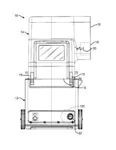
[00021] A blowing insulation machine 10 for distributing blowing
insulation is
shown in Figs. 1-3. The blowing insulation machine 10 includes a lower unit 12
and a
chute 14. The lower unit 12 is connected to the chute 14 by a plurality of
fastening
mechanisms 15 configured to readily assemble and disassemble the chute 14 to
the
lower unit 12. As further shown in Figs.1-3, the chute 14 has an inlet end 16
and an
outlet end 18.
[00022] The chute 14 is configured to receive the blowing insulation and
introduce the blowing insulation to the shredding chamber 23 as shown in Fig.
2.
Optionally, the chute 14 includes a handle segment 21, as shown in Fig. 3, to
facilitate
ready movement of the blowing insulation machine 10 from one location to
another.
However, the handle segment 21 is not necessary to the operation of the
machine 10.
[00023] As further shown in Figs. 1-3, the chute 14 includes an optional
guide
assembly 19 mounted at the inlet end 16 of the chute 14. The guide assembly 19
is
configured to urge a package of compressed blowing insulation against a
cutting
mechanism 20, shown in Figs. 1 and 3, as the package moves into the chute 14.
[00024] As shown in Fig. 2, the shredding chamber 23 is mounted at the
outlet
end 18 of the chute 14. In this embodiment, the shredding chamber 23 includes
a
plurality of low speed shredders 24 and an agitator 26. The low speed
shredders 24
shred and pick apart the blowing insulation as the blowing insulation is
discharged
from the outlet end 18 of the chute 14 into the lower unit 12. Although the
blowing
CA 02604417 2007-09-26
insulation machine 10 is shown with a plurality of low speed shredders 24, any
type of
separator, such as a clump breaker, beater bar or any other mechanism that
shreds and
picks apart the blowing insulation can be used.
[00025] As further shown in Fig. 2, the shredding chamber 23 includes an
agitator 26 for final shredding of the blowing insulation and for preparing
the blowing
insulation for distribution into an airstream. In this embodiment as shown in
Fig. 2,
the agitator 26 is positioned beneath the low speed shredders 24.
Alternatively, the
agitator 26 can be disposed in any location relative to the low speed
shredders 24, such
as horizontally adjacent to, sufficient to receive the blowing insulation from
the low
speed shredders 24. In this embodiment, the agitator 26 is a high speed
shredder.
Alternatively, any type of shredder can be used, such as a low speed shredder,
clump
breaker, beater bar or any other mechanism that finely shreds the blowing
insulation
and prepares the blowing insulation for distribution into an airstream.
[00026] In this embodiment, the low speed shredders 24 rotate at a lower
speed
than the agitator 26. The low speed shredders 24 rotate at a speed of about 40-
80 rpm
and the agitator 26 rotates at a speed of about 300-500 rpm. In another
embodiment,
the low speed shredders 24 can rotate at speeds less than or more than 40-80
rpm and
the agitator 26 can rotate at speeds less than or more than 300-500 rpm.
[00027] Referring again to Fig. 2, a discharge mechanism 28 is positioned
adjacent to the agitator 26 and is configured to distribute the finely
shredded blowing
insulation into the airstream. In this embodiment, the shredded blowing
insulation is
driven through the discharge mechanism 28 and through a machine outlet 32 by
an
airstream provided by a blower 36 mounted in the lower unit 12. The airstream
is
indicated by an arrow 33 in Fig. 3. In another embodiment, the airstream 33
can be
provided by another method, such as by a vacuum, sufficient to provide an
airstream
33 driven through the discharge mechanism 28. In this embodiment, the blower
36
provides the airstream 33 to the discharge mechanism 28 through a duct 38 as
shown
in Fig. 2. Alternatively, the airstream 33 can be provided to the discharge
mechanism
6
CA 02604417 2007-09-26
28 by another structure, such as by a hose or pipe, sufficient to provide the
discharge
mechanism 28 with the airstream 33.
[00028] The shredders 24, agitator 26, discharge mechanism 28 and the
blower
36 are mounted for rotation. They can be driven by any suitable means, such as
by a
motor 34, or other means sufficient to drive rotary equipment. Alternatively,
each of
the shredders 24, agitator 26, discharge mechanism 28 and the blower 36 can be
provided with its own motor.
[00029] In operation, the chute 14 guides the blowing insulation to the
shredding
chamber 23. The shredding chamber 23 includes the low speed shredders 24 which
shred and pick apart the blowing insulation. The shredded blowing insulation
drops
from the low speed shredders 24 into the agitator 26. The agitator 26 prepares
the
blowing insulation for distribution into the airstream 33 by further shredding
the
blowing insulation. The finely shredded blowing insulation exits the agitator
26 at an
outlet end 25 of the shredding chamber 23 and enters the discharge mechanism
28 for
distribution into the airstream 33 provided by the blower 36. The airstream
33, with
the shredded blowing insulation, exits the machine 10 at the machine outlet 32
and
flows through the distribution hose 46, as shown in Fig. 3, toward the
insulation
cavity, not shown.
[00030] As previously discussed and as shown in Fig. 4, the discharge
mechanism 28 is configured to distribute the finely shredded blowing
insulation into
the airstream 33. In this embodiment, the discharge mechanism 28 is a rotary
valve.
Alternatively the discharge mechanism 28 can be any other mechanism including
staging hoppers, metering devices, rotary feeders, sufficient to distribute
the shredded
blowing insulation into the airstream 33.
[00031] As shown in Fig. 4, the discharge mechanism 28 includes a valve
shaft
50 mounted for rotation. In this embodiment, the valve shaft 50 is a hollow
rod having
a hexagonal cross-sectional shape. The valve shaft 50 is configured with flat
hexagonal surfaces 52 which are used to seat a plurality of sealing vane
assemblies 54.
7
CA 02604417 2007-09-26
Alternatively, other cross-sectional shapes, such as a pentagonal cross-
sectional shape,
can be used.
[00032] In this embodiment the valve shaft 50 is made of steel, although
the
valve shaft 50 can be made of other materials, such as aluminum or plastic, or
other
materials sufficient to allow the valve shaft 50 to rotate with the seated
sealing vane
assemblies 54.
[00033] A plurality of sealing vane assemblies 54 are attached to the valve
shaft
50 by positioning them against the flat hexagonal surface 52 of the valve
shaft 50 and
holding them in place by a shaft lock 56. In this embodiment as shown in Fig.
5, the
shaft lock 56 includes a shaft tube 58 having a plurality of slots 60 and
alternate tangs
61. The slots 60 and alternate tangs 61 extend substantially along the length
of the
shaft lock 56. As will be discussed in more detail later, the slot 60 of the
shaft lock 56
slides onto the sealing vane assembly 54 and thereby seats the sealing vane
assembly
54 against the hexagonal surfaces 52 of the valve shaft 50. In another
embodiment,
the valve shaft 50 and the shaft lock 56 may be a single member, such as an
extrusion,
such that the slots 60 slide onto the sealing vane assembly 54 and are thereby
seated
against the hexagonal surfaces 52 of the valve shaft. In this embodiment, the
shaft
lock 56 includes a tube having a plurality of slots 60 and alternate tangs 61.
Alternatively, the sealing vane assemblies 54 could be attached to the valve
shaft 50
by other fastening mechanisms, such as clamps, clips, bolts, sufficient to
attach the
sealing vane assemblies 54 to the valve shaft 50. In this embodiment, the
sealing vane
assemblies 54 are seated against flat hexagonal surfaces 52 of the valve shaft
50 and
fixed by the shaft lock 56. In operation, the machine operator can remove the
sealing
vane assemblies 54, the valve shaft 50 and the shaft lock 56 from the
discharge
mechanism 28 as a unit, thereby making maintenance and repair simpler.
[00034] As previously mentioned, the discharge mechanism 28 includes a
plurality of sealing vane assemblies 54. As shown in Fig. 6, the sealing vane
assemblies 54 include a sealing core 62 disposed between two opposing vane
supports
8
CA 02604417 2007-09-26
64. The sealing core 62 includes a vane tip 68 positioned at the outward end
of the
sealing core 62. As shown in Fig. 4, the sealing vane assembly 54 is
configured such
that the vane tip 68 seals against a valve housing 70 as the sealing vane
assembly 54
rotates within the valve housing 70. In this embodiment, the sealing core 62
is made
from fiber-reinforced rubber. In another embodiment, the sealing core 62 can
be made
of other materials, such as polymer, silicone, felt, or other materials
sufficient to seal
against the valve housing 70. In this embodiment, the fiber-reinforced sealing
core 62
has a hardness rating of about 50 A to 70 A as measured by a Durometer. The
hardness rating of about 50 A to 70 A allows the sealing core 62 to
efficiently seal
against the valve housing 70 as the sealing vane assembly 54 rotates within
the valve
housing 70.
[00035] As further shown in Fig. 6, each vane support 64 includes a vane
support
base 65 and a vane support flange 66. The vane support bases 65 of the
opposing vane
supports 64 combine to form a T-shaped base 69 for each sealing vane assembly
54.
As previously discussed, the T-shaped base 69 seats on the flat hexagonal
surface 52
of the valve shaft 50. The tangs 61 of the shaft lock 56 hold the T-shaped
base 69 of
the sealing vane assembly 54 against the hexagonal surface 52 of the valve
shaft 50.
[00036] In this embodiment as shown in Fig. 6, the sealing core 62 is
attached to
the vane support flanges 66 by a plurality of vane rivets 67. Alternatively,
the sealing
core 62 can be attached to the vane support flanges 66 by sonic welding,
adhesives,
mechanical fasteners, or other fastening methods sufficient to attach the
sealing core
62 to the vane support flanges 66. As shown in Fig. 6, the vane support
flanges 66 are
made of ABS plastic. In another embodiment, the vane support flanges 66 can be
made of other materials, including extruded aluminum or brass, sufficient to
support
the sealing core 62 as the sealing vane assembly 54 rotates within the valve
housing
70.
[00037] Referring again to Fig. 4, the sealing vane assemblies 54,
attached to the
valve shaft 50 by the shaft lock 56, rotate within the valve housing 70. In
this
9
CA 02604417 2007-09-26
embodiment, the valve housing 70 is made from an aluminum extrusion, although
the
valve housing 70 can be made from other materials, including brass or plastic,
sufficient to form a housing within which sealing vane assemblies 54 rotate.
In this
embodiment as shown in Fig. 4, the valve housing 70 includes a top housing
segment
72 and a bottom housing segment 74. In another embodiment, the valve housing
70
can be made of a single segment or the valve housing 70 can be made of more
than
two segments.
[00038] As shown in Fig. 4, the valve housing includes an inner housing
wall 76
and an optional outer housing wall 76a. The inner housing wall 76 having an
inner
housing surface 80. In this embodiment, the inner housing surface 80 is coated
with a
chromium alloy to provide a low friction and extended wear surface.
Alternatively,
the inner housing surface 80 may not be coated with a low friction and
extended wear
surface or the inner housing surface 80 may be coated with other materials,
such as a
nickel alloy, sufficient to provide a low friction, extended wear surface.
[00039] The top housing segment 72 and the bottom housing segment 74 are
attached to the lower unit 12 by housing fasteners 78. In this embodiment, the
housing
fasteners 78 are bolts extending through mounting holes 77 disposed in the top
housing segment 72 and the bottom housing segment 74. In another embodiment,
the
top housing segment 72 and the bottom housing segment 74 can be attached to
the
lower unit 12 by other mechanical fasteners, such as clips or clamps, or by
other
fastening methods including sonic welding or adhesive.
[00040] In this embodiment as shown in Fig. 4, the valve housing 70 is
curved
and extends to form an approximate semi-circular shape. The semi-circular
shape of
the valve housing 70 has an approximate inside diameter d which is
approximately the
same diameter of an arc 71 formed by the vane tips 68 of the rotating sealing
vane
assemblies 54. In operation, the vane tips 68 of the sealing vane assemblies
54 seal
against the inner housing surface 80 such that finely shredded blowing
insulation
CA 02604417 2014-05-26
entering the discharge mechanism 28 is contained within a wedge-shaped space
81
defined by adjacent sealing vane assemblies 54 and the inner housing surface
80.
[00041] As shown in Fig. 4 and 7, the valve housing 70 includes an
eccentric
segment 82. The eccentric segment 82 extends from or bulges out from the semi-
circular shape of the top housing segment 72 and the bottom housing segment
74. In
this embodiment, the eccentric segment 82 has an approximate cross-sectional
shape of
a dome. Alternatively, the eccentric segment 82 can have any cross-section
shape that
extends from the top housing segment 72 and the bottom housing segment 74. The
eccentric segment 82 includes an inner eccentric surface 84. As shown in Fig.
7, the
eccentric segment 82 forms an eccentric region 86 which is defined as the area
bounded by the inner eccentric surface 84 and the arc 71 formed by the vane
tips 68 of
the rotating sealing vane assemblies 54. The eccentric region 86 is within the
airstream 33 flowing through the discharge mechanism 28 and forms a portion of
the
machine outlet 32. In operation, as a sealing vane assembly 54 rotates into
the
airstream 33, the vane tip 68 of the sealing vane assembly 54 becomes spaced
apart
from the inner housing surface 80 of the valve housing 70. As the sealing vane
assembly 54 further rotates within the eccentric region 86, the airstream 33
flows along
the vane tip 68, thereby forcing any particles of blowing wool caught on the
vane tip
68 to be blown off. This clearing of the sealing vane assembly 54 prevents a
buildup
of shredded blowing wool from forming on the sealing vane assembly 54. As
shown
in Fig. 4, the machine outlet 32, including the eccentric region 86, has a
major
dimension mo. The major dimension trio of the machine outlet 32 is symmetric
about
an axis A. In the illustrated embedment, the axis A is parallel to a floor 13
of the lower
unit 12 as best shown in Fig. 2.
[00042] Referring again to Fig. 4, the top and bottom housing segments 72
and
74 do not completely enclose the valve housing 70, and valve housing 70
includes a
side inlet 92. In this embodiment, the side inlet 92 of the valve housing 70
has an
11
CA 02604417 2014-05-26
approximate length equal to the diameter d of the valve housing 70.
Alternatively, the
side inlet 92 of the valve housing 70 can have an approximate length that is
more or
less than the diameter d of the valve housing 70. As shown in Fig. 4 in this
embodiment, the sealing vane assemblies 54, the valve housing 70, the
eccentric region
86 and the side inlet 92 of the valve housing 70 are configured such that as
the sealing
vane assemblies 54 rotate, the vane tips 68 of no more than four sealing vane
assemblies 54 are in contact with the valve housing 70 at any given time. The
remaining vane tips 68 of the sealing vane assemblies 54 are disposed either
in the side
inlet 92 of the valve housing 70 or in the eccentric region 86. By limiting
the number
of sealing vane assemblies 54 in contact with the valve housing 70, the
resulting drag
on the valve shaft 50 is reduced, thereby enabling a minimizing of the size of
the drive
motor 34. In another embodiment, the number of eccentric regions 86 and the
number
of sealing vane assemblies 54, as well as the size of the side inlet 92 can be
varied to
allow more or less sealing vane assemblies 54 to be in contact the valve
housing 70 at
a given time.
1000431 In this embodiment as further shown in Fig. 4, the top housing
segment
72 and the bottom housing segment 74 have optional straight portions 72a and
74a
respectively, extending from the curved portions of the top and bottom housing
segments 72 and 74. The straight portions 72a and 74a are configured such that
as the
sealing vane assemblies 54 rotate, the vane tips 68 are spaced apart from the
straight
portions 72a and 74a. In another embodiment, the top and bottom housing
segments
72 and 74 can have extended segments configured in another shape, such as an
outwardly extending arc, sufficient to be spaced apart from the vane tips 68
as the
sealing vane assemblies 54 rotate.
1000441 As previously discussed and as further shown in Fig. 4, the top
and
bottom housing segments 72 and 74 do not completely enclose the valve housing
70
and the valve housing 70 includes a side inlet 92. The side inlet 92 is
configured to
12
CA 02604417 2014-05-26
receive the finely shredded blowing wool as it is fed from the agitator 26.
Positioning
the side inlet 92 of the discharge mechanism 28 at the side of the discharge
mechanism
28 allows finely shredded blowing wool to be fed approximately horizontally
into the
discharge mechanism 28. Horizontal feeding of the blowing wool from the
agitator 26
to the discharge mechanism 28 is defined to include the feeding of blowing
wool in a
direction that is substantially parallel to the floor 13 of the lower unit 12
as best shown
in Fig. 2. Feeding finely shredded blowing wool horizontally into the
discharge
mechanism 28 allows the discharge mechanism 28 to be positioned at a lower
location
within the lower unit 12, thereby allowing the blowing wool machine 10 to be
more
compact. In this embodiment, the agitator 26 is positioned to be adjacent to
the side
inlet 92 of the discharge mechanism 28. In another embodiment, a low speed
shredder
24, or a plurality of shredders 24 or agitators 26, or another mechanism can
be adjacent
to the side inlet 92, such that finely shredded blowing wool is fed
horizontally into the
side inlet 92.
[00045] The discharge mechanism 28 further includes an end outlet plate
100 as
shown in Figs. 1 and 8. The end outlet plate 100 covers the outlet end of the
discharge
mechanism 28 at the machine outlet 32. The end outlet plate 100 includes
optional
mounting holes 102 and an airstream opening 104. In this embodiment, the
airstream
opening 104 includes the eccentric region 86. In another embodiment, the
airstream
opening 104 can be any shape sufficient to discharge shredded blowing wool
from the
discharge mechanism 28. As shown in Fig. 8, the opening 104, including the
eccentric
region 86, has a major dimension erp. The major dimension erp of the opening
104 is
symmetric about an axis AP. In the illustrated embedment, the axis AP is
parallel to
the floor 13 of the lower unit 12.
1000461 The blowing insulation used with the machine of the present
invention
can be any loose fill insulation, such as a multiplicity of discrete,
individual tuffs,
cubes, flakes, or nodules. The blowing insulation can be made of glass fibers
or other
13
CA 02604417 2014-05-26
=
mineral fibers, and can also be organic fibers or cellulose fibers. Typically,
the loose
fill insulation is made of glass fibers although other insulation materials
such as rock
wool, mineral fibers, organic fibers, polymer fibers, inorganic material, and
cellulose
fibers. Other particulate matter, such as particles of foam, may also be used.
Combinations of any of the aforementioned materials are another alternative.
The
blowing insulation can have a binder material applied to it, or it can be
binderless.
[00047] The
principle and mode of operation of this blowing insulation machine
have been described in its preferred embodiments. However, it should be noted
that
the blowing insulation machine may be practiced otherwise than as specifically
illustrated and described without departing from its scope.
14