Note: Descriptions are shown in the official language in which they were submitted.
CA 02604430 2007-09-26
US20050469-1
METHOD AND APPARATUS FOR TREATING BIOFILM IN AN APPLIANCE
CROSS-REFERENCE TO RELATED APPLICATIONS
[0001] This application is a Continuation-in-Part of U.S. Patent Application
No.
11/599,025, filed November 14, 2006, which is a Continuation-in-Part of U.S.
Patent
Application No. 11/583,559, filed October 19, 2006, both of which are
incorporated
herein by reference in their entirety.
BACKGROUND OF THE INVENTION
Field of the Invention
100021 The invention relates to a method for treating biofilm in an appliance,
such as
a washing machine.
Description of the Related Art
[0003] Biofilm is composed of populations or communities of microorganisms,
which can include bacteria, fungi, archaea, algae, protozoa, and the like. The
microorganisms are encased in protective polymeric compounds called
extracellular
polysaccharide (EPS) excreted by the microorganisms themselves. The EPS is a
slimy,
glue-like substance that helps to anchor the microorganisms to a variety of
surfaces.
Biofilm can develop and grow on any surface exposed to the microorganisms and
moisture. Once formed and adhered to a surface, the biofilm can be difficult
to remove
and potentially destructive to the surface. Common examples of biofilm include
the
plaque on teeth and slime on rocks in rivers, streams, and lakes.
[0004] Some appliances, such as washing machines, fabric
refreshing/revitalizing
appliances, and dishwashers, provide environments conducive to biofilm
formation. For
example, some washing machines may have deposition surfaces in humid spaces
with
little or no air flow. In response to energy and water conservation trends and
legislation
mandates for washing machines, manufacturers have shifted from traditional
deep fill
washing machines to High Efficiency (HE) washing machines, which, depending on
their
-1-
CA 02604430 2007-09-26
US20050469-1
particular structural design and features, may be more susceptible to biofilm
formation if
using low water fills with reduced water temperature and semi-seal low air-
flow internal
environments. Additionally, contrary to the directions in the users manuals
for these
machines, some consumers use standard high sudsing detergents rather than the
recommended low sudsing detergents in the HE washing machines, and the use of
the
former in the HE washing machines can lead to biofilm formation. Moderate to
high
sudsing detergents may create excessive volumes of suds and foam, which float
and
deposit soils and undissolved detergent ingredients onto the surfaces of the
washing
machine. The depositions tend to build up in areas of the washing machine that
are not
submerged and/or flushed with adequate volumes of water during standard use of
the
washing machine and provide a food supply for microorganisms that are airborne
and
introduced into the washing machine with the clothes and accompanying soils.
In the
past, the normal periodic use of bleach in the washing machine to assist in
cleaning the
clothes has inhibited the growth of biofilms, however, some consumers today
avoid the
use of bleach in their wash cycle whenever possible. As a result, biofilm can
form and
grow on the washing machine surfaces, and the biofilm can lead to malodors
emanating
from the appliance and exposure of the clothes load to the microorganisms
during the
wash process.
SUMMARY OF THE INVENTION
[0005] The invention relates to a method for cleaning and sanitizing an
appliance,
including the removal of a biofilm from a cleaning chamber of the appliance.
The
chamber may be heated without liquid in the chamber and then rinsed to remove
all or a
portion of the biofilm.
BRIEF DESCRIPTION OF THE DRAWINGS
[0006] In the drawings:
[0007] Fig. 1 is a schematic view of an exemplary fabric treatment appliance
in the
form of a washing machine according to one embodiment of the invention.
-2-
CA 02604430 2007-09-26
US20050469-1
100081 Fig. 1A is a schematic view of an exemplary controller for the fabric
treatment
appliance of Fig. 1.
[0009] Fig. 2 is a flow chart of a method of treating biofilm in an appliance
according
to one embodiment of the invention.
[0010] Fig. 3 is a flow chart of an exemplary embodiment of the method of Fig.
2 for
use with the fabric treatment appliance of Fig. 1.
[0011] Fig. 4 is a flow chart of a method of treating biofilm in an appliance
according
to another embodiment of the invention.
[0012] Fig. 5 is a flow chart of an exemplary embodiment of the method of Fig.
4 for
use with the fabric treatment appliance of Fig. 1.
100131 Fig. 6 is a flow chart of an exemplary embodiment of the method of Fig.
4 for
use with the fabric treatment appliance of Fig. 1.
DESCRIPTION OF EMBODIMENTS OF THE INVENTION
[0014] The invention provides methods for treatment of the biofilm in
appliances.
The appliance may be any appliance with a moist or wet environment susceptible
to
biofilm formation and growth. Examples of such appliances may include, but are
not
limited to, fabric treatment appliances and dishwashers. The appliances may
have a
cleaning chamber that receives articles, such as clothing and utensils, to be
cleaned. As
used herein "cleaning" and "clean" refer to any processing of the articles
that converts the
articles from one state to another. For example, the cleaning can be washing,
rinsing,
refreshing, revitalizing, sanitizing, drying, treating with a composition,
etc. The chamber
may be defined by a structure, and the structure may provide a surface for
formation and
growth of biofilm.
[0015] Referring now to the figures, Fig. 1 is a schematic view of an
exemplary fabric
treatment appliance in the form of a washing machine 10 according to one
embodiment of
the invention. The fabric treatment appliance may be any machine that treats
fabrics, and
examples of the fabric treatment appliance may include, but are not limited
to, a washing
machine, including top-loading, front-loading, vertical axis, and horizontal
axis washing
-3-
CA 02604430 2007-09-26
US20050469-1
machines; a dryer, such as a tumble dryer or a stationary dryer, including top-
loading
dryers and front-loading dryers; a combination washing machine and dryer; a
tumbling or
stationary refreshing/revitalizing machine; an extractor; a non-aqueous
washing
apparatus; and a revitalizing machine. For illustrative purposes, the
invention will be
described with respect to a washing machine, with it being understood that the
invention
may be adapted for use with any type of appliance having biofilm.
[0016] The washing machine 10 of the illustrated embodiment may include a
cabinet
12 that houses a stationary tub 14. A rotatable drum 16 mounted within the tub
14 may
include a plurality of perforations 18, and liquid may flow between the tub 14
and the
drum 16 through the perforations 18. The drum 16 may further include a
plurality of
baffles 20 disposed on an inner surface of the drum 16 to lift fabric items
contained in the
drum 16 while the drum 16 rotates, as is well known in the washing machine
art. A
motor 22 coupled to the drum 16 through a belt 24 and a drive shaft 25 may
rotate the
drum 16. Alternately, the motor 22 could be directly coupled with the drive
shaft 25 as is
known in the art. Both the tub 14 and the drum 16 may be selectively closed by
a door
26. A bellows 27 couples an open face of the tub 14 with the cabinet 12, and
the door 26
seals against the bellows 27 when the door 26 closes the tub 14. The tub 14,
the door 26,
and the bellows 27 form a structure that defines a cleaning chamber 28 for
receiving
fabric items to be cleaned. The structure may also include other elements in
the chamber
28, such as the drum 16 and the drive shaft 25.
[0017] Washing machines are typically categorized as either a vertical axis
washing
machine or a horizontal axis washing machine. As used herein, the "vertical
axis"
washing machine refers to a washing machine having a rotatable drum, perforate
or
imperforate, that holds fabric items, and a fabric moving element, such as an
agitator,
impeller, nutator, and the like, that induces movement of the fabric items to
impart
mechanical energy to the fabric articles for cleaning action. In some vertical
axis washing
machines, the drum rotates about a vertical axis generally perpendicular to a
surface that
supports the washing machine. However, the rotational axis need not be
vertical. The
drum can rotate about an axis inclined relative to the vertical axis. As used
herein, the
-4-
CA 02604430 2007-09-26
US20050469-1
"horizontal axis" washing machine refers to a washing machine having a
rotatable drum,
perforated or imperforate, that holds fabric items and washes the fabric items
by the
fabric items rubbing against one another as the drum rotates. In horizontal
axis washing
machines, the clothes are lifted by the rotating drum and then fall in
response to gravity to
form a tumbling action that imparts the mechanical energy to the fabric
articles. In some
horizontal axis washing machines, the drum rotates about a horizontal axis
generally
parallel to a surface that supports the washing machine. However, the
rotational axis
need not be horizontal. The drum can rotate about an axis inclined relative to
the
horizontal axis. Vertical axis and horizontal axis machines are best
differentiated by the
manner in which they impart mechanical energy to the fabric articles. In
vertical axis
machines, a clothes mover, such as an agitator, auger, impeller, to name a
few, moves
within a drum to impart mechanical energy directly to the clothes or
indirectly through
wash liquid in the drum. The clothes mover is typically moved in a
reciprocating
rotational movement. The illustrated exemplary washing machine of Fig. 1 is a
horizontal axis washing machine.
[0018] The motor 22 may rotate the drum 16 at various speeds in opposite
rotational
directions. In particular, the motor 22 may rotate the drum 16 at tumbling
speeds wherein
the fabric items in the drum 16 rotate with the drum 16 from a lowest location
of the
drum 16 towards a highest location of the drum 16, but fall back to the lowest
location of
the drum 16 before reaching the highest location of the drum 16. The rotation
of the
fabric items with the drum 16 may be facilitated by the baffles 20. Typically,
the radial
force applied to the fabric items at the tumbling speeds may be less than
about 1 G.
Alternatively, the motor 22 may rotate the drum 16 at spin speeds wherein the
fabric
items rotate with the drum 16 without falling. In the washing machine art, the
spin
speeds may also be referred to as satellizing speeds or sticking speeds.
Typically, the
force applied to the fabric items at the spin speeds may be greater than or
about equal to
1 G. As used herein, "tumbling" of the drum 16 refers to rotating the drum at
a tumble
speed, "spinning" the drum 16 refers to rotating the drum 16 at a spin speed,
and
"rotating" of the drum 16 refers to rotating the drum 16 at any speed.
-5-
CA 02604430 2007-09-26
US20050469-1
[0019] The washing machine 10 of Fig. 1 may further include a liquid supply
and
recirculation system. Liquid, such as water, may be supplied to the washing
machine 10
from a household water supply 29. A first supply conduit 30 may fluidly couple
the water
supply 29 to a detergent dispenser 32. An inlet valve 34 may control flow of
the liquid
from the water supply 29 and through the first supply conduit 30 to the
detergent
dispenser 32. The inlet valve 34 may be positioned in any suitable location
between the
water supply 29 and the detergent dispenser 32. A liquid conduit 36 may
fluidly couple
the detergent dispenser 32 with the tub 14. The liquid conduit 36 may couple
with the tub
14 at any suitable location on the tub 14 and is shown as being coupled to a
front-wall of
the tub 14 in Fig. 1 for exemplary purposes. The liquid that flows from the
detergent
dispenser 32 through the liquid conduit 36 to the tub 14 typically enters a
space between
the tub 14 and the drum 16 and may flow by gravity to a sump 38 formed in part
by a
lower portion 40 of the tub 14. The sump 38 may also be formed by a sump
conduit 42
that may fluidly couple the lower portion 40 of the tub 14 to a pump 44. The
pump 44
may direct fluid to a drain conduit 46, which may drain the liquid from the
washing
machine 10, or to a recirculation conduit 48, which may terminate at a
recirculation inlet
50. The recirculation inlet 50 may direct the liquid from the recirculation
conduit 48 into
the drum 16. The recirculation inlet 50 may introduce the liquid into the drum
16 in any
suitable manner, such as by spraying, dripping, or providing a steady flow of
the liquid.
[0020] The exemplary washing machine 10 may further include a steam generation
system. The steam generation system may include a steam generator 60 that may
receive
liquid from the water supply 29 through a second supply conduit 62. The inlet
valve 34
may control flow of the liquid from the water supply 29 and through the second
supply
conduit 62 to the steam generator 60. The inlet valve 34 may be positioned in
any
suitable location between the water supply 29 and the steam generator 60. A
steam
conduit 66 may fluidly couple the steam generator 60 to a steam inlet 68,
which may
introduce steam into the tub 14. The steam inlet 68 may couple with the tub 14
at any
suitable location on the tub 14 and is shown as being coupled to a rear wall
of the tub 14
in Fig. 1 for exemplary purposes. The steam that enters the tub 14 through the
steam inlet
-6-
CA 02604430 2007-09-26
US20050469-1
68 may subsequently enter the drum 16 through the perforations 18.
Alternatively, the
steam inlet 68 may be configured to introduce the steam directly into the drum
16. The
steam inlet 68 may introduce the steam into the tub 14 in any suitable manner.
[0021] The washing machine 10 may further include an exhaust conduit (not
shown)
that may direct steam that leaves the tub 14 externally of the washing machine
10. The
exhaust conduit may be configured to exhaust the steam directly to the
exterior of the
washing machine 10. Alternatively, the exhaust conduit may be configured to
direct the
steam through a condenser prior to leaving the washing machine 10. Examples of
exhaust systems are disclosed in the following patent applications, which are
incorporated
herein by reference in their entirety: U.S. Patent Application No. 11/464,506,
titled
"Fabric Treating Appliance Utilizing Steam," U.S. Patent Application No.
11/464,501,
titled "A Steam Fabric Treatment Appliance with Exhaust," U.S. Patent
Application No.
11/464,521, titled "Steam Fabric Treatment Appliance with Anti-Siphoning," and
U.S.
Patent Application No. 11/464,520, titled "Determining Fabric Temperature in a
Fabric
Treating Appliance," all filed August 15, 2006.
[0022] The steam generator 60 may be any type of device that converts the
liquid to
steam. For example, the steam generator 60 may be a tank-type steam generator
that
stores a volume of liquid and heats the volume of liquid to convert the liquid
to steam.
Alternatively, the steam generator 60 may be an in-line steam generator that
converts the
liquid to steam as the liquid flows through the steam generator 60. As another
alternative, the steam generator 60 may have a heating element located in the
sump 38 to
heat liquid in the sump 38. The steam generator 60 may produce pressurized or
non-
pressurized steam.
[0023] Exemplary steam generators are disclosed in U.S. Patent Application No.
11/464,528, titled "Removal of Scale and Sludge in a Steam Generator of a
Fabric
Treatment Appliance," U.S. Patent Application No. 11/450,836, titled
"Prevention of
Scale and Sludge in a Steam Generator of a Fabric Treatment Appliance," and
U.S. Patent
Application No. 11/450,714, titled "Draining Liquid From a Steam Generator of
a Fabric
Treatment Appliance," all filed June 9, 2006, in addition to U.S. Patent
Application No.
-7-
CA 02604430 2007-09-26
US20050469-1
11/464,509, titled "Water Supply Control for a Steam Generator of a Fabric
Treatment
Appliance," U.S. Patent Application No. 11/464,514, titled "Water Supply
Control for a
Steam Generator of a Fabric Treatment Appliance Using a Weight Sensor," and
U.S.
Patent Application No. 11/464,513, titled "Water Supply Control for a Steam
Generator
of a Fabric Treatment Appliance Using a Temperature Sensor," all filed August
15, 2006,
which are incorporated herein by reference in their entirety.
[0024] In addition to producing steam, the steam generator 60, whether an in-
line
steam generator, a tank-type steam generator, or any other type of steam
generator, may
heat water to a temperature below a steam transformation temperature, whereby
the steam
generator 60 produces hot water. The hot water may be delivered to the tub 14
and/or
drum 16 from the steam generator 60. The hot water may be used alone or may
optionally mix with cold water in the tub 14 and/or drum 16. Using the steam
generator
to produce hot water may be useful when the steam generator 60 couples only
with a cold
water source of the water supply 29.
[0025] The liquid supply and recirculation system and the steam generation
system
may differ from the configuration shown in Fig. 1, such as by inclusion of
other valves,
conduits, wash aid dispensers, and the like, to control the flow of liquid and
steam
through the washing machine 10 and for the introduction of more than one type
of
detergent/wash aid. For example, a valve may be located in the liquid conduit
36, in the
recirculation conduit 48, and in the steam conduit 66. Furthermore, an
additional conduit
may be included to couple the water supply 29 directly to the tub 14 or the
drum 16 so
that the liquid provided to the tub 14 or the drum 16 does not have to pass
through the
detergent dispenser 32. Alternatively, the liquid may be provided to the tub
14 or the
drum 16 through the steam generator 60 rather than through the detergent
dispenser 32 or
the additional conduit. As another example, the liquid conduit 36 may be
configured to
supply liquid directly into the drum 16, and the recirculation conduit 48 may
be coupled
to the liquid conduit 36 so that the recirculated liquid enters the tub 14 or
the drum 16 at
the same location where the liquid from the detergent dispenser 32 enters the
tub 14 or
the drum 16.
-8-
CA 02604430 2007-09-26
US20050469-1
100261 Other alternatives for the liquid supply and recirculation system are
disclosed
in U.S. Patent Application No. 11/450,636, titled "Method of Operating a
Washing
Machine Using Steam;" U.S. Patent Application No. 11/450,529, titled "Steam
Washing
Machine Operation Method Having Dual Speed Spin Pre-Wash;" and U.S. Patent
Application No. 11/450,620, titled "Steam Washing Machine Operation Method
Having
Dry Spin Pre-Wash," all filed June 9, 2006, which are incorporated herein by
reference in
their entirety.
[0027] Referring to Fig. lA, the washing machine 10 may further include a
controller
70 coupled to various working components of the washing machine 10, such as
the pump
44, the motor 22, the inlet valve 34, the detergent dispenser 32, and the
steam generator
60, to control the operation of the washing machine 10. The controller may
send/receive
electrical signals and/or data to/from the working components to control their
operation
and to execute a desired operation of the washing machine 10.
[0028] The washing machine 10 provides several surfaces that may support the
formation and growth of biofilm. The surfaces most susceptible to biofilm are
those that
are exposed to microorganisms and liquid. For example, the structure that
defines the
chamber 28, which may include the tub 14, the door 26, and the bellows 27, and
the
elements in the chamber 28, such as the drum 16 and the drive shaft 25, may be
exposed
to microorganisms and liquid and thereby function as surfaces to which the
biofilm may
adhere.
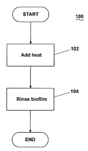
[0029] Fig. 2 is a flow chart of a method 100 of treating biofilm in an
appliance
according to one embodiment of the invention. The method 100 may include a
heating
step 102 and a rinsing step 104, and in the illustrated embodiment, the
heating step 102
occurs prior to the rinsing step 104. In the heating step 102, a heat source
heats the
biofilm and the surface to which the biofilm adheres. Heating the biofilm and
the surface
may have synergistic effects on the biofilm. For example, the heat may loosen
the
biofilm from the surface by reducing the adhesion of the biofilm to the
surface. Because
the heat may loosen the biofilm from the surface, the biofilm may be more
easily
removed during the rinsing step 104, which will be described in more detail
below. At
-9-
CA 02604430 2007-09-26
US20050469-1
the same time, the heat may kill the microorganisms in the biofilm, which may
help
prevent or retard growth of the biofilm and reduce production of the EPS. The
heating of
the surface may be effected by heating the appliance cleaning chamber.
Additionally, the
cleaning chamber may be heated with little or no liquid in the cleaning
chamber to more
effectively, efficiently, and expeditiously heat the chamber and thereby the
surface. With
liquid in the chamber, the heat must heat the liquid along with the chamber
and the
surface, which increases the time and amount of energy needed to heat the
chamber and
the surface. As used in this description, references to the "absence of
liquid", "no liquid"
or "without liquid", and the like, in the chamber does not exclude the
presence of any
liquid in the chamber. In the normal use of the washing machine, there is
often residual
liquid, but for all practical purposes there is no liquid in the tub or drum.
[0030] Heating the surface to a sufficient temperature may effectively
sanitize the
surface. As used herein, "sanitizing" refers to killing, removing, or
otherwise rendering
innocuous all or a portion of the microorganisms in the biofilm. The
sanitizing process
involves heating the surface to a sanitization temperature sufficiently high
to sanitize the
surface. In the sense of sanitizing to kill the microorganisms, the sanitizing
process is a
combination of temperature and time at temperature. Generally, the higher the
temperature, the shorter the time at that temperature needed to kill the
microorganisms.
For the type of microrganisms commonly found in washing machines, there is a
generally
accepted lower temperature of 55 C below which heat alone will not kill the
microorganisms regardless of the length of time the microorganisms are exposed
to these
temperatures. However, if heat is used in combination with a chemistry, such
as chlorine
bleach or oxygenated bleach (a/k/a color safe bleach), lower temperatures can
be used to
sanitize. It is possible to sanitize solely with chemistry, but such a heavy
use of chemistry
may lead to the fabric breaking down more quickly.
[0031] Because of overall cycle time constraints, especially when heat alone
is used
to sanitize, the temperature is normally 60 C or greater. A brief listing of
sanitizing time
and temperatures will aid in understanding. For 100 C, the temperature need
only be
-10-
CA 02604430 2007-09-26
US20050469-1
maintained at about one minute to sanitize. For 70 C, the time is
approximately 7
minutes. For 65 C, the time is approximately 20 minutes. For 55 C, the time
is
approximately one hour. As the temperature decreases and the corresponding
time
increases, there will come a point where the time to sanitize is greater than
the time for
the desired wash cycle, which will require that the wash cycle be extended,
which is
counter to the desire of most consumers, who generally prefer shorter wash
cycles. The
higher temperatures are normally balanced against the energy required to
produce them.
For example, most appliances in the United States have an approximately 115 V
electrical
supply, which inherently limits the wattage of the heater in the steam
generator. In
European countries, 220 V electrical supply is more common. In either case,
there is a
practical consideration on the rate and temperature at which heat or steam can
be
provided.
[0032] To complete the sanitizing within a time acceptable to the consumer, it
has
been determined that temperatures above 60 C should be used. To avoid using
more
exotic or expensive heat systems or steam generators, a preferred range for
the
sanitization temperature may be from about 65 C to about 75 C. Within this
range, it
has been determined that an exemplary suitable sanitization temperature is
about 70 C.
These ranges and specific temperatures have been found to address the overall
cycle times
and the heating requirements for current washers.
[0033) After the heating step 102, the biofilm may be rinsed from the cleaning
chamber with liquid in the rinsing step 104. Rinsing the biofilm may remove
the biofilm
previously loosened and/or killed during the heating step 102. The rinsing may
include
introducing liquid at a flow rate sufficient to mechanically remove the
biofilm from the
surface. Furthermore, the liquid may submerge at least a portion of the
surface to "soak"
the biofilm and facilitate removal of the biofilm from the surface. Depending
on the type
of appliance, the liquid may be agitated within the chamber to aid in physical
removal of
the biofilm. Optionally, the liquid may include a pesticide, such as an
antimicrobial,
biocide, disinfectant, and sanitizer that may kill or otherwise treat the
biofilm. Exemplary
-11-
CA 02604430 2007-09-26
US20050469-1
pesticides include bleaches, such as peroxide bleaches; other oxidizing
chemicals;
Microban chemicals; and silver, copper, and zinc ions. A pesticide may also be
introduced during the heating step 102, but some chemicals, such as chlorine
bleach, may
be negatively affected by the heat (e.g., the heat may weaken the bleach
and/or make the
bleach corrosive). The rinsing step 104 may be repeated a predetermined number
of
times to ensure sufficient removal of the biofilm from the chamber.
[0034] The method 100 may be adapted for use in any suitable appliance, and
Fig. 3
is a flow chart of an exemplary embodiment of the method 100 of Fig. 2 for use
with the
exemplary washing machine 10 of Fig. 1. The heating step 102 may include a
steam
introduction step 106 whereby steam may be introduced into the chamber 28. The
steam
may be generated in the steam generator 60 from water supplied by the water
supply 29
through the second supply conduit 62. The steam may be introduced into the
chamber 28
through the steam conduit 66 and the steam inlet 68. The heating of the
chamber 28 with
the steam results in heating the structure that defines the chamber 28 and any
elements in
the chamber 28. For the illustrated embodiment, heating the chamber 28 may
result in
heating the tub 14, the drum 16, the drive shaft 25, the door 26, and the
bellows 27 and
any biofilm residing on these components. Because the components are each
exposed to
the steam, including the components in hard to reach places, such as the drive
shaft 25
and a back side of the drum 16, the components may be uniformly heated to a
desired
temperature. Optionally, the steam may be introduced into the chamber 28 at
high
pressure to aid in physical removal of the biofilm from the surface. As
another option, a
pesticide or other chemical may be introduced into the chamber 28 with the
steam, as
described in more detail in U.S. Patent Application No. 11/583,559, titled
"Washer with
Bio Prevention Cycle," filed October 19, 2006, which is incorporated herein by
reference
in its entirety.
[0035] The steam may be introduced continuously or according to a duty cycle
until
the temperature of the chamber 28 reaches a predetermined temperature, such as
the
sanitization temperature. The temperature of the chamber 28 may be determined
in any
suitable manner. For example, the temperature of the chamber 28 may be
determined
-12-
CA 02604430 2007-09-26
US20050469-1
with a temperature sensor positioned at or near the exhaust conduit for the
tub 14, as
described in more detail in the aforementioned and incorporated U.S. Patent
Application
No. 11/464,520. The heating of the chamber 28 may be executed with little or
no liquid
in the chamber 28 such that the heating of the chamber 28 and the structure
occurs
relatively fast with a relatively low thermal load, as compared to heating the
chamber 28
and the structure with liquid in the chamber 28.
[0036] After the chamber 28 reaches the predetermined temperature, the steam
may
be introduced as needed to maintain the predetermined temperature for a
predetermined
time. The predetermined time may be an empirically determined time and may be
a time
corresponding to sufficient heating of the structure on which the biofilm
resides and/or a
time corresponding to sufficient loosening or killing of the biofilm. An
exemplary
predetermined time may be about 10 minutes.
100371 Other heating devices may be used in place of the steam generator 60. A
sump heater 52 could be used to heat the chamber 28. The sump heater 52 can
heat the
chamber 28 by direct radiation, heating water in the sump, or by generating
steam from
water in the sump. The sump heater 52 can be used in combination with the
steam
generator 60 to achieve a faster rate of heater and/or a higher temperature in
the chamber.
100381 It should be noted that while reference is made to heating the chamber
28,
since the drum 16 resides in the chamber 15 of the tub 14, any heating of
either chamber
15, 28, will necessarily result in the heating of the other chamber. Thus, to
heat one of
the chambers 15, 28, one could directly heat the chamber 15, 28 or indirectly
heat it by
heating the other chamber 15, 28. Any reference to heating a chamber in this
application
necessarily includes both a direct and indirect heating of the chamber.
[0039] Optionally, the heating step 102 may include drum rotation, such as
during the
steam introduction step 106. Rotation of the drum 16 during the introduction
of steam
aids in a more even distribution of steam throughout the chamber 28. As a
result, the
steam may be more easily distributed and may be evenly distributed in the
chamber 28
regardless of the location of the steam inlet 68. Further, drum rotation may
function to
retain the steam in the chamber 28 rather than rising and leaking from the
chamber 28
-13-
CA 02604430 2007-09-26
US20050469-1
through any air passages, such as the aforementioned exhaust conduit, coupled
to the
chamber 28. The rotation of the drum tends to cause the steam to circulate
with the
chamber instead of naturally rising and escaping through any available
openings. Also,
some washers have a safety vent that is open whenever the drum is stopped,
which
provides an air path in case someone enters the washer and shuts the door,
such as a
child. When the drum rotates, the safety vent is closed, eliminating a conduit
through
which the steam can escape.
[0040] The drum 16 may rotate in any suitable manner; the drum 16 may rotate
at
tumbling speeds and/or spinning speeds, and the drum 16 may rotate in one
direction or
alternating directions. As an example, the drum 16 may rotate at tumbling
speeds in
alternating directions. An exemplary tumbling speed may be about 40 rpm. In a
vertical
axis washing machine, the fabric moving element may rotate instead of or in
addition to
rotation of the drum 16. The drum 16 may rotate for a predetermined time,
which may be
empirically determined. The drum 16 may rotate continuously or intermittently
during
the steam introduction step 106 and may rotate before the steam introduction
step 106
initiates and/or after the steam introduction step 106 terminates.
[0041] Following the steam introduction step 106, the rinsing step 104 may
begin
with a liquid introduction step 108. The liquid introduction step 108 may
include
introducing water from the water supply 29 into the chamber 28 through the
first supply
conduit 30, the detergent dispenser 32, and/or the liquid conduit 36. The
water may be
introduced until the water reaches a predetermined level in the chamber 28.
According to
one embodiment, the predetermined level in the chamber 28 may be less than a
level
corresponding to submerging the drum 16 with the water. The predetermined
level may
be selected to ensure sufficient liquid agitation during a subsequent drum
rotation step
110 yet avoid excessive drag on the drum 16 during the rotation of the drum 16
and
leakage of the liquid through the door 26.
[0042] Optionally, a pesticide may be introduced into the chamber 28 with the
water.
For example, the detergent dispenser 32 may hold a supply of the pesticide,
and the water
may mix with the pesticide as the water flows through the detergent dispenser
32.
-14-
CA 02604430 2007-09-26
US20050469-1
Alternatively, the water may flow through another wash aid dispenser, such as
a bleach
dispenser holding a supply of bleach. The water may be any suitable
temperature; heated
water may be used to aid in sanitizing the structure. When the water and a
pesticide
negatively affected by heat are present in the chamber 28 at the same time,
the water may
be cold water to avoid destroying the efficacy of the pesticide and/or
rendering the
pesticide corrosive. Because the heating step 102 occurs prior to the liquid
introduction
step 108 and treats the biofilm, less pesticide may typically be used compared
to a method
without the heating step 102 (i.e., less pesticide may be needed to effect
sufficient
treatment of the biofilm). 10 [0043] The drum rotation step 110 may follow the
liquid introduction step 108 and/or
may be executed during the liquid introduction step 108. During the drum
rotation step
110, the motor 22 rotates the drum 16 to induce agitation of the liquid in the
chamber 28.
The agitation of the liquid helps to physically remove the biofilm from the
structure. The
drum 16 may rotate in any suitable manner; the drum 16 may rotate at tumbling
speeds
and/or spinning speeds, and the drum 16 may rotate in one direction or
alternating
directions. As an example, the drum 16 may rotate at spinning speeds in
alternating
directions. An exemplary spinning speed may be about 150 rpm. In a vertical
axis
washing machine, the fabric moving element may rotate instead of or in
addition to
rotation of the drum 16. The drum 16 may rotate for a predetermined time,
which may be
empirically determined. Optionally, the liquid in the chamber 28 may be
recirculated
through the pump 44 and the recirculation conduit 48 during the liquid
introduction step
108 and the drum rotation step 110.
[0044] After the drum rotation step I 10, the liquid in the chamber 28 may be
drained
during a liquid draining step 112. The liquid may be drained from the sump 38
through
the pump 44 and the drain conduit 46. Optionally, the liquid draining step 112
may
include rotation, tumbling and/or spinning, of the drum 16 to aid in drying
liquid residue
in the chamber 28. The rotation of the drum 16 may occur during the draining
of the
liquid or can follow the draining of the liquid. Drying the liquid residue
helps prevent
formation and growth of biofilm following execution of the method 100.
-15-
CA 02604430 2007-09-26
US20050469-1
[0045] The method 100 may end after the liquid draining step 112, or the
heating step
102 and/or the rinsing step 104 may be repeated a desired number of times.
100461 The method 100 may be executed as a stand-alone cycle or may
incorporated
into another cycle of the appliance. For example, the method 100 may be
incorporated
into a wash cycle or a sanitization cycle, such as the sanitization cycle
disclosed in U.S.
Patent Application No. 11/464,507, titled "Method of Sanitizing a Fabric Load
with
Steam in a Fabric Treatment Appliance," filed August 15, 2006. The method 100
may be
automatically executed by the appliance, such as at preprogrammed time
periods, or may
be executed manually by a user.
100471 The method 100 may be executed in any suitable order. For example, the
heating step 102 and the rinsing step 104 may be executed in reverse order, as
illustrated
in Fig. 4, which is a flow chart of a method 100A of treating biofilm in an
appliance
according to another embodiment of the invention. In Fig. 4, the steps of the
method
100A are identical to those of the method 100 of Fig. 2 and are identified the
with same
reference numerals bearing the letter "A." Fig. 5 is a flow chart of an
exemplary
embodiment of the method of Fig. 4 for use with the washing machine 10 of Fig.
1. In
Fig. 5, the steps of the method 100A are identical to those of the method 100
of Fig. 3 and
are identified the with same reference numerals bearing the letter "A."
[0048] The method 100 may include any number of the heating step 102 and the
rinsing step 104 in any desired order to achieve a desired treatment of
biofilm. For
example, the heating step 102 can both precede and follow the rinsing step
104, as
illustrated in Fig. 6, which is a flow chart of a method 100B of treating
biofilm in an
appliance according to another embodiment of the invention. In Fig. 6, the
heating step
102B and the rinsing step 104B of the method 100B are identical to those of
the method
100 of Fig. 2. Performing a final heating step 102B after an initial heating
step 102B and
the rinsing step 104B may treat any biofilm not completely removed or
otherwise treated
during the initial heating step 102B and the rinsing step 104B. The final
heating step
102B may be especially beneficial if a large amount of biofilm is present
prior to
execution of the method 100B or if the biofilm is sufficiently thick such that
the initial
-16-
CA 02604430 2007-09-26
US20050469-1
heating step 102C and the rinsing step 104B cannot access the entire thickness
of the
biofilm. During the final heating step 102B, the heat may loosen the remaining
biofilm
from the surface by reducing the adhesion of the biofilm to the surface and
may kill the
microorganisms in the biofilm.
100491 While the invention has been specifically described in connection with
certain
specific embodiments thereof, it is to be understood that this is by way of
illustration and
not of limitation, and the scope of the appended claims should be construed as
broadly as
the prior art will permit.
-17-
CA 02604430 2007-09-26
US20050469-1
PARTS LIST
washing machine 56
12 cabinet 58
14 tub 60 steam generator
16 drum 62 second supply conduit
18 perforations 64
baffles 66 steam conduit
22 motor 68 steam inlet
24 belt 70
drive shaft 72
26 door 74
27 bellows 76
28 cleaning chamber 78
29 household water supply 80
first supply conduit 82
32 detergent dispenser 84
34 inlet valve 86
36 liquid conduit 88
38 sump 90
tub lower portion 100 method
42 sump conduit 102 heating step
44 pump 104 rinsing step
46 drain conduit 106 steam introduction step
48 recirculation conduit 108 liquid introduction step
recirculation inlet 110 drum rotation step
52 112 liquid draining step
54 114
G0297621
-23-