Note: Descriptions are shown in the official language in which they were submitted.
CA 02604642 2007-09-28
REINFORCED GROUND COVER MATS
FIELD OF THE INVENTION
The present invention relates to ground cover mats.
BACKGROUND OF TIiE INVENTION
In the oil and gas industry, it is sometimes necessary to provide ground cover
mats with
sufficient strength to support heavy equipment and transport trucks over wet
or disturbed ground.
Several prior art ground cover mats exist; however, they lack sufficient
reinforcement to
withstand the pressure of heavy equipment and transport trucks, and are
expensive to produce.
What is needed is an improved ground cover mat which is simple and relatively
inexpensive and
has sufficient strength and durability to support heavy equipment.
Further, ground cover mats tend to be extremely heavy and lengthy, making the
mats
difficult to store, lift, transport, assemble or disassemble. Since a series
of mats are generally
required to construct a temporary road, an improved ground cover mat which is
easy to handle is
desirable.
There have been attempts in the prior art to solve such problems. For example,
United
States Patent No. 4,462,712 issued July 31, 1984 to Penland, Sr. describes an
interlocking mat
assembly comprising assemblies of two-ply laminated mats which interlock and
are secured
together by nailing a top layer of planks over the interlocked mats. However,
this mat assembly
is particularly labor intensive.
Canadian Patent No. 1,285,166 issued June 25, 1991 to Pouyer describes a
temporary
road which includes a plurality of sets, each defined by upper and lower
matrices with the upper
matrices comprising boards and the lower matrices comprising cross-support
members for
CA 02604642 2007-09-28
supporting the boards. The road is constructed by interlocking series of sets
in a superimposed
assembly, necessitating significant redundancy of effort in assembly and
disassembly.
United States Patent No. 6,695,527 issued February 24, 2004 to Seaux et al,
describes
interlocking mats constructed of two mirror half pieces which are joined
together to form a
complete single mat containing an internal cellular structure. Traction
promoting elements in the
form of raised strips extending outward from the planar surfaces of the mats
and aligned with the
internal cell forming walls are provided to improve traction and to absorb
heavy loading from
vehicles and equipment. However, Seaux et al. indicates that when a large
number of the raised
strips are not specifically positioned in such a manner, the relatively thin
outer skin defining the
roughly planar surfaces of the mats can become easily deformed by such direct
loading.
United States Patent Nos. 4,600,336 and 5,087,149 issued July 15, 1986 and
February 11,
1992 respectively, to Waller describe mat systems having individual mats with
altemating offset
extensions and recesses along the edges. These systems are disadvantageous in
that the offset
extensions are comprised of individual planks which may be subject to warping
or splintering
when exposed to heavy loads. Further, the offset extensions need to be nailed
in place to be
secured within the recess of an adjacent mat. An extra plank is secured over
the exposed nailed
joints of adjacent mats to interlock the mat assemblies together as a roadway,
which significantly
increases material and labor requirements.
Canadian Patent No. 2,348,328 issued October 22, 2002 to Stasiewich et al
describes a
road mat including, at both of its ends, couplings having retaining lips which
engage
complimentary retaining lips of adjacent mats to prevent separation when
weight applied by a
vehicle to one road mat is transferred to an adjacent road mat. Canadian
Patent No. 2,364,968
issued June 22, 2004 to Stasiewich et al describes a road mat having end and
side interlocks to
secure adjacent mats. However, there is no provision in either patent of
details regarding
attachment of the retaining lips to the mat ends, or the use of any
reinforcing structural support.
2
CA 02604642 2007-09-28
The present invention addresses the above shortcomings of the prior art,
meeting the need
for an improved ground cover mat which has sufficient strength to support
heavy equipment,
provides easy handling, and is simple and relatively inexpensive.
SUMMARY OF THE INVENTION
The present invention is directed to ground cover mats. In one aspect of the
invention,
the invention comprises a ground cover mat comprising:
(a) a quadrilateral frame comprised of:
(i) two substantially parallel opposing end members, each such end member
having an inner slot facing the opposing end member and an outer slot facing
away from the opposing end member; and
(ii) two substantially parallel opposing lateral members;
whereby the four corners of the quadrilateral frame comprise a joint between
one
end of a lateral member and one end of an end member;
(b) a plurality of elongate boards retained within the frame, the frame and
the boards
collectively forming two opposing major surfaces, and whereby said boards
insert
into, and are retained by the inner slots of the end members; and
(c) a tubular member attached at each end of the mat, whereby each tubular
member
inserts into, and is retained by the outer slots of the end members.
In one embodiment, each end member is an I-beam comprising a vertical web and
upper
and lower horizontal flanges connected to opposite ends of the vertical web,
said horizontal
flanges and vertical web forming the inner and outer slots. In one embodiment,
each lateral
member has a slot facing the opposing lateral member, and wherein the elongate
boards insert
into, and are retained by the slots in the lateral members. In one embodiment,
the tubular
members are longer than the end members and project beyond each end of the end
members, and
wherein each end of the tubular member has a flanged cap extending beyond the
diameter of the
3
CA 02604642 2007-09-28
tubular member. In one embodiment, the end of each tubular member is tapered
such that there
is a gap between the tubular member and one of the major surfaces. In one
embodiment, a recess
in the ends of each lateral member allows access to the flange capped ends of
the tubular
members. In one embodiment, at least one of the horizontal flanges forming the
outer slot of
each end member is bent at an angle towards the opposing horizontal flange.
In one embodiment, the boards are retained within the frame in an orientation
that is
substantially parallel to the end members. In one embodiment, the boards are
retained within the
frame in an orientation that is substantially perpendicular to the end
members. In one
embodiment, each elongate board comprises a board having a substantially
rectangular cross-
section and disposed such that the vertical dimension is larger than the
horizontal dimension. In
one embodiment, each elongate board comprises at least one wood layer bonded
to at least one
composite material layer.
In one embodiment, a mid rail comprises a structural support member being
connected at
each end to the mid point of each end member in an orientation that is
substantially parallel to
each lateral member. In one embodiment, the ends of the mid rail insert into,
and are retained by
the inner slots of the end members. In one embodiment, the mid rail has slots
facing the lateral
members, and wherein the elongate boards insert into, and are retained by the
slots on the mid
rail. In one embodiment, a plurality of cross-beam support members are
arranged in an
orientation that is substantially parallel to the opposing end members, each
cross-beam support
member being connected at one end to the mid rail and at the other end to a
lateral member.
In a further embodiment, the mat comprises means for lifting disposed on one
of the
major surfaces. In one embodiment, the means for lifting comprises at least
two passages, each
such passage extending from an opening on a major surface proximate to a
lateral member, to an
opening in the outer surface of the lateral member. In one embodiment, the
means for lifting
comprises a lifting shackle assembly, the assembly comprising a lifting
shackle, closure means, a
front wall, and parallel spaced outer and inner side walls which extend from
the front wall and
are spaced apart at a distance sufficient to accommodate the lifting shackle.
In one embodiment,
the outer side wall has an attachment plate protruding outwardly from its
upper surface for
holding a board or a cross-beam member. In one embodiment, the inner side wall
has a
4
CA 02604642 2007-09-28
thickness greater than that of the outer side wall, and a bore through which
the closure means can
extend to anchor the lifting shackle. In one embodiment, the lifting shackle
is generally U-
shaped, having a bow portion and arms with eyelets for insertion of the
closure means. In one
embodiment, the closure means is selected from a screw pin, a round pin, an
alloy screw pin, an
alloy round pin, or a bolt and nut with a cotter pin.
In yet a further embodiment, the means for lifting comprises a pear link
assembly, the
assembly comprising a pear link, two opposing side walls, a retaining bar
anchored between the
opposing side walls, and two opposing end walls, the side wall defining a bore
which aligns with
a complimentary bore on the opposing side wall for insertion of the retaining
bar, and the pear
link being pivotally mounted on the retaining bar. In one embodiment, the side
wall has a notch
formed therein for allowing drainage of water or mud.
BRIEF DESCRIPTION OF THE DRAWINGS
The invention will now be described by way of an exemplary embodiment with
reference
to the accompanying simplified, diagrammatic, not-to-scale drawings.
Figure 1 is a diagrammatic representation of a mat of one embodiment of the
present
invention.
Figure la is a cross-sectional view taken along line la-la of Figure 1,
showing the detail
of an I-beam and a tubular member.
Figure lb is an enlarged view of a partially cut away section of a mat of
Figure 1,
showing the detail of a board, an I-beam and a tubular member.
Figure lc is a diagrammatic representation of a partially cut away section of
a mat,
showing the detail of a plurality of cross-beam members, an I-beam and a
tubular member.
Figure 2 is a diagrammatic representation of a side view of a tubular member
of one
embodiment of the present invention.
Figure 3 is a diagrammatic representation of a side view of a tubular member
of one
5
CA 02604642 2007-09-28
embodiment of the present invention.
Figure 4 is a diagrammatic depiction of a portion of an end member of one
embodiment
of a mat of the present invention.
Figure 5 is a diagrammatic representation of a top view of a portion of an end
member of
one embodiment of the present invention.
Figure 6 is a diagrammatic representation of a side view of the end portion of
a tubular
member of one embodiment of the present invention.
Figure 7 is a diagrammatic representation of a side view of the end member and
a portion
of a lateral member of one embodiment of the present invention.
Figure 8 is a diagrammatic depiction of one embodiment of a mat of the present
invention.
Figure 8a is an enlarged view of a partially cut away section of a mat of
Figure 8,
showing the detail of a left lifting shackle assembly.
Figure 8b is a cross-sectional view taken along line 8b-8b of Figure 8a,
showing the
detail of the left lifting shackle assembly.
Figure 8c is an enlarged view of a partially cut away section of a mat of
Figure 8,
showing the detail of a right lifting shackle assembly.
Figure 8d is a cross-sectional view taken along line 8d-8d of Figure 8c,
showing the
detail of the right lifting shackle assembly.
Figure 9 is a diagrammatic depiction of one embodiment of a mat of the present
invention.
Figure 9a is an enlarged view of a partially cut away section of a mat of
Figure 9,
showing the detail of a left pear link assembly.
Figure 9b is an enlarged view of a partially cut away section of a mat of
Figure 9,
6
CA 02604642 2007-09-28
showing the detail of a right pear link assembly.
DETAILED DESCRIPTION OF THE INVENTION
The present invention provides for reinforced ground cover mats. When
describing the
present invention, all terms not defined herein have their common art-
recognized meanings. To
the extent that the following description is of a specific embodiment or a
particular use of the
invention, it is intended to be illustrative only, and not limiting of the
claimed invention. The
following description is intended to cover all alternatives, modifications and
equivalents that are
included in the spirit and scope of the invention, as defined in the appended
claims.
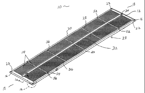
The invention will now be described having regard to the accompanying Figures.
The
mat (10) is comprised of a quadrilateral frame (12), a plurality of elongate
boards (14) and a
tubular members (16).
The quadrilateral frame (12) comprises two substantially parallel opposing end
members
(18) and two substantially parallel opposing lateral members (20). The four
comers of the frame
(12) comprise a joint (22) between one end of a lateral member (20) and one
end of an end
member (18). Each end member (18) has an inner slot (24) facing the opposing
end member
(18) and an outer slot (26) facing away from the opposing end member (18).
Each lateral
member (20) has a slot (not shown) facing the opposing lateral member (20).
The elongate
boards (14) insert into, and are retained by the slots (not shown) in the
lateral members (20).
The elongate boards (14) are retained within the frame (12). The frame (12)
and the
boards (14) collectively form two opposing major surfaces (28). The boards
(14) insert into, and
are retained by the inner slots (24) of the end members (18), as shown in
Figure la. The tubular
member (16) is attached at each end of the mat (10) in an orientation parallel
to the end member.
Each tubular member (16) inserts into, and is retained by the outer slots (26)
of the end members
(18).
In one embodiment, the boards (14) are retained within the frame (12) in an
orientation
that is substantially perpendicular to the end members (18) (Figures 1 and
lb). In one
embodiment, each board (14) has a substantially rectangular cross-section and
is disposed such
7
CA 02604642 2007-09-28
that the vertical dimension of the board (14) is larger than the horizontal
dimension, thus
increasing the bending strength of the mat (10). The boards (14) may be single
2x4 or 2x6
boards or may be constructed using wood layers bonded to composite material
layers. In one
embodiment, the board comprises at least one wood layer bonded to at least one
composite
material layer. As used herein, the term "composite" refers to any engineered
material made
from two or more constituent materials with significantly different physical
or chemical
properties and which remain separate and distinct on a macroscopic level
within the finished
structure. In one embodiment, the composite material layers may comprise
fiberglass; however,
such other materials as are commonly used in the art may also be employed for
the boards (14).
In another embodiment, the boards (14) are retained within the frame (12) in
an
orientation that is substantially parallel to the end members (18). In one
embodiment, the boards
(14) are constructed from a plurality of cross-beam members (30) arranged in
an orientation that
is parallel to the end members (18) (Figure lc). The cross-beam members (30)
may be
constructed of single 6x6 timbers or other suitable materials as are commonly
used in the art.
The frame (12) is constructed from any suitable material such as steel. The
frame (12)
includes a mid rail (32) comprising a structural support member (34) which is
connected at each
end to the mid point of each end member (18) in an orientation that is
substantially parallel to
each lateral member (20). The ends of the mid rail (32) insert into, and are
retained by the inner
slots (24) of the end members (18). The mid rail (32) has slots (not shown)
facing the lateral
members (20). The boards (14) insert into, and are retained by the slots (not
shown) on the mid
rail (32). A plurality of cross-beam support members (36) are arranged in an
orientation that is
substantially parallel to the opposing end members (18). Each cross-beam
support member (36)
is connected at one end to the mid rail (32) and at the other end to a lateral
member (20). Means
for lifting the mat are disposed on one of the major surfaces (28).
The mat (10) is specially configured at its end members (18) to provide
strength and to
enable easy stacking of adjacent mats (10) as described below.
As shown in Figures 1, 4 and 5, each end member (18) is an I-beam (38)
comprising a
vertical web (40) and upper and lower horizontal flanges (42, 44) connected to
opposite ends of
8
CA 02604642 2007-09-28
the vertidal web (40). The upper and lower horizontal flanges (42, 44) and
vertical web (40)
form the inner and outer slots (24, 26). The upper and lower horizontal
flanges (42, 44)
correspond to the top and bottom horizontal portions of the letter "I" as
viewed in cross section
in Figure la. As used herein, the terms "upper" and "lower" refer to the I-
beam when in the
orientation shown for example in Figure 1a. However, the artisan will
recognize that the I-beam
can adopt any particular orientation when in use.
The I-beam (38) is sized to accommodate the board (14) or cross-beam members
(30),
and the tubular member (16) accordingly. The I-beam (38) has a length which
does not extend
past the edges of the lateral members (20) or the length of the tubular member
(16). In one
embodiment, the width of the I-beam (38) is substantially identical to the
width of the board (14),
as shown in Figures 1 and la. In one embodiment, the board (14) may be notched
(14a) to
accommodate the I-beam (38) when the width of the I-beam (38) is less than the
width of the
board (14), as shown in Figures 4 and 5. The I-beam (38) may be formed of
structural steel or
other suitable materials commonly used in the art.
The I-beam (38) is positioned in an orientation substantially parallel to the
respective end
member (18) and perpendicular to the lateral members (20) so as to encase the
board (14) (see
Figure 1b) or cross-beam members (30) (see Figure lc) on one side, and the
tubular member (16)
on the other side. The board (14) or cross-beam members (30) are compressed by
the upper and
lower horizontal flanges (42, 44) of the I-beam (38). The I-beam (38) is
joined to the tubular
member (16) by welding or other suitable techniques commonly used in the art.
As shown in Figure 1, the tubular members (16) are longer than the end members
(18)
and project beyond each end of the end members (18). In one embodiment, the
tubular members
(16) terminate before the outside edge of each lateral member (20) so that
they do not impinge
on adjacent mats.
Each end of the tubular member (16) has a flanged cap (46) extending beyond
the
diameter of the tubular member (18). In one embodiment, the flanged cap (46)
may cap the
entirety of the tubular member end (16) as shown in Figures 1 and ib, or a
portion thereof as
shown in Figures 3 and 7. In one embodiment, the flanged cap (46) is formed
substantially in the
9
CA 02604642 2007-09-28
shape of a semi-circle. The flanged cap (46) is constructed of steel or other
suitable materials
commonly used in the art, and is attached to each tubular member end (16) by
welding or other
techniques commonly used in the art.
In one embodiment, the tubular member (16) is sized to fit fully against the
vertical web
(40) and between the upper and lower horizontal flanges (42, 44) of the I-beam
(38), as shown in
Figure la. Each end (48) of the tubular member (16) is tapered, such that
there is a gap between
the tubular member (16) and one of the major surfaces (28) to facilitate
insertion of the sling (not
shown) for lifting the mat (10) as shown in Figures 2 and 6. In one
embodiment, the tubular
member (16) has a diameter of five inches.
As shown in Figures 4, 5 and 7, a recess (50) in the ends of each lateral
member (20) is
provided for allowing access to the flange capped ends (48) of the tubular
members (16). It can
be understood that to lift the mat, a sling (not shown) is looped around the
flange capped ends
(48) of each of the tubular members (16) and is then drawn tight.
In one embodiment, at least one of the horizontal flanges (42, 44) forming the
outer slot
(26) of each end member (18) is bent at an angle towards the opposing
horizontal flange (42, 44)
to contact the tubular member (16), thereby securing the tubular member (16)
between the
horizontal flanges (42, 44). In one embodiment, the tubular member (16) has a
diameter of four
inches. In one embodiment, the horizontal flange (44) of the I-beam (38) is
bent at an angle
towards the opposing horizontal flange (42) and welded to the tubular member
(16), as shown in
Figure 3.
The above described invention provides several advantages. Notably, the
arrangement of
the I-beam (38) to encase the board (14) or cross-beam members (30) on one
side, and the
tubular member (16) on the other side significantly reinforces the mat (10),
increasing the
strength at the middle of the mat ends in comparison to a conventional mat,
such that the mat
may better support heavy equipment. This arrangement is contrary to
conventional mats in
which a frame is commonly secured to an I-beam by a plate welded overtop of
both components,
rather than being encompassed by saine.
Further, the modified ends of the tubular members (16) facilitate not only
insertion of the
CA 02604642 2007-09-28
sling for lifting one or more mats (10), but also stacking of adjacent mats
(10) for lifting,
shipping or storage.
The mats (10) of the present invention may be easily lifted and moved using
conventional
oilfield equipment. Various lifting means may be incorporated with the mats
(10). In one
embodiment shown in Figure 1, the means for lifting comprises at least two
passages (52). Each
passage (52) extends from an opening (54) on a major surface (28) proximate to
a lateral member
(20), to an opening (56) in the outer surface (58) of the lateral member (20).
Chains or cable (not
shown) may be threaded through the openings (54, 56) and corresponding
passages (52) to
facilitate the use of lifting equipment such as a picker or crane.
In another embodiment shown in Figure 8, the means for lifting comprises
lifting shackle
assemblies. The left lifting shackle assembly (60) comprises a lifting shackle
(62), closure
means (64), a front wall (66), and parallel spaced outer and inner side walls
(68a, 68b) which
extend from the front wall (66). The outer and inner side walls (68a, 68b) are
spaced apart at a
distance sufficient to accommodate the lifting shackle (62). The outer side
wall (68a) has an
attachment plate (70) protruding outwardly from its upper surface for holding
the board (14) or
cross-beam member (30). The inner side wall (68b) has a thickness greater than
that of the outer
side wall (68a) in order to withstand the upward force applied during lifting
and the downward
force incurred by the weight of the mat (10). The inner side wall (68b) has a
bore (72) through
which the closure means (64) can extend to anchor the lifting shackle (62).
The lifting shackle (62) is generally U-shaped, having a bow portion (74) and
arms (76a,
76b) with eyelets (not shown) for insertion of the closure means (64).
Suitable closure means
(64) include, for example, a screw pin, round pin, alloy screw pin, alloy
round pin, or a bolt and
nut with a cotter pin. In one embodiment, the closure means (64) is rated to
align with the line of
lift, thereby avoiding weakening or bending of the closure means (64) (for
example, a pin) as
commonly encountered in conventional designs. When iinstalled, the closure
means (64) extends
through the arm (76b) and the complimentary bore (72) of the inner side wall
(68b) to contact the
opposing arm (76a). The lifting shackle (62) extends upwardly to enable the
threading of chains,
cables, hooks or slings to facilitate lifting of the mat (10).
11
CA 02604642 2007-09-28
The lifting shackle (62) can be any shackle appropriate for general lifting
purposes. The
lifting shackle (62) can be formed of any suitable material, although for
strength, the lifting
shackle (62) may be formed of forged steel, hardened steel, stainless steel,
carbon, alloy and the
like. In one embodiment, the shackles are quenched and tempered to withstand
cold and adverse
field conditions. Quenching and tempering maximizes the properties of the
shackle including,
for example, its rated strength, ductility, toughness, impact strength and
fatigue resistance. The
shackles may also have a design factor which is at minimum 5:1. The design
factor is computed
by dividing the ultimate load by the working load limit. The ultimate load is
the average load or
force at which the shackle fails or no longer supports the load. The working
load limit is the
maximum mass or force which the shackle is authorized to support
(http://www.thecrosbygroup.com). Non-limiting examples of suitable shackles
include an 8.5
tonne generic rated shackle, a 9.5 tonne generic rated shackle or other
appropriate shackle
commonly used in the art. In one embodiment, the lifting shackle (62) is an
8.5 tonne generic
rated shackle or a 9.5 tonne generic rated shackle. In one embodiment, the
lifting shackle (62) is
a forged anchor shackle with a screw pin, as shown in Figures 8a and 8b.
Figures 8c and 8d show a right lifting shackle assembly (78) which shares the
same
features as the left lifting shackle assembly (60) and to which the same
description applies. As
shown in Figure 8, multiple left and right lifting shackle assemblies (60, 78)
are incorporated at
the edges of the frame (12) to facilitate lifting of the mat (10). The frame
(12) may be recessed
to accommodate the lifting shackle assemblies (60, 78). The lifting shackle
assemblies (60, 78)
are oriented with the lifting shackles (62) being positioned parallel to the
lateral surfaces (20)
and perpendicular to the end members (18). This orientation enables the
lifting shackle (62) to
lift within the plane of the bow portion (74) as indicated in Figure 8d. The
attachment plates
(70) hold the boards (14) or cross-beam members (30). The front walls (66) are
attached to the
frame (12) by welding or other suitable technique.
As shown in the Figures, each of the left and right lifting shackle assemblies
(60, 78) is
molded as a monolithic unit combining the lifting shackle (62), the closure
means (64), the front
wall (66), the outer and inner side walls (68a, 68b) and the attachment plate
(70). However,
those skilled in the art will understand that various modifications can be
made without altering
12
CA 02604642 2007-09-28
the substance of the invention. For example, the shackle (62) with the closure
means (64) can be
manufactured either as an integral component of the lifting shackle assembly
(60, 78) or as a
separate component to be attached to the lifting shackle assembly (60, 78).
In a further embodiment, the means for lifting comprises pear link assemblies.
Simply
for ease of description, Figure 9 shows installation of pear link assemblies
before insertion and
welding within the edges of the frame (12) to align with the openings (54, 56)
and passage (52).
In another embodiment (not shown), lifting pear link assemblies may be
incorporated as portions
of the cross beam support members (36).
As shown in Figure 9a, the left pear link assembly (80) comprises a pear link
(82), two
opposing side walls (84a, 84b), a retaining bar (86) anchored between the
opposing side walls
(84a, 84b), and two opposing end walls (88a, 88b). The side wall (84a) defines
a bore (90)
which aligns with a complimentary bore (not shown) on the opposing side wall
(84b) for
insertion of the retaining bar (86). In one embodiment, the retaining bar (86)
is rated to align
with the line of lift, thereby avoiding weakening or bending of the retaining
bar. Further, the
side wall (84a) has a notch (92) formed therein for allowing drainage of water
or mud, for
example, as the mat (10) is lifted from its immersion within the ground or
when the mat (10) is
rinsed following use.
The pear link (82) can be any rated pear link appropriate for general lifting
purposes as
commonly used in the art. The pear link (82) can be formed of any suitable
material, although
for strength, the pear link (82) may be formed of forged steel, hardened
steel, stainless steel,
carbon, alloy or the like. In one embodiment, the pear link (82) may have a
working load limit
of at least 4000 lbs or greater.
Although not shown in the Figures, it will be understood by those skilled in
the art that
pear links generally have a narrow end and a wide end. In one embodiment of
the present
invention, the pear link (82) is pivotally mounted at its narrow end on the
retaining bar (86)
which is anchored between the side walls (84a, 84b) by welding or other
technique. The wide
end of the pear link (82) protrudes upwardly above the side walls (84a, 84b)
and end walls (88a,
88b) to enable threading of chains, cables, hooks or slings to facilitate
lifting of the mat (10).
13
CA 02604642 2007-09-28
Figure 9b shows a right pear link assembly (94) which shares the same features
as the left
pear link assembly (80) and to which the same description applies. As shown in
Figure 9,
multiple left and right pear link assemblies (80, 94) are inserted and welded
within the edges of
the frame (12), with each notch (92) in alignment with the corresponding
passage (52), and the
wide end of each pear link (82) protmding through the respective opening (54)
to facilitate lifting
of the mat (10).
As shown in the Figures, each of the left and right pear link assemblies (80,
94) is molded
as a monolithic unit. However, those skilled in the art will understand that
various modifications
can be made without altering the substance of the invention. For example, the
pear link (82) can
be manufactured either as an integral component of the pear link assembly (80,
94) or as a
separate component to be attached to the pear link assembly (80, 94).
14