Note: Descriptions are shown in the official language in which they were submitted.
CA 02604715 2010-07-09
BODY FOR ;j,. CATHETER OR SHEATH
BACKGROUND OF THE INVENTION
[0002] The present invention relates to bodies for catheters and sheaths and
methods
ofniunufacLLuring and using such bodies. More particularly, the present
invention relates to
sp] ittable. and radiopaque bodies and methods of manufacturing and using such
bodies.
(0003] Catheters and sheaths are commonly manufactured with splittable (i.e.,
peeiable or peel-away) type bodies that allow to catheter or sheath to be
removed from
about an implanted medical device (e.g., pacemaker leads) without disturbing
the device.
Prior art bodies are formed with peeling grooves that extend longitudinally
along the inner
or outer circumferential surfaces of their walls in order to make the bodies
splittable.
Providing such peeling grooves is a difficult and expensive manufacturing
process.
[0004] Other catheters and sheaths are commonly manufactured with tubular
bodies
having radiopaque distal tips. Such catheters and sheaths are used in
cardiovascular
procedures and other medical procedures. The radiopaque distal tip may be
viewed within
a patient's body via an X-ray fluoroscope or other imaging system, thereby
allowing a
physician to position the tubular body as required during a procedure.
[0005] Pxio.r art tub ular bodies with radiopaque distal tips often use
precious heavy
metals (e.g.. gold, platinum, tantalum) to achieve sufficient tip radiopacity.
For example, a
t iir: band of a precious heavy metal is imbedded in the distal tip of each
such prior art
tuba ar body. As a result, such prior art tubular bodies end up being quite
expensive
because of the high cost of the precious heavy metals and the labor intensive
manufacturing processes used to manufacture such tubular bodies.
[0006] Tubular bodies are made from polymeric materials that may not be
chemically
eurupatii,]~ with thr precious metal used to form the radiopaque distal band.
As such, the
CA 02604715 2007-10-11
WO 2006/116720 PCT/US2006/016373
2
distal band may not adhere to the material matrix of the tubular body, causing
potential
material separation and a discontinuity in mechanical strength.
[0007] Where a tubular body with a radiopaque distal tip also needs to be
splittable to
allow its removal from a patient without disturbing an implanted medical
device, the thin
band of precious heavy metal must be provided with a peeling groove that
coincides with
the peeling groove in the tubular body's wall. This adds further difficulty
and expense to
an already difficult and expensive manufacturing process.
[0008] There is a need in the art for a splittable and/or radiopaque tubular
body that
utilizes less costly materials, is less labor intensive to manufacture, and is
less likely to fail
during a medical procedure due to material separation. There is also a need
for methods of
manufacturing and using such a tubular body.
BRIEF SUMMARY OF THE INVENTION
[0009] The present invention is a body for a catheter or sheath. The body
comprises a
lumen defined by a wall formed with longitudinal strips. The first strip has a
radiopacity
that is higher than the second strip, providing the body with required
visibility within a
patient's body via an x-ray fluoroscope. The body can have a tubular cross
section as
described in detail herein, or may have any other desirable cross section,
e.g., generally
triangular or square.
[0010] The present invention is a body for a catheter or sheath. The body
includes a
proximal end, a distal end, a first longitudinal strip, and a second
longitudinal strip. The
first and second strips extend between the proximal and distal ends. The first
strip can
have a radiopacity that is higher than the second strip. The first strip can
be made of
radiopaque polymeric compounds, including tungsten-filled polymer compounds.
The first
and second strips may be helical along the body.
[0011] The first longitudinal strip may comprise between 2-50% of the
circumference
of the body. The first longitudinal strip may comprise between 10-25% of the
circumference of the body. The first longitudinal strip may comprise between 1-
5% of the
circumference of the body.
[0012] The tubular body can include a proximal end, a distal end, a first
longitudinal
strip, and a second longitudinal strip. The first and second longitudinal
strips can be
formed at the distal end of the tubular body only, and then bonded together to
form the
tubular body using various polymeric joining technologies.
CA 02604715 2007-10-11
WO 2006/116720 PCT/US2006/016373
3
[0013] The tubular body can have a cylindrical wall. A wall cross-section of
the
cylindrical wall (as taken generally perpendicular to a longitudinal axis of
the cylindrical
wall) includes a first wall segment and a second wall segment. These two
segments may
form at least an integral portion of the wall cross-section, which may be
circumferentially
continuous and integral. The first segment can have a radiopacity that is
higher than the
second segment.
[0014] The present invention, includes a method of forming a tubular body for
a
catheter or sheath. The tubular body includes a first longitudinal strip and a
second
longitudinal strip. The method comprises providing a machine and relevant
specialty tool,
displacing a first material with the machine to create a first material
stream, displacing a
second material with the machine to create a second material stream, and
bringing the first
material stream into contact with the second material stream such that the
first material
stream forms the first longitudinal strip and the second material stream forms
the second
longitudinal strip. The first and second strips may form at least a portion of
a wall
cross-section of the tubular body, wherein the wall cross-section is
circumferentially
continuous and integral. The first material can have a radiopacity that
exceeds the
radiopacity of the second material.
[0015] The machine can be, for example, a co-extrusion machine, a co-injection
molding machine, or a co-compression molding machine.
[0016] The tubular body can comprise a peel line formed by a longitudinally
extending region of interfacial bonding between first and second
longitudinally extending
strips of polymer material.
[0017] The polymer materials of the first and second strips can differ in that
the
polymer material of the first strip is loaded with a greater amount of
inorganic filler than
the polymer material of the second strip. The polymer material of the first
strip can have a
greater amount of radiopaque material than the polymer material of the second
strip. The
radiopaque material can include a pure metal or metallic compound with at
least one
element with an atomic number from about 22 to about 83.
[0018] The polymer material of the first longitudinally extending strip can be
functionally miscible with the polymer material of the second longitudinally
extending
strip. The polymer material of the first longitudinally extending strip maybe
comprised of
at least one different polymer than the polymer material of the second
longitudinally
extending strip.
CA 02604715 2007-10-11
WO 2006/116720 PCT/US2006/016373
4
[0019] Each strip can form at least a portion of an outer circumferential
surface of the
tubular body. A region of stress concentration extends along the region of
interfacial
bonding. The stress concentration facilitates the splitting of the splittable
tubular body
along the peel line.
[0020] The polymer material of the first strip can be dissimilar from, but
chemically
compatible with, the polymer material of the second strip. The polymer
material of the
first strip may have a molecular orientation that is different from a
molecular orientation of
the polymer of the second strip. For example, the polymer material of the
first strip can
have a flow-induced axial molecular orientation.
[0021] The polymer material of the first strip can be chemically in-compatible
with the
polymer material of the second strip. If so, a polymer compatibilizer is
introduced into at,
least one of the polymer materials to improve melt adhesion between the first
and second
strips of polymer material.
[0022] The splittable tubular body can include a first peel mechanism
longitudinally
extending along the body. The first peel mechanism is formed by a
longitudinally
extending region of interfacial bonding between first and second
longitudinally extending
strips of polymer material.
[0023] While multiple embodiments are disclosed, still other embodiments of
the
present invention will become apparent to those skilled in the art from the
following
detailed description, which shows and describes illustrative embodiments of
the invention.
As will be realized, the invention is capable of modifications in various
aspects, all without
departing from the spirit and scope of the present invention. Accordingly, the
drawings
and detailed description are to be regarded as illustrative in nature and not
restrictive.
BRIEF DESCRIPTION OF THE DRAWINGS
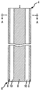
[0024] FIG. 1 is an elevational view of the present invention, according to a
first
embodiment, including a splittable/peelable body for a catheter or sheath,
wherein the body
includes a distal end and a proximal end and is formed of at least two
integral longitudinal
strips of different material.
[0025] FIG. 2A is a latitudinal cross-sectional view of the first embodiment
of the
body taken through section line A-A in FIG. 1.
[0026] FIG. 2B is a longitudinal cross-sectional view of the first embodiment
of the
tubular body taken through section line A'-A' in FIG. 2A.
CA 02604715 2007-10-11
WO 2006/116720 PCT/US2006/016373
[0027] FIG. 3 is an elevational view of the present invention according to a
second
embodiment including a splittable tubular body for a catheter or sheath,
wherein the
tubular body includes a distal end and a proximal end and is formed of at
least two integral
longitudinal strips of different material.
[0028] FIG. 4A is a latitudinal cross-sectional view of the second embodiment
of the
tubular body taken through section line B-B in FIG. 3.
[0029] FIG. 4B is a longitudinal cross-sectional view of the second embodiment
of the
tubular body taken through section line B'-B' in FIG. 4A.
[0030] FIG. 4C is a latitudinal cross-sectional view of a first variation of
the second
embodiment of the tubular body taken through section line B-B in FIG. 3.
[0031] FIG. 4D is a longitudinal cross-sectional view of the first variation
of the
second embodiment of the tubular body taken through section line B"-B" in FIG.
4C.
[0032] FIG. 4E is a latitudinal cross-sectional view of a second variation of
the second
embodiment of the tubular body taken through section line B-B in FIG. 3.
[0033] FIG. 4F is a longitudinal cross-sectional view of the second variation
of the
second embodiment of the tubular body taken through section line B"'-B"' in
FIG. 4E.
[0034] FIG. 5 is an elevational view of the present invention according to a
third
embodiment including a splittable tubular body for a catheter or sheath,
wherein the
tubular body includes a distal end and a proximal end and is formed of at
least two integral
longitudinal helical strips of different material.
[0035] FIG. 6A is a latitudinal cross-sectional view of the third embodiment
of the
tubular body taken through section line C-C in FIG. 5.
[0036] FIG. 6B is a longitudinal cross-sectional view of the third embodiment
of the
tubular body taken through section line C'-C' in FIG. 6A.
[0037] FIG. 7 is an elevational view of the present invention according to a
fourth
embodiment including a splittable tubular body for a catheter or sheath,
wherein the
tubular body includes a distal end and a proximal end and is formed of at
least two integral
longitudinal helical strips of different material.
[0038] FIG. 8A is a cross-sectional view of the fourth embodiment of the
tubular body
taken through section line D-D in FIG. 7.
[0039] FIG. 8B is a longitudinal cross-sectional view of the fourth embodiment
of the
tubular body taken through section line D'-D' in FIG. 8A.
CA 02604715 2007-10-11
WO 2006/116720 PCT/US2006/016373
6
[0040] FIG. 8C is a latitudinal cross-sectional view of a first variation of
the fourth
embodiment of the tubular body taken through section line D-D in FIG. 7.
(0041] FIG. 8D is a longitudinal cross-sectional view of the first variation
of the fourth
embodiment of the tubular body taken through section line D"-D" in FIG. 8C.
(0042] FIG. 8E is a latitudinal cross-sectional view of a second variation of
the fourth
embodiment of the tubular body taken through section line D-D in FIG. 7.
[0043] FIG. 8F is a longitudinal cross-sectional view of the second variation
of the
fourth embodiment of the tubular body taken through section line D"'-D"' in
FIG. 8E.
[0044] FIG. 9 is similar to Fig. 2A, but is a cross-sectional view of the
present
invention according to a fifth embodiment, including a splittable tubular
body, wherein the
tubular body has integral peel grooves that can be located in either the first
or the second
longitudinal strips.
[0045] FIG. 10 is a cross-sectional view of a sixth embodiment of the
splittable body,
including a triangular cross-section.
[0046] FIG. 11 is a cross-section view of a seventh embodiment of the
splittable body,
including a square cross-section.
DETAILED DESCRIPTION OF THE INVENTION
[0047] FIG. 1 is an elevational view of the present invention according to a
first
embodiment including a splittable (i.e., peel-away type) body 2 for a catheter
or sheath.
The body 2 includes a distal end 4 and a proximal end 6. As shown in FIG. 1,
the body 2
is formed of at least two integral longitudinal strips 8, 10 of different
materials. As
indicated in FIG. 1, each strip 8, 10 may extend the full length of the
tubular body 2 in a
generally straight manner. As shown in FIG. 2a, the body can have a tubular
cross section.
As shown in FIGS. 10 and 11, the body can have a triangular 210 or square 220
cross-section.
[0048] The strips 8, 10 will be referred to herein as the first strip 8 and
the second strip
10. The material of the first strip 8 will be sufficiently different from the
material of the
second strip 10 so as to form a stress concentration along the interfacial
zones (i.e.,
borders) 11 between the two strips 8, 10. The stress concentration forms a
peel line 11 that
acts like a built-in peel groove. As a result, the tubular body 2 is readily
splittable although
it lacks an actual peel groove.
CA 02604715 2007-10-11
WO 2006/116720 PCT/US2006/016373
7
[0049] The dissimilarity between the materials used to form the strips 8, 10
need only
be sufficient enough to create a stress concentration that acts as a built-in
peel groove.
This may be accomplished in different ways, including the following ways.
[0050] The materials used for the strips 8, 10 may be generally the same, but
can also
differ. For example, the first strip 8 may be constructed from a first polymer
and the
second strip 10 may be constructed from a second polymer. The polymer used for
the first
strip 8 may have a different molecular orientation than the polymer used for
the second
strip 10. In one embodiment, the material used for the first strip 8 is a
polymer with
flow-induced axial molecular orientation, and the material used for the second
strip 10 is a
polymer having little or no flow-induced axial molecular orientation. In such
an
embodiment, the tear strength along the flow-induced orientation direction for
the
polymeric material used for the first strip 8 will decrease due to the
mechanical anisotropy
induced by the molecular chain alignment. Conversely, due to its low level of
mechanical
anisotropy, the polymeric material used for the second strip 10 will have any
one or all of
the following attributes: high tear strength; high mechanical strength, high
torquability;
and high kink resistance. Examples of materials that can be used for the first
strip 8 and
are easily molecularly oriented along the flow direction during polymer
processing include,
among other materials, crystal polymers like Ticona VectraTM, LKX 1107, and
LKX 1113.
[0051] The base polymer materials used for the first and second strips 8, 10
can be
chemically the same or similar, except, the material used for the first strip
8 can be loaded
with semi-compatible or incompatible inorganic fillers. Such fillers can
include
radiopaque fillers or other general-purpose fillers like silica, clay,
graphite, mica, and
calcium carbonate. The tear strengths and the elongations at yield and break
for the
material used for the first strip 8 will decrease with the increase of the
filler loading.
[0052] The base polymeric materials used for the first and second strips 8, 10
can be
chemically in-compatible. If so, a polymer compatibilizer is introduced to at
least one of
the polymer materials used for the first and second strips 8, 10 to improve
the melt
adhesion between the first and second strips 8, 10.
[0053] After the tubular body 2 is manufactured, the material used for the
first strips 8
can be different from the material used for the second strip 10 with respect
to molecular
orientation and/or anisotropy in mechanical properties. This will especially
be the case
with respect to tear strength and elongation at yield and break. Furthermore,
the materials
CA 02604715 2007-10-11
WO 2006/116720 PCT/US2006/016373
8
used for the first and second strips 8, 10 will be at least partially
compatible such that
self-adhesion interfacial zones 11 are reliably formable between the strips 8,
10.
[0054] The materials used for the strips 8, 10 can be functionally miscible.
To be
functionally miscible, the two materials used for the strips 8, 10, must have
sufficient
adhesion to function for the intended use of the instrument, but must have
sufficient stress
concentrations formed at the interfacial zones 11 between the strips 8, 10 to
readily act as a
built-in peel groove when the instrument has completed its intended function.
In another
embodiment, the materials used for the strips 8, 10 are chemically miscible or
partially
miscible in order to impose the self-adhesion of the strips 8, 10 and create
reliable
interfacial regions 11 between said strips 8, 10. In one embodiment, the
materials used for
the strips 8, 10 include melt-processable thermoplastics (e.g., polyethylene,
polyvinylidene
fluoride, fluorinated ethylene-propylene copolymer, Polyethylene-co-
tetrafluoroethylene,
plypropylene, polyamide-6, polyamide-6.6, polyamide-11, polyamide-12,
polyethylene
terephathlate, polybutylenes terephathlate, polycarbonates, polystyrene, etc.)
and
thermoplastic elastomers ("TPEs") (e.g., polyamide-based TPEs, olefinic TPEs,
ionic
TPEs, polyester-based TPEs, thermoplastic polyurethanes, etc.).
[0055] The material used for the first strip 8 can be a material highly loaded
with a
radiopaque material. In such an embodiment, the first strip 8 is referred to
as the high
radiopacity strip(s) 8. In the same embodiment, the material used for the
second strip 10 is
a material that is not loaded or a material that is lightly loaded with a
radiopaque material.
In such an embodiment, the second strip 10 is referred to as the low
radiopacity strip(s) 10.
[0056] As will described in greater detail later in this Detailed Description,
the tubular
body 2 is inserted into the body of a patient via a surgical site (e.g.,
entering the chest
cavity below the xiphoid process) and directed to a point of treatment (e.g.,
the pericardial
space of a heart). Alternatively, the tubular body 2 is inserted into the body
of a patient via
a body lumen of a patient (e.g., a blood vessel) and manipulated so it travels
along the
body lumen to a point of treatment (e.g., a chamber in the heart). A medical
device is
implanted at the point of treatment via the tubular body 2. To allow the
removal of the
tubular body 2 without disturbing the implanted medical device (e.g.,
pacemaker leads),
the tubular body 2 is longitudinally split along the interfaces 11 between the
strips 8, 10 by
simply forcing the sides of the tubular body 2 apart via a fingernail, tool or
other
implement. The stress concentrations 11 formed at the interfaces 11 between
the strips 8,
CA 02604715 2007-10-11
WO 2006/116720 PCT/US2006/016373
9
act as a built-in peel groove. The split tubular body 2 is then removed from
about the
implanted medical device.
[0057] Where the tubular body 2 includes a first strip 8 formed from a
material that is
highly-loaded with a radiopaque material (i.e., the first strip 8 is a high
radiopacity strip 8),
the travel and positioning of the tubular body 2 within the patient may be
monitored via
X-ray fluoroscopy.
[0058] As will become evident from this Detailed Description, the splittable
tubular
body 2 in its various embodiments provides the following advantages. First,
the tubular
body 2 is readily splittable between the two types of strips 8, 10 without the
presence of a
peeling groove, score or skive. Second, the tubular body 2 is less expensive
to
manufacture than prior art splittable tubular bodies because a peel groove
does not need to
be formed on the tubular body 2, and the tubular body 2 can be made in a
single simple
process, such as co-extrusion, co-injection molding, or co-compression
molding.
[0059] In embodiments of the tubular body 2 that have first strips 8 made of
materials
that are highly-loaded with radiopaque materials (i.e., tubular bodies 2 with
high
radiopacity strips 8), such tubular bodies 2 will also have the following
advantages. First,
because the tubular body 2 is visible in the human body along its entire
length via an X-ray
fluoroscope, a physician does not need to estimate the position of the extreme
end of the
distal tip 4 as is required with prior art tubular bodies that have radiopaque
rings implanted
in their distal ends. Second, because the tubular body 2 is made from
compatible polymers
or polymeric compounds without the use of pure metals or metallic compounds,
the tubular
body 2 has better material compatibility and mechanical integrity than prior
art tubular
bodies. Third, by having a tubular body 2 with both high radiopacity strips 8
and low
radiopacity strips 10, the tubular body is highly flexible, yet highly kink
resistant. Other
advantageous aspects of the tubular body 2 will become apparent throughout
this Detailed
Description.
[0060] For a better understanding of the first embodiment of the tubular body
2 and its
strips 8, 10, reference is now made to FIGS. 2A and 2B. FIG. 2A is a cross-
sectional view
of the first embodiment of the tubular body 2 taken through section line A-A
in FIG. 1.
FIG. 2B is a longitudinal cross-sectional view of the first embodiment of the
tubular body
2 taken through section line A'-A' in FIG. 2A. As shown in FIGS. 2A and 2B,
the first
embodiment of the tubular body 2 includes a wall 12 that has an outer
circumferential
surface 14 and an inner circumferential surface 16. The outer circumferential
surface 14
CA 02604715 2007-10-11
WO 2006/116720 PCT/US2006/016373
forms the outer surface of the tubular body 2 and the inner circumferential
surface 16
defines a lumen 18 through the tubular body 2 that runs the full length of the
tubular body
2.
[0061] As illustrated in FIG. 2A, each strip 8, 10 forms an integral segment
of the wall
12. As shown in FIG. 2A, the tubular body 2, in one embodiment, may have four
first
strips 8 and four second strips 10 that are formed together (e.g. under a co-
extrusion
process) to create a wall 12 that is circumferentially continuous and integral
along its entire
length. In other embodiments, there will be as few as one first strip 8 and
one second strip
10. In yet other embodiments, there will be any number of each type of strip
8, 10,
including more than four first strips 8 and four second strips 10. Also, in
some
embodiments, one type of strip 8, 10 will outnumber the other type of strip 8,
10.
[0062] In one embodiment with two first strips 8 and two second strips 10,
each strip
8, 10 will have a width that comprises approximately 25% of the circumference
of the
tubular body wall 12. In other embodiments where the strips 8, 10 each account
for
generally equal percentages of the circumference of the tubular body wall 12,
the width of
the strips 8, 10, depending on the total number of strips, will range between
approximately
2% and approximately 50% of the circumference of the tubular body wall 12.
[0063] In one embodiment, one type of strip 8, 10 may constitute a greater
percentage
of the circumference of the tubular body wall 12. In other words, the first
strips 8 may
have greater widths than the second strips 10, or vice versa. For example, as
illustrated in
FIG. 2A, each of the four first strips 8 account for approximately 17% of the
circumference
of the tubular body wall 12, while each of the second strips 10 each account
for
approximately 8% of the circumference of the tubular body wall 12. Similarly,
in another
embodiment with two first strips 8 and two second strips 10, each of the two
second strips
10 accounts for approximately 33% of the circumference of the tubular body
wall 12,
while each of the two first strips 8 accounts for approximately 17% of the
circumference of
the tubular body wall 12. Again, depending on the number of strips 8, 10, in
other
embodiments, the width of the strips 8, 10 may range between approximately 2%
and
approximately 50% of the circumference of the tubular body wall 12. In other
embodiments, the width of one or more of the strips 8, 10 will be between
approximately
0.1% and approximately 5% to form a micro strip 8, 10.
[0064] In one embodiment, one or more of the strips 8, 10 may have a unique
percentage of the circumference of the tubular body wall 12. For example, in
an
CA 02604715 2007-10-11
WO 2006/116720 PCT/US2006/016373
11
embodiment of the tubular body 2 having multiple first strips 8, at least one
(if not all) of
the first strips 8 has a unique width. Thus, in one embodiment, the widths 8
of the first
strips are not all equal. In other embodiments, a similar configuration could
exist for at
least one (if not all) of the second strips 10 or at least one (if not all) of
the strips 8, 10.
[0065] In one embodiment, the lumen 18 will have a diameter of between
approximately 4 French ("F") and approximately 22 F. In one embodiment, the
tubular
body 2 will have an outer diameter of between approximately 5 F and
approximately 24 F.
In one embodiment, the tubular body 2 will have a wall with a thickness of
between
approximately .006" and approximately 0.026".
[0066] For a discussion of a second embodiment of the invention, reference is
now
made to FIGS. 3, 4A and 4B. FIG. 3 is an elevational view of a second
embodiment of the
radiopaque tubular body 2 having a distal end 4 and a proximal end 6 and being
formed of
at least two integral longitudinal strips 8, 10. These strips 8, 10 can have
different
radiopacities. FIG. 4A is a latitudinal cross-sectional view of the second
embodiment of
the tubular body 2 taken through section line B-B in FIG. 3. FIG. 4B is a
longitudinal
cross-sectional view of the second embodiment of the tubular body 2 taken
through section
line B'-B' in FIG. 4A.
[0067] As can be understood from FIG. 3 and as is more readily seen in FIGS.
4A and
4B, the second embodiment of the tubular body 2 and its strips 8, 10 are
configured
similarly to those in the first embodiment of the tubular body 2 as depicted
in FIGS. 1, 2A
and 2B, except the first strips 8 of the second embodiment are subjacent to
layers of second
strip material 10', 10" that form the outer and inner circumferential surfaces
14, 16 of the
tubular body wall 12. In other words, as illustrated in FIGS. 3, 4A and 4B,
the first strips 8
of the second embodiment of the tubular body 2 are sandwiched between an outer
layer 10'
and an inner layer 10" of second strip material 10.
[0068] In other variations of the second embodiment, the first strips 8 of the
second
embodiment of the tubular body 2 are subjacent to a single layer of second
strip material
10. For example, in a first variation of the second embodiment of the tubular
body 2, as
depicted in FIGS. 4C and 4D, which are, respectively, a latitudinal cross-
sectional view of
the tubular body 2 taken through section line B-B in FIG. 3 and a longitudinal
cross-
sectional view of the tubular body 2 taken through section line B"-B" in FIG.
4C, the first
strips 8 are subjacent to a single layer of second strip material 10, which is
an outer layer
10'. Thus, as depicted in FIGS. 4C and 4D, the second strip outer layer 10'
forms the outer
CA 02604715 2007-10-11
WO 2006/116720 PCT/US2006/016373
12
circumferential surfaces 14 of the tubular body wall 12 and the first strips 8
form segments
of the inner circumferential surface 16 of the tubular body wall 12.
[0069] Similarly, in a second variation of the second embodiment of the
tubular body
2, as depicted in FIGS. 4E and 4F, which are, respectively, a latitudinal
cross-sectional
view of the tubular body 2 taken through section line B-B in FIG. 3 and a
longitudinal
cross-sectional view of the tubular body 2 taken through section line B"'-B"'
in FIG. 4E,
the first strips 8 are subjacent to a single layer of second strip material
10, which is an
inner layer 10". Thus, as depicted in FIGS. 4E and 4F, the second strip inner
layer 10"
forms the inner circumferential surfaces 16 of the tubular body wall 12 and
the first strips 8
form segments of the outer circumferential surface 14 of the tubular body wall
12.
[0070] For a discussion of a third embodiment of the invention, reference is
now made
to FIGS. 5, 6A and 6B. FIG. 5 is an elevational view of a third embodiment of
the tubular
body 2 having a distal end 4 and a proximal end 6 and being formed of at least
two integral
longitudinal helical strips 8, 10. these strips 8, 10 can have different
radiopacities. FIG.
6A is a latitudinal cross-sectional view of the third embodiment of the
tubular body 2 taken
through section line C-C in FIG. 5. FIG. 6B is a longitudinal cross-sectional
view of the
third embodiment of the tubular body 2 taken through section line C'-C' in
FIG. 6A.
[0071] As shown in FIGS. 5, 6A and 6B, in the third embodiment of the tubular
body
2, its strips 8, 10 are configured similarly to those in the first embodiment
of the tubular
body 2 as depicted in FIGS. 1, 2A and 2B, except the strips 8, 10 of the
second
embodiment extend spirally or helically along the length of the third
embodiment of the
tubular body 2.
[0072] For a discussion of a fourth embodiment of the invention, reference is
now
made to FIGS. 7, 8A and 8B. FIG. 7 is an elevational view of a fourth
embodiment of the
tubular body 2 having a distal end 4 and a proximal end 6 and being formed of
at least two
integral longitudinal helical strips 8, 10. These strips 8, 10 can have
different radiopacities.
FIG. 8 is a latitudinal cross-sectional view of the fourth embodiment of the
tubular body 2
taken through section line D-D in FIG. 7. FIG. 8B is a longitudinal cross-
sectional view of
the fourth embodiment of the tubular body 2 taken through section line D'-D'
in FIG. 8A.
[0073] As can be understood from FIG. 7 and as is more readily seen in FIGS.
8A and
8B, the fourth embodiment of the tubular body 2 and its helical strips 8, 10
are configured
similarly to those in the third embodiment of the tubular body 2 as depicted
in FIGS. 5, 6A
and 6B, except the helical first strips 8 of the fourth embodiment are
subjacent to layers of
CA 02604715 2007-10-11
WO 2006/116720 PCT/US2006/016373
13
second strip material 10', 10" that form the outer and inner circumferential
surfaces of the
tubular body wall 12. In other words, as illustrated in FIGS. 7, 8A and 8B,
the helical first
strips 8 of the fourth embodiment of the tubular body 2 are sandwiched between
an outer
layer 10' and inner layer 10" of second strip material 10.
[0074] In other variations of the fourth embodiment, the first strips 8 of the
fourth
embodiment of the tubular body 2 are subjacent to a single layer of second
strip material
10. For example, in a first variation of the fourth embodiment of the tubular
body 2, as
depicted in FIGS. 8C and 8D, which are, respectively, a latitudinal cross-
sectional view of
the tubular body 2 taken through section line D-D in FIG. 7 and a longitudinal
cross-sectional view of the tubular body 2 taken through section line D"-D" in
FIG. 8C, the
first strips 8 are subjacent to a single layer of second strip material 10,
which is an inner
layer 10". Thus, as depicted in FIGS. 8C and 8D, the second strip inner layer
10" forms
the inner circumferential surface 16 of the tubular body wall 12 and the first
strips 8 form
segments of the outer circumferential surface 14 of the tubular body wall 12.
[0075] Similarly, in a second variation of the fourth embodiment of the
tubular body
2, as depicted in FIGS. 8E and 8F, which are, respectively, a latitudinal
cross-sectional
view of the tubular body 2 taken through section line D-D in FIG. 7 and a
longitudinal
cross-sectional view of the tubular body 2 taken through section line D"'-D"'
in FIG. 8E,
the first strips 8 are subjacent to a single layer of second strip material
10, which is an
outer layer 10'. Thus, as depicted in FIGS. 8E and 8F, the second strip outer
layer 10'
forms the outer circumferential surface 14 of the tubular body wall 12 and the
first strips 8
form segments of the inner circumferential surface 16 of the tubular body wall
12.
[0076] The first strips 8 and the second strips 10 can be formed from two
compatible
polymers or polymeric compounds into an integral tubular body 2 via co-
extrusion, co-
injection molding, or co-compression molding processes. Candidate polymeric
materials
include thermoplastic and thermosetting polymer systems.
[0077] The first strips 8 may be formed of material that is heavily filled
with a
biocompatible filler of heavy metal or a biocompatible metallic compound that
gives rise
to high radiopacity under X-ray radiation. The functional width and wall
thickness (i.e.,
percentage of the circumference of the tubular body wall 12) necessary for
visibility via
X-ray fluoroscopy will vary depending on the degree of radiopacity for a first
strip 8 (i.e.,
high radiopacity strip 8). For example, where a first strip 8 has a high
degree of
radiopacity (due to the radiopaque nature of the filler of metal or metallic
compound
CA 02604715 2007-10-11
WO 2006/116720 PCT/US2006/016373
14
impregnated in the polymer and/or due to the percentage of the metal or
metallic
compound in the polymer), narrower and thinner first strips 8 will suffice. On
the other
hand, where a first strip 8 has a lower degree of radiopacity, wider and
thicker first strips 8
will be required to achieve the necessary visibility via X-ray fluoroscopy.
[0078] The first strips 8 (i.e., high radiopacity strips 8), if they are made
from
elastomeric polymer materials loaded with radiopaque fillers, provide kink
resistance for
the tubular body 2 in addition to providing the ability to be visualized
within a patient's
body via X-ray fluoroscopy. In a preferred embodiment, the first strips 8 will
be a
tungsten-impregnated thermoplastic elastomer, including thermoplastic
polyurethane,
polyether block amide, and etc. The amount of tungsten used will depend on the
degree of
radiopacity required and the thermoplastic elastomer. For example, when the
strips are
formed of PEBAX, the first strip can be loaded with 60-95% by weight tungsten,
and
preferably 80-85% by weight tungsten.
[0079] The second strips 10 (i.e., low radiopacity strips 10) are either not
loaded with
radiopaque fillers or are lightly loaded. Thus, the second strips 10 have a
low radiopacity
under X-ray radiation and provide mechanical strength and durability for the
tubular body
2.
[0080] For melt processing purposes, the selection of the pairs of polymers
used for
the strips 8, 10 is primarily based on the level of chemical compatibility,
balance of
mechanical properties, and melt processability between the pairs of polymers.
Different
grades of polymers having the same constituent chemical species (e.g., various
thermoplastic elastomers, including polyether block amides, polyurethanes,
olefinics,
styrenics, polyesters, polyethers, and etc.) may be used for the pairs. Pairs
of
thermoplastics and thermoplastic elastomers can also be used (e.g., polyamides
with
polyether block amides, polyesters with polyether-co-esters). Other polymer
pairs are
possible with use of polymer compatibilization technologies.
[0081] For radiopaque tubular bodies 2, one base polymer from a polymer pair
must
be filled with heavy metals or metallic compounds using blending and
compounding
technologies via either melt or solvent processes. The heavy metals and
compounds shall
be biocompatible (e.g., barium, tungsten, tantalum, platinum, gold, bismuth,
zirconium,
niobium, titanium, bismuth oxychloride, barium sulfate, bismuth trioxide,
iodine, iodide,
etc. and their compounds). In one embodiment, the biocompatible radiopaque
filler will
contain at least one element with an atomic number of from about 22 to about
83.
CA 02604715 2007-10-11
WO 2006/116720 PCT/US2006/016373
[0082] Filler of a heavy metal or a metallic compound may not be compatible
with a
selected base polymer, and may cause a drastic decrease in mechanical
properties in the
heavily loaded polymer compound. To increase the loading level of radiopaque
filler and
to improve the compatibility of the filler with the base polymer, a
compatibilizer or
coupling agent can be used for the polymer compound.
[0083] As previously noted, the tubular bodies 2 are peelable (i.e.,
splittable) at one or
more border(s) (i.e., interface(s)) between the two types of strips 8, 10. To
longitudinally
split the tubular body 2, opposite sides of the interior circumferential
surface 16 are simply
forced apart via a fingernail, tool or other implement. The change in material
at the
borders between the strips 8, 10 creates a stress concentration point that
acts as a built in
peel groove along which the tubular body 2 splits when peeled. Thus, no
integral peeling
groove is needed. However, in some embodiments, as indicated in FIG 9, an
integral peel
groove, skive or score 20 is provided to supplement the peelability of the
tubular body 2.
This can be readily implemented in the embodiments illustrated in FIGS. 1-4.
Ideally, this
peel groove, skive or score 20 is aligned longitudinally with a boarder
between a pair of
strips 8, 10. However, the peel groove, skive or score 20 can be located in
one of the strips
8, 10 as indicated in FIG. 9. A tubular body 2 can have one or more peel
grooves, skives
or scores. The peel groove, score or skive 20 can be located in the inner
and/or outer
circumferential surface of the tubular body 2.
[0084] Many of the aforementioned embodiments employ at least one strip 8, 10
formed of a material loaded with a radiopaque material. However, the strips 8,
10 can be
formed of polymers that are not loaded with a radiopaque or other materials.
For example,
the first strips 8 can be formed from a polymer that is dissimilar from the
polymer forming
the second strips 10. The dissimilarity between the two polymers forming the
two strips 8,
10 results in a stress concentration along the interfacial boundary between
the two strips 8,
10. The stress concentration serves as a split/peel feature in the tubular
body 2 for
splitting/peeling the body 2.
[0085] The polymers of the strips 8, 10 can be the same polymer, but
dissimilar
because they have dissimilar molecular orientations. The polymers of the
strips 8, 10 can
be the same polymer, but dissimilar because they have different toughness,
hardness,
rigidity, and/or etc. For example, the first or splitting strip 8 can be
formed of PEBAX
having a durometer value of approximately 70D, and the second or non-splitting
strip 10 is
formed of PEBAX having a durometer value of approximately 30-40D.
CA 02604715 2007-10-11
WO 2006/116720 PCT/US2006/016373
16
[0086] In use, a puncture is made with a thin walled needle through the skin
and into a
blood vessel. A guidewire is then placed through the needle into the blood
vessel and the
needle is withdrawn. An intravascular introducer is advanced over the
guidewire into the
lumen of the blood vessel. The tubular body 2 is inserted into the introducer
and
manipulated so it travels along the blood vessel to the point of treatment
(e.g., a chamber in
the heart). The travel and positioning of the tubular body 2 within the
patient is monitored
via X-ray fluoroscopy.
[0087] In use, the tubular body 2 is inserted into the body of a patient via a
surgical
site (e.g., entering the chest cavity below the xiphoid process). A guidewire
is used to
direct the tubular body 2 to a point of treatment (e.g., the pericardial space
of a heart). The
travel and positioning of the tubular body 2 within the patient is monitored
via X-ray
fluoroscopy.
[0088] Although the present invention has been described with reference to
preferred
embodiments, persons skilled in the art will recognize that changes may be
made in form
and detail without departing from the spirit and scope of the invention.