Note: Descriptions are shown in the official language in which they were submitted.
CA 02604718 2011-04-05
WO 2006/110716 PCT/US2006/013432
FOLDING HINGE
FIELD OF THE INVENTION
Embodiments of the invention relate to camera support equipment, and
more particularly to hinges connecting components thereof.
BACKGROUND OF THE INVENTION
is
FIG. I depicts a conventional basic body mounted or hand held camera
support and stabilization system 100. It includes a top stage 102 for camera
mounting,
post 104 and gimbal mechanism 106 for support of a camera and stabilizer
system about
a common pivot point, a monitor 108 for viewing the camera's image, and a
lower
support (sled) 110 that interconnects the post, a battery system 112, and
miscellaneous
electronic systems. Battery power must be supplied to the camera, and the
viewer must be
functionally connected to the camera, so the image captured by the camera can
be seen.
As is apparent from FIG. 1, the camera is displaced from the viewer and the
battery, and
therefore, wires or cables must extend between the camera and these auxiliary
components. (The term "cable" as used herein will include any flexible
component that
can functionally link cameras to auxiliary components such as viewers and
batteries.)
Typically, to accomplish this connect coaxial cable and stranded copper cables
are run
through connectors, or via hard wiring, from the lower sled portion 110, up
through the
post 104, to the top stage 102. Within the top stage section, power and video
cables are
then typically broken out to external connectors and then connected to the
camera. Within
this structure the preferred method of running the cables to the top stage
section is within
the post itself. Doing this helps to protect the cables from damage and also
allows for
unimpeded operation of the camera stabilization system without concern for
having the
1
CA 02604718 2007-10-10
WO 2006/110716 PCT/US2006/013432
operator or other equipment being entangled in the cables. The common approach
in
connecting the post cables to the lower sled portion 110 is either via a hard
wired
connection through a rigidly attached post or via an interconnect connector
attached to a
removable post. If a hard wired/rigid post method is employed, the camera
stabilization
type system is limited as to how compact it can become for storage and
transport. When
employing the removable post method, the cost of the assembly is increased
because of
the addition of connectors, and reliability of electrical or optical
connections between
post and sled is decreased.
Compacting of the camera stabilization system is desired in order to
reduce the volumetric space required for storage and transport. Decreasing
this size as
much as possible allows users of the system to transport the device at a lower
cost, and to
have it fit more readily in compact spaces such as in cars. In effect, the
system is made
more portable. In having the ability to compact the system, the durability and
reliability
of the camera stabilization device must be maintained.
Currently there are a number of schemes to connect the post mechanism to
the main lower sled body. They include, for example, mechanically rigid, non-
removable
or separable post mechanisms with hard wired electrical/fiber optic
connections disposed
internally within the post and sled. Also used are mechanically removable post
mechanisms with connectorized electrical/fiber optic connectors internal to
the post and
sled. Another mechanically rigid, non-removable or separable post mechanism
has hard
wired electrical/fiber optic connections external to the post and sled. An
external
mechanism may also incorporate connectorized electrical/fiber optic
connectors.
SUMMARY OF THE INVENTION
Embodiments of the invention provide a folding hinge for camera
stabilization equipment. The hinge includes support connectors having
apertures through
which cables may be passed to connect a camera with various auxiliary
components. An
indexing guide pivotally attaches the support connectors so the camera
stabilization
system can be folded and unfolded with little or no disruption of the cables
or system
balance. Locking mechanisms secure the hinges to provide a desired angular
relationship
between support members connected by the hinge.
2
CA 02604718 2007-10-10
WO 2006/110716 PCT/US2006/013432
The invention further includes camera support systems using embodiments
of the folding hinge and a method for of connecting camera equipment in such
support
systems.
DESCRIPTION OF THE DRAWINGS
The invention is best understood from the following detailed description
when read with the accompanying drawings.
Figure 1 depicts a prior art camera stabilizing system in which illustrative
1o embodiments of the invention can be used.
Figures 2A-E depict a folding hinge mechanism in various positions
according to an illustrative embodiment of the invention.
Figure 3A-B show a folding hinge having an indexed stop position
according to an illustrative embodiment of the invention.
Figure 4 depicts a support member slidably attached to a folding hinge
according to an illustrative embodiment of the invention.
Figures 5A-B depict use of a folding hinge to balance equipment on a
stabilizing system according to an illustrative embodiment of the invention.
FIG. 6 depicts an illustrative example of a folding hinge mechanism
mounted on a lower sled.
DETAILED DESCRIPTION OF THE INVENTION
In addition to allowing increased portability and reliability, the
implementation of a hinged post mechanism may also improve the ability to
achieve
balance in the camera stabilization system. By introducing a common pivot
point to the
sled/post interface junction, and introducing a horizontally positionable
monitor and
battery support member, the major counterbalance components (battery and
monitor) can
be readily positioned to help achieve system balance.
Advantageously, embodiments of the inventive folding post hinge
mechanism may provide greater electrical connection reliability due to the
elimination of
2+ solder type electrical connections per wire in comparison to the removable
post
method. Connection reliability for optical fiber type connections may also be
improved
3
CA 02604718 2007-10-10
WO 2006/110716 PCT/US2006/013432
in comparison to the removable post method due to elimination of interconnect
connectors. A rigid connection mechanism eliminates or reduces the possibility
of
cable/wire damage due to twist or abrasion as would happen for non-
mechanically
restrained post/sled interconnects. The ability to conceal and protect the
cable path from
post to sled body has thus far not been accomplished with the conventional
technology.
Additionally, contact impedance may be reduced or eliminated, in
comparison to the removable post method. Furthermore, the possibility of
contact
damage or contact damage through misalignment, or exposure to foreign matter
or
moisture may be reduced or eliminated in comparison to the removable post
method.
Cost may also be reduced for certain embodiments of the invention due to
the elimination of fiber optic and/or electrical connectors in comparison to
the removable
post method. Cost reductions may also be generated because there will be a
reduction in
labor that is required to construct the interconnect assembly in comparison to
the
removable post method.
Embodiments of the invention allow the post mechanism to fold easily for
compact storage and transport in comparison to the fixed post method.
Approximately
31% in space savings have been achieved using particular configurations of the
invention. Compacting of the sled mechanism can be convenient and, in
exemplary
embodiments, performed without the use of tools.
A variation on the configuration will allow another way to balance the
camera stabilization system by rigidly locking the post/sled interconnection
point at
various angles, and having the monitor and battery, or other equipment,
counter balance
weights balance about that common point.
Embodiments of the folding hinge can be placed at various intersections of
components of a camera stabilizing system to provide a protected avenue
through which
cables can be passed through and further to allow the equipment to be folded
or
compacted without having to entirely disassemble the system.
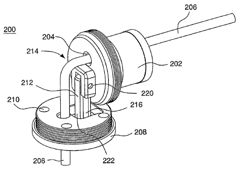
FIGS. 2A-E depicts a folding hinge mechanism 200 according to an
illustrative embodiment of the invention. A first support connector 202,
having one or
more apertures 204 therethrough is provided. Cable 206 is positioned to extend
through
aperture 204. A second support connector 208 is positioned so cable 206 can
extend
4
CA 02604718 2007-10-10
WO 2006/110716 PCT/US2006/013432
through it aperture(s) 210. An indexing guide 212 is positioned between first
support
connector 202 and second support connector 208. Indexing guide 212 has a first
end 214
connected to first support connector 202 and a second end 216 connected to
second
support connector 208. Indexing guide 212 pivotally connects first support
connector
202 to second support connector 208. Illustrative indexing guide 212 has two
slotted
sections 220 and 222 that allow first and second support connectors 202 and
208 to pivot
with respect to each other and to slide apart from one another without totally
separating.
Slotted section 222 can slide into first support connector 202. Various
pivoting
mechanisms can be used provided they are compatible with the support
connectors and
allow one or more cables to pass through support connectors 202, 208. Indexing
guide
212 may maintain a twist free, restrained movement of the mechanism to help
prevent
cable or harness damage.
A locking collar 218 is releasably attached to first support connector 202
and second support connector 208 and alignable with the support connectors to
allow the
one or more flexible components to pass through locking collar 218. Locking
collar 218
can be secured to first and second support connectors 202, 208 by, for
example, threaded
surface on both locking collar 218 and support connectors 202, 208. Locking
collar 218
may also snap into place, for example by a detent mechanism. Use of a locking
collar
may dampen vibrations and movement typically occurring at such joints. In the
embodiments depicted in FIGS. 2A-E, indexing guide 212 is disposed within
locking
collar 218 when the locking collar is attached to both the first support
connector 202 and
the second support connector 208. FIG. 2D depicts folding hinge 200 in a
linear position
without locking collar 218. FIG. 2E depicts folding hinge 200 in a linear
position with
locking collar 218 in place to keep hinge 200 from opening, i.e. pivoting/
The embodiments shown in FIG. 2A-E provide a linear support once the
hinge is locked in place. It is sometimes desirable to maintain two support
members at an
angle with respect to one another. FIGS. 3A-B depict illustrative embodiments
of a
folding hinge 300 having an index locking mechanism to lock an index guide 302
in
position with respect to a first support connector 304 and a second support
connector 306.
Folding hinge 300 has two or more indexed stop positions created by various
openings in
the locking components. FIGS. 3A-B show a first pivot locking component 310
5
CA 02604718 2007-10-10
WO 2006/110716 PCT/US2006/013432
incorporated into indexing guide 302 and having one or more lateral openings
308
therethrough. A second pivot locking component 312 is rigidly attached to one
of the
first or second support connectors 304, 306 and has one or more openings 314
therethrough. At least one of the one or more first pivot locking component
lateral
openings 308 is alignable with at least one of the one or more second pivot
locking
component openings 314. Once aligned, a locking pin or stop component 316 can
be
inserted through a lateral opening 308 and an aligned opening 314, thereby
securing the
index guide in place so support components 304, 306 are at a desirable angle
to one
another.
Embodiments of the invention provide various support members attached
to a folding hinge. The attachment mechanism type between the support member
and the
folding hinge will depend in part on the design of the support member. FIG. 2C
depicts a
collar attachment, which is suitable, for example, to attaching a post to the
hinge. FIGS.
4 and 5A-B depict a flat support member 402 slidably attached to a folding
hinge 400 at a
first support connector 404. (Although support member 402 is referred to as a
"flat
support member", it can be any cross-sectional shape compatible with the
apparatus and
hinge.) A second support connector 406 is attached to a post 408. Flat support
member
402 is inserted through a slot 410. The particular embodiment shown provides a
mechanism to adjust the position of flat support member 402 with respect to
hinge 400.
Flat support member 402 can be locked in place at various longitudinal points.
FIGS. 5A-B depict use of hinge 400 to balance equipment on a stabilizing
system. Viewer or monitor 412 is balanced with respect to battery 414, and
possible
other equipment by sliding flat support member 402 through folding hinge 400.
Folding
hinge 400 can also be secured at a non-perpendicular angle to the horizontal,
as depicted
in FIG. 5A, for balancing and desirable positioning of the equipment. FIG. 5B
shows
another illustrative balancing/positioning configuration.
Other examples of connections that can be made with illustrative
embodiments of folding hinges are between a camera mounting stage and post;
gimbal
and post; monitor mounting platform and support member; and between other
equipment
mounts and posts or support members. Balancing arms, such as seen in Steadicam
equipment can also be connected to stabilizing systems with embodiments of the
folding
6
CA 02604718 2007-10-10
WO 2006/110716 PCT/US2006/013432
hinge. Embodiments of the invention include these various support and mounting
components, and the associated camera equipment. FIG. 6 depicts an
illustrative
example of a folding hinge mechanism 500 mounted on a lower sled portion 502.
Embodiments of the invention also include a method of connecting camera
equipment on a support system using the inventive hinges as described herein.
One or
more hinges are provided to connect components of a stabilizing system. Cables
are run
through the hinge(s) and connected to the desired camera equipment. The
hinge(s) are
positioned at the desired angle, if adjustable in that manner, and secured in
place, but
pins, collars or the like. The stabilizing equipment can then be folded
without affecting
the adjustments and balancing of the system. Upon unfolding the system, the
desired
balancing and adjustments remain unaffected.
A variation on the hinge mechanism use a mechanically hinged
mechanism that maintains electrical contact between the post and sled portions
through a
slip ring or wiper type connection system.
Illustrative embodiments of the invention include a lower portion of a
cable or harness secured in place while an upper portion of the cable is
allowed to pass
freely through an opening in order to allow the hinge mechanism to. operate.
This in turn
allows the cable(s) to move freely and not bind.
Top and bottom support connectors may be indexed together in the X and
Y directions without the need for additional indexing components so as to
maintain the
rigidity required for correct operation and balance of the camera
stabilization system.
While the invention has been described by illustrative embodiments,
additional advantages and modifications will occur to those skilled in the
art. Therefore,
the invention in its broader aspects is not limited to specific details shown
and described
herein. Modifications, for example, to the application of the hinge to other
system-types,
may be made without departing from the spirit and scope of the invention.
Accordingly,
it is intended that the invention not be limited to the specific illustrative
embodiments
described herein, but be interpreted within the full spirit and scope of the
appended
claims and their equivalents.
7