Note: Descriptions are shown in the official language in which they were submitted.
CA 02604891 2012-05-22
RACEWAY WITH MULTI-POSITIONABLE RECEPTACLE BLOCKS
CROSS-REFERENCE TO RELATED APPLICATIONS
BACKGROUND OF THE INVENTION
Field of the Invention
The invention relates to electrical power and communications distribution
systems and, more particularly, to systems having raceway locations which may
be of
differing widths.
Background Art
Known interior wall systems typically employ pre-fabricated modular units.
These units are often joined together in various configurations, so as to
divide a
workplace into smaller offices or work areas. Generally, such modular wall
panels
may be equipped with means for receiving general building power and, possibly,
general communications. Such building power may, for example, be conventional
AC
power received either under floor or from relatively permanent walls or the
like. In
various types of environments comprising electrical equipment, or wherein
electrical
apparatus are otherwise employed, interconnections of electrical components to
incoming utility power are typically provided by means of cables or wires. For
example, in office systems compromising modular furniture components, it is
often
necessary to provide electrical interconnections between incoming power
supplies and
various types of electrical devices typically used in an office environment,
such as
electric typewriters, lamps,
1
CA 02604891 2007-10-05
WO 2007/027243 PCT/US2006/017321
etc. Computer-related devices, such as video display terminals and similar
peripherals, are also
now commonly employed in various office and industrial environments.
One advantage inherent in modular office systems is the capability to
rearrange
furniture components as necessitated by changes in space requirements,
resulting from changes
in the number of personnel and other business-related considerations. However,
these modular
systems must not only allow for change in furniture configurations, but also
must provide for
convenient interconnection of electrical devices to utility power, regardless
of the spacial
configuration of the modular systems and resultant variable distances between
electrical devices.
In providing the interconnection of electrical apparatus and power inputs, it
is
necessary to include an arrangement for feeding the incoming utility power to
the power outlets.
In stationary structures, such as conventional industrial buildings and the
like, a substantial
amount of room would normally exist behind stationary walls and other areas in
which to
provide the requisite cabling for interconnecting incoming utility power to
electrical receptacles
mounted in the walls. Such systems, however, can be designed so as to remain
stationary
throughout their lifetime, without requiring general changes in the office or
industrial
environment areas.
In addition to receiving electrical power from the general incoming building
power supply, modular office systems typically require communications
connections for office
equipment such as telephones, internet communications and the like. The
problems associated
with providing distribution of communications essentially correspond to the
same problems
existing with respect to distribution of conventional electrical power.
In this regard, it is known to provide modular wall panels with areas
characterized
as raceways. Often, these raceways are located along bottom edges of modular
panels. The
2
CA 02604891 2007-10-05
WO 2007/027243 PCT/US2006/017321
raceways are adapted to house electrical cabling and electrical junction
blocks. The cabling and
junction blocks are utilized to provide electrical outlets and electrical
power connections to
adjacent panels. However, it is also apparent that to the extent reference is
made herein to
providing electrical outlets and electrical power connections for adjacent
panels, the same issues
exist with respect to providing communications among panels.
Still further, it is known that the raceway of one modular wall unit may be
provided with a male connector at one end, and a female connector at another
end. Pairs of
junction blocks, each provided with electrical outlets, made to be disposed at
spaced-apart
positions along the raceway. Conduits may be extended between the junction
blocks and
.0 between the connectors in the junction blocks. In this manner, electrical
interconnection is
provided between the units.
The modular panels of a space-divider may be configured, such that adjacent
panels are in a straight line, or at various angular positions relative to
each other. It is common
to configure intersecting walls in such a fashion that three or four modular
wall panels may
intersect at right angles. Each of the panels typically requires electrical
outlets, and may require
outlets on both sides of the panels. In any event, electrical power has to be
provided to all of the
panels, and often only one of the panels at the multiple panel junction is
connected to a power
supply source. Under such circumstances, the interconnecting wiring becomes a
significant
problem. That is, special modifications may have to be made to power systems
of wall panels to
be used in such a configuration. Because interchangeability of wall panels is
highly desirable,
custom modifications are preferably avoided. Still further, modifications of
wall panels on site at
the installation facility is complex and may be relatively expensive.
3
CA 02604891 2007-10-05
WO 2007/027243 PCT/US2006/017321
In addition to the foregoing issues, problems can arise with respect to the
use of
junction blocks and the amount of room which may exist within a raceway. That
is, raceways
require sufficient room so as to provide for junction blocks, electrical
outlet receptacle blocks,
and cabling extending between junction blocks and between adjacent panels.
One example of a prior art system is illustrated in Propst's, et al., U.S.
Patent No.
4,382,648 issued May 10, 1983. In the Propst, et al. system, mating connectors
of opposing
panels are engaged when the panels are aligned in a straight line. When the
panels are positioned
in an intersecting relationship, specially manufactured couplers are utilized.
One type of special
coupler is used when the panels are positioned at right angles. Another type
is used with
adjoining panels arranged at angles other than right angles. Consequently,
costly inventory of
couplers must be maintained. The Propst, et al. system uses a double set of
connectors
comprising a male and female connector for each conductor to be
interconnected. When a single
one of these prior art panels intersects two adjacent panels, one of the
specially manufactured
couplers connects the female terminals to one of the adjacent panels, and
another of the couplers
connects the male terminals to the adjacent panel.
A further system is disclosed in Driscoll, U.S. Patent No. 4,135,775, issued
January 23, 1979. In the Driscoll system, each panel is provided with an
electrical outlet box in
its raceway. Panels of different widths are provided with a pair of female
connectors. Outlet
boxes of adjacent panels are interconnected by means of flexible cables having
male connectors
at both ends. When three or four panels are adjoined in an intersecting
arrangement, two cables
may be connected the pair of female connectors at one end of an outlet box. In
this manner,
connection of two adjacent panels is facilitated.
4
CA 02604891 2007-10-05
WO 2007/027243 PCT/US2006/017321
With respect to both of the foregoing systems, and other than in the special
intersecting relationship, one half of the double set of terminals of these
systems is superfluous.
There is a distinct disadvantage in modem day systems, where several
independent electrical
circuits are needed in a wall panel system, with each requiring separate
connectors. Space for
such circuits and their connectors is very limited in the raceway areas of
modem, thin-line wall
panels.
Other systems also exist with respect to electrical connectors, junction
boxes, and
the like. For example, Rodrigues, U.S. Patent No. 1,187,010 issued June 13,
1916, discloses a
detachable and interchangeable electrical switch plug adapted for use in
connection with various
electrically heated appliances. A clamping device is positioned in a fixed,
but detachable
relationship to one end of the plug. Means are provided to enclose and prevent
sharp flexure of
the cord comprising a flexible enclosing tube gripped under tension by the
other end of the
clamping device. The plug and the clamping device may be simultaneously
removed from the
socket.
Finizie, U.S. Patent No. 2,540,575, issued February 6, 1951, discloses a cord
guide member for utensil plugs. The concept is to reduce wear on the cord and
the connector
plug, and to provide a connection which will withstand heavy pulling strains
without injury.
Strain relief is also provided. A sectional body is equipped anteriorally
adjacent one end of the
body with terminals. The other end of the body contains an anterior chamber or
socket. A
pivotable cord-guiding member having a pivot member is movably mounted in the
socket. A
wedge-shaped strain relief insert is received within a wedge-shaped recess in
the pivot member.
A cord extends into the pivot member and includes wires passing from the cord
toward the
5
CA 02604891 2007-10-05
WO 2007/027243 PCT/US2006/017321
terminals. The incoming portions of the wires are moved around the insert and
firmly wedged
within the recess.
Byrne, U.S. Patent No. 4,551,577, issued November 5, 1985, describes a
retractable power center. The power center provides for conveniently located
electrical power
source receptacles adapted to be mounted on a work surface. In one embodiment,
the power
center includes a rectangular housing received within a slot in a work
surface. A clamping
arrangement is utilized to secure the housing to the work surface. A lower
extrusion is
connected to the lower portion of the housing. A movable power carriage mounts
the receptacles
and a catch assembly releasably maintains a carriage in a closed and retracted
position. In
response to manual activation, the catch assembly is released and springs
tensioned between the
carriage and the extrusion exert forces so as to extend the carriage upward
into an extended, open
position. In the open position, the user can energize the desired electrical
devices from the
receptacles, and then lower the carriage into the retracted position.
Byrne, U.S. Patent No. 4,959,021, issued September 25, 1990, discloses a
pivotable power feed connector having a pivotal connector adapted to be
connected to a flexible
conduit or cable. The cable has a series of conductors extending there
through. The connector is
pivotably connected to a block assembly through which the conductors extend.
The block
assembly, in turn, is connectable to a contact block, with the conductors
conductively connected
to a set of prong terminals extending outwardly from the block. A cover is
secured over the
block so as to prevent the prong terminals from being exposed during assembly
and disassembly.
The cover automatically exposes the prong terminals as the power feed
connector
is moved into engagement with a receptacle in a modular office panel. The
connector allows the
conduit or cable to be swiveled to an arc of approximately 180 degrees to any
desired position.
6
CA 02604891 2007-10-05
WO 2007/027243 PCT/US2006/017321
The connector is also manually removable from interconnection with the block
assembly. Such
removal allows the conduit or cable to be pulled back from the conductors and
cut to a desired
length. The connector includes a power feed cover which can be utilized in
part to maintain the
connector in either of two spatial configurations relative to the block
assembly.
Nienhuis, et al., U.S. Patent No. 5, 013,252, issued May 7, 1991, discloses an
electrified wall panel system having a power distribution server located
within a wall panel unit.
The server includes four receptacle module ports oriented in an h-shaped
configuration. A first
receptacle port is located on the first side of the wall panel unit and opens
toward a first end of
the unit. A second receptacle unit is also located on the first side of the
wall panel unit, and
opens toward a second end of the wall panel unit. A third receptacle port and
a second sided
wall panel unit opens toward the first end of the wall panel unit, while
correspondingly, a fourth
receptacle port on the second side of the wall panel unit opens toward the
second end of the wall
panel unit. First and second harnesses are each electrically connected at
first ends thereof to the
power distribution server. They extend to opposite ends of the wall paneled
unit and include
connector ports on the second ends thereof for providing electrical
interconnection of adjacent
wall panel units. The Nienhuis, et al. patent also discloses a system with a
wall panel connector
interchangeably usable with the interconnection of two, three or four units.
The connector
includes a hook member for connecting together adjacent vertical members of
frames of adjacent
wall panel units at a lower portion thereof. A draw naught for connecting
together adjacent
vertical members of frames of adjacent wall panel units and an odd proportion
thereof is
provided by vertical displacement thereof.
Lincoln, et al., U.S. Patent No. 5,073,120, issued December 17, 1991,
discloses a
power distribution assembly having a bussing distribution connector. The
connector includes a
7
CA 02604891 2007-10-05
WO 2007/027243 PCT/US2006/017321
series of bus terminals positioned within an electrically insulative housing.
A series of electrical
terminals are positioned in the housing for distributing more than one
electrical circuit. At least
one ground terminal, one neutral terminal, and three hot terminals are
provided. A grounding
shell partially surrounds the bus connector and includes a grounding tab
grounding the one
ground terminal to the metallic grounding shell. In another embodiment, two
bus connectors are
interconnected together, so as to provide for an increased number of output
ports.
Byrne, U.S. Patent No. 5,096,431, issued March 17, 1992, discloses an outlet
receptacle with rearrangeable terminals. The receptacle is provided with input
terminals to
selected positions, for engagement with terminals of an electrical junction
block. The block
includes a series of terminals representing a plurality of different
electrical circuits. The
receptacle block has neutral, ground and positive flexible positive conductor
bars electrically
connected to neutral, ground and positive electrical terminals. Input
terminals of the block are
formed integral with the flexible conductor bars and levers are provided for
moving the terminal
ends of the conductor bars to physically different positions. In one
configuration, the receptacle
block housing is provided with openings at opposing ends, and the flexible
conductor bars have
terminal ends controlled by levers at both ends of the outlet receptacle
block. In another
configuration, the block has output terminals in a front wall, and the input
terminals of the
receptacle block are formed as ends of the flexible bars and extend at an
approximately 90
degree angle to the bars. They further send through openings in the back wall
of the outlet
?0 receptacle for engagement with terminals of a junction block. Levers are
provided in the back
wall of the receptacle block for positioning the terminal ends in alignment
with different
terminals of the junction block, and windowed openings in the front wall
expose indices on the
levers identifying selected circuits.
8
CA 02604891 2007-10-05
WO 2007/027243 PCT/US2006/017321
Byrne, U.S. Patent No. 5,096,434, issued March 17, 1992, discloses an
electrical
interconnection assembly for use in wall panels of a space divider wall
system. The system
includes junction blocks having several receptacle connectors, so as to
provide a plurality of
electrical outlets on both sides of a wall panel. The junction block is
connected by means of
conduits extending from both ends of the junction block to oppositely directed
connector blocks
for connection to adjoining panels. The assembly of the junction block and
connector blocks
allows electrical power to be supplied to one end of the panel and conducted
to and through the
junction block to other panels. The receptacle connectors on the junction
block each have one
type of terminal configuration, e.g., a female electrical terminal
configuration. One of the
connector blocks is provided with the identical terminal configuration. The
other connector
block is provided with a matching terminal configuration, e.g., a male
electrical terminal
configuration. When two wall panels are joined at their respective edges, the
male connector
block may be readily connected to the female connector block in the adjacent
panel. When two
panels are joined to a third panel, all at one point, the arrangement of this
invention allows the
male connector block to be connected to the female connector block of one of
the other two
panels, and the male connector of the other of the two panels may be connected
to one of the
receptacle connectors of the junction block on either of the other two panels,
in this manner
establishing a three way interconnection arrangement. In a similar fashion, a
fourth, or other
additional panels may be added to the junction and plug into receptacle
outlets of other panels in
order to provide an arrangement of panels that is totally interconnected,
electrically.
Snodgrass, et al., U.S. Patent No. 5,164,544, issued November 17, 1992,
describes an electrified space dividing panel having a panel member, raceway,
modular, or
electric system disposed in a raceway and raceway covers for gaining access to
the system. The
9
CA 02604891 2007-10-05
WO 2007/027243 PCT/US2006/017321
system includes a single terminal block having end and side sockets, with
first and second
electrical receptacles being respectively removeably engaged with the end
socket and the side
sockets, such that the first and second electrical receptacles are disposed in
horizontally spaced,
side-by-side relation and project outwardly for predetermined light dimensions
through
receptacle openings in one of the raceway covers. The raceway can include a
web having an
opening which cooperates with a support ear on the first receptacle during
engagement of the
first receptacle with an end socket, so as to provide additional lateral
support for the electrical
receptacle when a plug is removed there from.
Kilpatrick, et al., U.S. Patent No. 5,178,555, discloses a kit which includes
a
junction box for installation along a raceway. The kit includes a mounting
bracket having a first
adjustable mounting mechanism for locating the bracket along the raceway. This
provides an
initial adjustment, and a second adjustable mounting mechanism is provided for
securing the
junction box to the mounting bracket. This adjustably locates the junction box
along the
mounting bracket, and provides a second or final adjustment to accurately
locate the junction box
between two pre-measured lengths of cable.
Byrne, U.S. Patent No. 5,259,787, issued November 9, 1993, discloses an
electrical junction block mounting assembly, which may be utilized for
mounting the junction
block within a raceway. The assembly includes a cantilever beam formed on an
outer wall of the
junction block. This beam is provided with a transversely extending channel
for engagement
with a support structure. The beam is attached to the junction block by means
of a resilient hinge
section, and is provided with a first arm section extending between the hinge
section and the
channel, and a second arm section extending beyond the channel. The first arm
section has a
sloping surface sloping away from the outer channel between the hinge section
of the panel. The
CA 02604891 2007-10-05
WO 2007/027243 PCT/US2006/017321
second armed section has a sloping surface sloping toward the wall beyond the
channel. The
surfaces will contact a mounting rail or similar structure during installation
of the junction block.
In this manner, the hinged cantilever beam is deflected until the rail is in
alignment with the
channel for engagement with the structural support member.
One issue which exists with respect to raceway systems is the problem of
having
appropriately sized junction blocks and electrical outlet receptacle blocks
for raceways of a
particular width. With the junction block maintained stationary within a
raceway area, the
electrical receptacle blocks electrically engaged with the junction blocks
will extend laterally
outwardly a particular width. However, that width may not be appropriate for
raceways of
various sizes. However, if different sized junction blocks and/or outlet
receptacle blocks are
required for raceways of various sizes, a user's inventory may be substantial.
It would be
advantageous if a single-sized junction block and a single-sized outlet
receptacle block could be
utilized in a manner so as to accommodate raceway areas of different widths.
BRIEF DESCRIPTION OF THE DRAWINGS
The invention will now be described with reference to the drawings, in which:
FIG. 1 is a prior art, fragmentary elevation view of a plurality of adjacent
wall
panels and electrical connection assemblies arranged in the panels;
FIG. 2 is a prior art, enlarged perspective view of one of the electrical
interconnection assemblies of FIG. 1;
FIG. 3 is a prior art cross-sectional view taken along lines 3-3 of FIG. 2;
FIG. 4 is a prior art, enlarged perspective view of an outlet receptacle shown
in
FIG. 1;
FIG. 5 is a prior art side elevation view of the outlet receptacle of FIG. 4;
11
CA 02604891 2007-10-05
WO 2007/027243 PCT/US2006/017321
FIG. 6 is a prior art, fragmentary plan view of raceway areas of four wall
panels,
illustrating wall panel interconnections;
FIG. 7 is a prior art, fragmentary cross-sectional view taken along lines 7-7
of
FIG. 2;
FIG. 8 is a prior art, perspective view of a receptacle contact blade shown in
FIG. 7;
FIG. 9 is a prior art perspective and partially exploded view of a center
connect
single-sided junction block assembly in accordance with the invention;
FIG. 10 is a plan view, with a partially cutout portion of the single-sided
junction
block shown in FIG. 9;
FIG. 11 is a front elevation view of the junction block shown in FIG. 9;
FIG. 12 is a sectional end view of the junction block shown in FIG. 10, taken
along section lines of FIG. 10;
FIG. 13 is a perspective and partially exploded view of two single-sided
junction
blocks, and showing an arrangement for interconnection to a raceway or the
like;
FIG. 14 is a perspective view of the components of the junction block assembly
shown in FIG. 13, but shown in a fully assembled state;
FIG. 15 is a perspective and partially exploded view of a multi-positionable
raceway in accordance with the invention;
FIG. 16 is a sectional end view of the junction block shown in FIG. 15, taken
along section lines 16-16 of FIG. 15;
FIG. 17 is also a sectional, end view of the junction block shown in FIG. 15,
taken
along section lines 17-17 of FIG. 15;
12
CA 02604891 2007-10-05
WO 2007/027243 PCT/US2006/017321
FIG. 18 is an end view of one end of the outlet receptacle block shown in FIG.
15;
FIG, 19 is a perspective view of the junction block and associated conduit
illustrated in FIG. 15, but in a stand alone configuration;
FIG. 20 is a perspective view of the outlet receptacle block shown in FIG. 15,
but
shown in an opposing direction;
FIG. 21 is a perspective view of the junction block and conduit shown in FIG.
15,
but shown from a reverse angle;
FIG. 22 illustrates the relative position of one bus bar with female
connectors of
the outlet receptacle block shown in FIG. 15, as it may be positioned onto a
male blade of the
junction block;
FIG. 23 is a view similar to FIG. 22, but without showing the second position
of
the bus bar of the outlet receptacle block;
FIG. 24 is a view similar to FIG. 23, but showing the bus bar of the outlet
receptacle block in its second, alternative position;
FIG. 25 is a perspective view of the junction block and conduit shown in FIG.
19,
but shown from an alternative angle;
FIG. 26 is a side, sectional view of an outlet receptacle block which may
utilized
as a receptacle block shown in FIG. 15, and showing the bus bars and terminal
arrangements for
electrical interconnection to one particular circuit;
FIG. 27 is an alternative embodiment of a multi-positionable junction block in
accordance with the invention, showing a perspective and partially exploded
format, with an
alternative embodiment of an outlet receptacle block, also in accordance with
the invention;
13
CA 02604891 2007-10-05
WO 2007/027243 PCT/US2006/017321
FIG. 28 is a sectional, end view of the junction block shown in FIG. 27, taken
along section lines 28-28 of FIG. 27;
FIG. 29 is a further sectional, end view of the junction block shown in FIG.
27,
taken along section lines 29-29 of FIG. 27;
FIG. 30 is an end view of one end of the outlet receptacle block shown in FIG.
27;
FIG. 31 is a top, sectional view, illustrating the relative positioning of the
blade
connectors and terminals within the junction block shown in FIG. 15, and
further showing the
outlet receptacle block as it may be engaged with the junction block in
alternative configurations;
FIG. 32 is a plan view similar to FIG. 31, but showing only the bus bars of
the
outlet receptacle blocks, and the blade terminals, conductors and connectors
associated with one
terminal of the junction block;
FIG. 33 is a perspective and partially exploded view of a further embodiment
of a
multi-positionable junction block and outlet receptacle block in accordance
with the invention;
FIG. 34 is a sectional, end view of the junction block shown in FIG. 33, taken
along section lines 34-34 of FIG. 33;
FIG. 35 is a further sectional, end view of the junction block shown in FIG.
33,
taken along section lines 35-35 of FIG. 33;
FIG. 36 is an end view of one end of the outlet receptacle block shown in FIG
33;
FIG. 37 is a plan view of one level of circuit terminals, showing the relative
interconnections of the outlet receptacle block and the cable connectors to
blade connectors
within the junction block shown in FIG. 33;
FIG. 38 is a plan view similar to FIG. 37, but showing some of the structural
aspects of the outlet receptacle block and the junction block shown in FIG.
33;
14
CA 02604891 2007-10-05
WO 2007/027243 PCT/US2006/017321
FIG. 39 is a perspective and partially exploded view of a still further
embodiment
of a multi-positional junction block and outlet receptacle block in accordance
with the invention,
particularly showing the capability of positioning the outlet receptacle block
in a selected one of
the five interconnecting channels of the junction block;
FIG. 40 is a sectional, end view of the junction block shown in FIG. 39, taken
along section lines 40-40 of FIG. 39;
FIG. 41 is a further sectional, end view of the junction block shown in FIG.
39,
taken along section lines 41-41 of FIG. 39; and
FIG. 42 is a sectional, end view of one end of the outlet receptacle block
shown in
FIG. 39.
DESCRIPTION OF THE PREFERRED EMBODIMENT
The principles of the invention are disclosed, by way of example, in a raceway
configuration with multi-positionable receptacle blocks as illustrated in the
several embodiment
shown in FIGS. 15-42. These raceway assemblies advantageously provide the
capability of
electrically engaging an electrical outlet receptacle block in a selected one
of a plurality of
lateral positions relative to the junction block itself. With the junction
block remaining
stationary, the invention provides the advantages of varying the lateral
position of the outlet
receptacle block, so as to accommodate raceways of varying widths in modular
wall panels or
the like, without requiring either junction blocks or outlet receptacle blocks
of varying sizes. In
this manner, it is apparent that inventory of a user can be substantially
reduced.
For purposes of describing configurations where a raceway assembly in
accordance with the invention may be utilized, the following paragraphs
describe prior art
electrical interconnection assemblies which could be adapted for use within
wall panels of a
CA 02604891 2007-10-05
WO 2007/027243 PCT/US2006/017321
space divider wall system. These assemblies are shown in the prior art
drawings of FIGS. 1-14.
Specifically, FIGS. 1-8 describe and depict a junction block with several
receptacle connectors,
so as to accommodate a series of electrical outlets on both sides of a wall
panel. The junction
block is connected by means of conduits extending from both ends of the
junction block to
associated connector blocks for connection to adjoining panels. FIGS. 9-14
illustrate what can
be characterized as a center-connect single-sided junction block, which is
adapted to provide
pairs of junction blocks and electrical receptacle block outlets on one or
both sides of the
raceway, with the connector cables extending through a centerline extending
longitudinally along
the raceway. Also, FIGS. 9-14 depict an assembly which can utilize pairs of
junction blocks on
opposing sides of the raceway, in a manner so as to have the connector cables
still extending
through the central portion of the raceway. Again, these assemblies as shown
in FIGS. 1-14 do
not comprise any of the principal concepts of the invention.
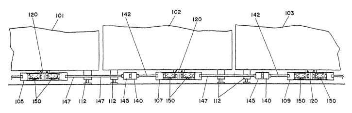
FIG. 1 is a fragmentary elevational view of adjacent modular wall panels 101,
102, 103 of a rearrangeable wall system. The wall panels are provided with
electrical
interconnection assemblies 105, 107 and 109 in a raceway area formed along the
lower edge of
panels 101, 102 and 103. Each of the panels is provided with substantially
flat support legs 112
which allow for passage of electrical conduits in the raceway. Raceway covers,
customarily
used, have been omitted from the drawing in FIG. 1 to better show the
electrical junction
assemblies. Each of the electrical interconnection assemblies 105, 107, and
109 is provided with
a junction block 120, a female electrical connector block 140 and a matching
male connector
block 145. The connector blocks 140, 145 are connected to associated junction
blocks 120 by
means of conduit sections 142 and 147, respectively. Each of the junction
blocks 120 is shown
in FIG. 1 to be provided with a pair of electrical outlet receptacles 150.
Junction blocks 120 are
16
CA 02604891 2007-10-05
WO 2007/027243 PCT/US2006/017321
double sided and corresponding pairs or outlet receptacles are provided on the
opposite side of
each of the wall panels 101, 102 and 103 (not shown in the drawing) to allow
various electrical
equipments to be plugged into the outlets from either side of the panel.
FIG. 2 is an enlarged perspective view of one of the electrical
interconnection
assemblies, for example assembly 107. The junction block 120 is provided with
support lugs
122 by which the junction block is supported by standard fasteners extended
through support
tables extending from the bottom edge of the wall panel, e.g., wall panel 102.
Junction block
120 comprises an elongated housing having opposing ends 121 and 123 and a
symmetrical center
section comprising four female receptacle connectors 126. Only one of the
receptacle connectors
126 is fully exposed in FIG. 2. There is a pair of connectors 126 on each side
of the housing and
the connection on each side face in opposite directions. Support flanges 130
are provided
adjacent each of the female connectors to provide support for electrical
outlet receptacles
engaged with the connectors 126. In this manner, junction block 120 is adapted
to support four
electrical outlet receptacles, two on each side of a wall panel to which
junction block 120 is
attached. The junction block assembly further comprises end connector block
140, provided
with a female connector 141, and connected via a standard electrical conduit
142, which may be
a flexible conduit, to end 123 of junction block 120. Similarly, connector
block 145, provided
with a male connector 146 is connected via flexible conduit 147 to end 121 of
junction block
120. In a straight line connection arrangement, as depicted for example in FIG
1, wherein a
plurality of panels are positioned adjacent each other, electrical power is
transmitted between
panels by connection of male connector block 145 to female connector block 140
of the adjacent
junction assembly.
17
CA 02604891 2007-10-05
WO 2007/027243 PCT/US2006/017321
Electrical power is transmitted through the junction assembly by means of
electrical wires disposed in the conduits 142, 147, terminated on connectors
141 and 146,
respectively, and connected to receptacle connectors 126 in junction block
120. Accordingly,
electrical power is transmitted through interconnecting panels and is at the
same time made
available at electrical outlet receptacles in each panel. Conduit 147,
provided with the male
connector block 145, may be a fixed-length conduit and conduit 142 may be of a
length such that
female connector block 140 is positioned at substantially the same distance
from the panel edge
in each panel independent of the width of the panel. Thus, female connector
block 140 will
always be accessible to male connector block 145 independent of the width of
the panels. To
accommodate panels of different widths, conduit 142 may be an expandable
flexible conduit,
such as are well known in the art. In that case, connector block 140 may be
provided with an
inner spatial area 136, as shown in a partially broken-away view in FIG. 2.
The inner spatial
area 136 is provided for storage of excess length of electrical wiring 138 in
a coiled or other
configuration. The excess length of electrical wiring 138 may be withdrawn
when conduit 142 is
expanded to an extended length. This arrangement is similar to that disclosed
in my earlier
patent, U.S. Pat. No. 4,579,403 (dated Apr. 1, 1986) and entitled ELECTRICAL
JUNCTION
ASSEMBLY WITH ADJUSTABLE CONNECTORS.
The conduit 147 is preferably a flexible conduit which may be bent to
accommodate a connection to adjacent panels which are disposed at angular
positions with
respect to each other, rather than in a straight line. The junction assemblies
of this invention
readily accommodate an arrangement in which three or more panels are disposed
in an
intersecting relationship, as will be discussed further herein with respect to
FIG. 6. In such a
configuration, the male connector block 145 of one of the panels may be
connected to one of the
18
CA 02604891 2007-10-05
WO 2007/027243 PCT/US2006/017321
female receptacle connectors 126 of a junction block assembly in an adjacent
wall panel. For
this purpose, the female connector 141 of connector block 140 and female
receptacle connectors
126 on junction block 120 have been made identical. Similarly, the male
connector 146 on
connector block 145 has been made identical to the male connector of
electrical outlet receptacle
150, shown in FIG. 1. Greater detail of the receptacle 150 is shown in FIG. 4
and is described
below. As may be seen from FIG. 2, the female connectors 126 and 141 are each
provided with
a pair of side flanges 129 having upper and lower recessed areas 128, for
engagement with
flanges 148 of a male connector to provide a locking arrangement. Figures 129,
which are made
of a resilient plastic material and formed integral to the housing to which
they are connected, are
provided with an outwardly extending inclined end surface 135. When surfaces
135 are engaged
by flanges such as flanges 148 of connector 146 on connector block 145, the
flanges 129 will be
deflected inward, allowing flanges 148 of the male connector to engage
recesses 128 to provide a
locking engagement of the male and the female connectors. A protuberance 137
is provided with
a generally rounded edge surface 139 and acts as an entry guide as a male
connector is engaged
in female connector 126. The female connectors 126, 141 are each provided with
a plurality of
female connector terminals 125 and a key lug 127. Male connector 146 is
provided with a
plurality of male connector terminals 149 and an opening 143 for receiving key
lug 127.
The electrical outlet receptacle 150, shown in FIG. 4, is provided with male
connectors 151 at both ends, allowing the receptacle to be plugged into any
one of the four
female receptacle connectors 126 of junction block 120. As shown in FIG. 2,
junction block 120
is provided with upper and lower support flanges 130 to support receptacles
150 in each of the
four female connectors 126. The lower support flanges 130 are provided with a
locking flange
132. The receptacle 150 is provided with a spring latch 152 disposed in recess
154 in the surface
19
CA 02604891 2007-10-05
WO 2007/027243 PCT/US2006/017321
156 of receptacle 150. Surface 156 engages one of the lower support flanges
130 when the
receptacle 150 is installed in the junction block 120. The locking flanges 132
will be aligned
with the recess 154 when the receptacle 150 is inserted between flanges 130,
causing the spring
latch 152 to be depressed. The receptacle 150 may then be moved to either the
left or to the right
to engage one of the female connectors 126. Recesses 158 are provided in
receptacle 150 to
accommodate locking flange 132 and movement to either the left or to the right
by a sufficient
distance will cause the spring latch 152 to be moved past locking flange 132,
causing the spring
latch 152 to return to its extended position. Hence, receptacle 150 will be
retained in a locked
position. The receptacle may be removed by depressing spring latch 152 and
sliding the
receptacle 150 to either left or right to align the locking flange 132 with
recess 154. FIG. 5 is a
right-hand elevation of receptacle 150 showing a right-hand elevation or
receptacle 150 showing
right-hand male connector 151.
FIG. 3 is a cross-sectional view of junction block 120 taken along line 3-3 of
FIG.
2. FIG. 3 shows two of the four receptacle connectors 126 of connector block
120. One of the
two connectors 126 shown in FIG. 3 is disposed on each side of the central
housing section 131,
which contains a plurality of wires 133. An eight-wire system is shown in this
illustrative
embodiment. Each of the male and female connectors are provided with eight
separate
terminals, and eight separate electrical wires 133 extend through the
connector blocks 140, 145,
the conduits 142, 147 and the central section 131 of the junction block 120.
By way of example,
these may include two ground terminal wires, three neutral wires and three
positive wires
representing three separate circuits, with a shared ground for two of the
circuits. Similarly, 10-
or 12-wire systems may be readily accommodated, having corresponding number of
terminals on
each of the connectors and providing a greater number of separate circuits.
The four female
CA 02604891 2007-10-05
WO 2007/027243 PCT/US2006/017321
receptacle connectors 126 are each connected to the wires 133 by means of a
plurality of contact
blades, described later herein with respect to Figs. 7 and 8. Each wire,
together with the
connector block terminals and receptacle connector terminals to which it is
connected, is referred
to herein as a circuit element. A particular circuit may be selected for use
by one of the
receptacles 150 by appropriate wiring connections internal to the receptacle.
Since all of the
circuits are connected to each one of the receptacle connectors 126 of
junction block 120, a
connector block 145 of an adjacent panel, equipped with a male connector, may
be connected to
any one of the receptacle connectors 126. In this manner, electrical power may
be provided to
receptacle connectors to junction block 120 and to associated connector blocks
140, 145 and
hence to any adjacent panels to which these connectors may be connected.
Similarly, a
connector block 145 equipped with a male connector connected to one of the
female connectors
126 may receive electrical power for distribution to a panel to which the
connector block 145
belongs. Such interconnecting arrangements are described further herein with
respect to FIG. 6.
FIG. 7 is a fragmentary cross-sectional view along line 7-7 of FIG. 2. Shown
in
FIG. 7 is a contact blade structure 170 which is one of eight such blades
disposed in central
housing section 131. Each such blade is in electrical contact with one of the
conductors 133.
Connection to conductor 133 is made by means of a crimped connection of blade
extension
member 172 to conductor 133. As may be more readily seen from the perspective
view of FIG.
8, the extension member 172 is part of a center section 173 which is connected
to left-hand upper
and lower contact blades 174 and right-hand upper and lower contact blades
175. The upper and
lower contact blades on each side from the female opening part of the
conductor 126 for
engagement with blades of a male connector.
21
CA 02604891 2007-10-05
WO 2007/027243 PCT/US2006/017321
FIG. 6 is a fragmentary plan view of raceway areas of four wall panels
illustrating
the connections of interconnection assemblies of the invention in a
configuration in which the
four panels are disposed at right angles to each other. As will be apparent
from the following
description, the specific angle at which the panels are positioned is not
particularly significant.
Furthermore, the invention is equally applicable to a three-panel
configuration or a five-panel
configuration disposed at right angles to each other. Each of the four panels
is provided with an
interconnection assembly, as shown in FIG. 2, comprising a junction block 120,
a male
connector block 145, and a female connector block 140 attached to the junction
block 120 by
means of flexible conduits 147 and 142, respectively. The junction block 120
is disposed within
each panel raceway near one edge of the panel. Panels 200, 201, 202 are
positioned such that the
end at which these panels are joined to other panels is the end near which the
junction block 120
is positioned. One of the panels, panel 203, is positioned with an opposite
orientation in which
the end near which the junction block 120 is located is positioned opposite
the point of junction
of the four panels. The flexible conduit 147, provided with the male connector
block 145,
extends beyond the end of the panel in which it is positioned, and the
flexible conduit 142,
provided with a female connector block 140, is terminated just short of the
end of the panel.
Thus, as is also shown in FIG. 1, a connection is made between panels by
extending the flexible
conduit 147 with male connector block 145 into the raceway area of the
adjacent panel to engage
the female connector block 140 at the end of flexible conduit 142. In the
configuration of FIG.
10 6, the male connector block 145 of panel 202 and its associated flexible
conduit 147 extend into
the raceway area of panel 202 to engage female connector block 140 of panel
203. It will be
apparent that the connection as shown between panel 202 and 203 may be made
whenever these
panels are adjacent and independent of the angle at which the panels are
disposed with respect to
22
CA 02604891 2007-10-05
WO 2007/027243 PCT/US2006/017321
each other. In the configuration of FIG. 6, the flexible conduit 147, with its
male connector
block 145, associated with the panel 200 are extended into the raceway area of
panel 202 for
engagement with one of the female receptacle connectors 126 of junction block
120 in panel 202.
In this manner, an electrical connection is established among the junction
blocks of the three
panels 200, 202, and 203. Thus, electrical power provided from an external
source to any one of
these three may be distributed to the other two by means of the connection
arrangement shown
by way of example in FIG. 6. In the arrangement of FIG. 6, flexible conduit
147 and its male
connector block 145 of panel 202 is connected to one of the female connectors
126 of junction
block 120 of panel 200 thereby establishing an electrical connection between
panels 200 and
201. This connection, in combination with the other connections shown in FIG.
6 and described
in the previous sentences, completes an arrangement for establishing an
electrical connection
from any one of four panels to the entire four-panel configuration. Additional
connections may
be envisioned by connections of male connectors 145 from other panels into
additional ones of
the female receptacle connectors 126 of the junction blocks 120 of any of the
panels 201 through
203, should one choose to provide an arrangement of more than four
intersecting panels.
Furthermore, additional conduits, such as conduit 210 shown in FIG. 6, may be
connected by
means of a male connector to any of the receptacle connectors 126 to provide
electrical power to
lamps or other fixtures. As can be seen, a great deal of flexibility has been
achieved by the
electrical junction assembly in accordance with this invention.
The foregoing description was a disclosure of an example prior art system,
adapted for use in wall panels of a space divider system. Turning to the
specific embodiment in
accordance with the invention, the junction block assembly 300 is illustrated
in FIGS. 9 - 14.
Turning to FIG. 9, the junction block assembly 300 includes a junction block
302. The junction
23
CA 02604891 2007-10-05
WO 2007/027243 PCT/US2006/017321
block 302 is characterized as being "single-sided" in that it provides for
interconnection of
receptacle blocks only on one side of the junction block 302. As further shown
in FIG. 9, the
junction block assembly 300 includes a first center connect cable assembly 304
and a second
center connect cable assembly 306. The cable assemblies 304, 306 may be
identical. As
described in greater detail in subsequent paragraphs herein, the first and
second center connect
cable assemblies 304, 306 are adapted to electrically interconnect to the
junction block 302, in a
manner so that electrical power received from one of the cable assemblies 304,
306 may be
applied to electrical receptacle blocks connected to the junction block 302
and so as to apply
power to the other of the center connect cable assemblies 304, 306. As further
illustrated in FIG.
9, the junction block assembly 300 includes a first electrical receptacle
block 308 and a second
electrical receptacle block 310. Each of the receptacle blocks 308, 310 is
adapted to be
releasably interconnected to the junction block 302 and, correspondingly, to
the cable assemblies
304, 306 so that electrical power can be supplied to receptacles associated
with the receptacle
blocks 308, 310.
Turning specifically to the junction block 302, the block 302 will now be
described with respect to FIGS. 9 - 14. FIG. 13 illustrates a pair of junction
blocks 302, and
specifically illustrates a side of one of the junction blocks 302 which
opposes the side of the
junction block 302 viewable in FIG. 9. More specifically, the junction block
302 comprises a
housing 312. The housing 312 includes a pair of recessed or spatial areas 314
and 316, referred
to herein as the first recessed area 314 and second recessed area 316. As will
be described in
subsequent paragraphs herein, the recessed areas 314, 316 are adapted to
receive, mechanically
and electrically, the electrical receptacle blocks 310, 308. Each of the first
and second recessed
areas 314, 316 is formed by a lower wall 318 and an upper wall 320. Located at
the back of each
24
CA 02604891 2007-10-05
WO 2007/027243 PCT/US2006/017321
of the recessed areas 314, 316 is a back wall 322. Each of these spatial areas
314, 316 is also
formed by an outer side wall 324 and an inner side wall 326.
Within the first recessed area 314, a first electrical connector set 328
extends
laterally from the inner side wall 326. Correspondingly, an identical second
connector set 330
extends laterally outwardly from the inner side wall 326 associated with the
second recessed area
316. Each of these connector sets 328, 330 is formed by a series of female
connectors 332. The
female connectors 332 are formed from individual contact blade structures,
somewhat
corresponding to the contact blade structure 170 previously described herein
with respect to the
prior art configurations shown in FIGS. 7 and 8. In the particular
configuration illustrated in
FIGS. 9 - 14, each of the connector sets 328, 330 comprises an 8-wire or 8-
connector system.
That is, eight separate wires are provided. By way of example, these may
include two ground
terminal connectors, three neutral connectors and three positive connectors
representing three
separate circuits incoming to the junction block assembly 300. Similarly, 5,
10 or 12 - connector
systems may be readily accommodated, having corresponding numbers of terminals
on each of
the connectors and providing for a different number of separate circuits. In
addition to the
female connectors 332 shown with respect to the first recessed area 314, a
further set of female
connectors 334 would be associated with the second connector set 330 within
the second
recessed area 316. An illustration of one of the female connectors 332 and one
of the female
connectors 334 is shown in FIG. 10.
At the back of the junction block 302 is a pair of center positioned connector
sets
336. These connector sets 336 are somewhat similar to the receptacle
connectors 126 associated
with the prior art system previously described herein. The center position
connector sets 336 are
referred to herein as a first center position connector set 338 and a second
center position
CA 02604891 2007-10-05
WO 2007/027243 PCT/US2006/017321
connector set 340. Each of these center position connector sets 338, 340
include a set of eight
female connectors 342. Each of the center position connector sets 338, 340 is
positioned in a
straight line relationship relative to the other of the connector sets 338,
340. Referring
specifically to FIG. 13, where the first center positioned connector set 338
is shown in relative
detail with respect to a second junction block 302, the first center position
connector set 338
includes a side flange 344 extending to the side of the female connectors 342.
The side flange
344 is provided with upper and lower recessed areas 346. The upper and lower
recessed areas
346 are adapted to assist in providing engagement with flanges with one of the
first or second
center connected cable assemblies 304, 306, respectively. The side flanges 344
are preferably
made of a resilient plastic material and formed integral with the housing of
the junction block
302 to which they are associated. Preferably, the side flanges 344 are also
provided with an
outwardly extending inclined end surface 348. When the surfaces 348 are
engaged by flanges
associated with the cable assemblies 304, 306, the side flanges 344 will be
deflected inwardly,
allowing flanges of the cable assemblies 304, 306 to engage the recessed areas
346, so as to
provide a locking engagement of a center position connector set 366 with a
center connect cable
assembly 304 or 306.
Each of the junction blocks 302 of the junction block assembly 300 also
includes
means for releasably coupling the junction block assembly 300 to other
structures, including, for
example, an upper wall of a raceway within a wall panel or the like. In this
regard, reference is
?0 made primarily to FIG. 13, illustrating a pair of the junction blocks 302
with a support bracket
350 having the shape and configuration specifically illustrated in FIG. 13.
The support bracket
350, as illustrated in FIG. 13, comprises an upper section 358 having a
substantially horizontal
configuration when installed within a wall panel or the like. Integral with
and extending from
26
CA 02604891 2007-10-05
WO 2007/027243 PCT/US2006/017321
opposing sides of the upper section 358 are a pair of downwardly turned
flanges 360. Extending
laterally outwardly from the other opposing sides of the upper section 358,
and curve
downwardly there from are a pair of integral side arms 362. Integral with each
of the side arms
362 and extending outwardly from the lower portions thereof are a pair of
laterally extending
retaining supports 364.
The support bracket 350 is adapted to be connected to the lower portion of a
longitudinally extending support bar 352 as illustrated in FIG. 13. Support
bar 352 has a
substantially rectangular and hollow configuration. It should be emphasized
that various other
types of support configurations and supporting components can be utilized in
place of the
support bar 352. The support bar 352 includes a bottom section 354. Through
holes 356 extend
through the upper section 358 of the support bracket 350. Corresponding
through holes (not
shown) would also extend through the bottom 354 of the support bar 352.
Connecting means,
such as screws or the like (not shown) may be received with in the through
holes 356 and the
through holes (not shown) of the support bar 352 for purposes of
interconnecting the support
bracket 350 to the support bar 352.
Returning to the junction blocks 302, each of the junction blocks 302 include
a
pair of L-shaped mounting lugs 366 located at the top of the junction block
302 and each equally
spaced from the center thereof. For purposes of securing each of the junction
blocks 302 to the
support bracket 350, the ends of the laterally extending retaining supports
364 can be received
within a corresponding one of each of the L-shaped mounting lugs 366. This
configuration is
specifically illustrated in FIG. 14, with respect to one of the junction
blocks 302 and a pair of the
mounting lugs 366.
27
CA 02604891 2007-10-05
WO 2007/027243 PCT/US2006/017321
As shown primarily in FIGS. 9 and 13, each of the junction blocks 302 further
includes what could be characterized as a latching device 368 positioned on
the tops of the
junction blocks 302 and centered with respect to the longitudinal length of
each of the junction
blocks 302. With reference to FIGS. 9, 12 and 13, each of the latching devices
368 includes an
interlocking latch member 369. The interlocking latch member 369 is provided
with an
elongated member such as the cantilever beam 372. The cantilever beam 372 is
attached to the
top of the corresponding junction block 302 by means of a moving hinge 370.
The interlocking
latching member 369 may be integrally formed on the top of the corresponding
junction block
302, and may be constructed of a resilient plastic material, such as
polycarbonate which provides
a restoring force on the interlocking latch member 369. The cantilever beam
372 includes an
upwardly sloping surface 374 which slops upwardly toward the back of the
corresponding
junction block 302. At the end of the sloping surface 374 is a tab 376. When
the support bracket
350 is appropriately mounted in the ends of the retaining supports 364 are
received within the L-
shaped mounting lugs 366, the cantilever beam 372 moved toward a corresponding
downwardly
turned flange 360 of the support bracket 350, and the tab 376 engages the
flange 360. This
configuration is illustrated with respect to one of the junction blocks 302
and one of the latching
devices 368 in FIG. 14. When it is desired to disengage a junction block 302
from a support
bracket 350, a downwardly projecting force (either by hand, screwdriver or the
like) may exerted
on the upwardly sloping surface 374, so as to depress the cantilever beam 372.
When the
cantilever beam 372 is depressed, the tab 376 of the cantilever beam 372 will
move below the
end of the corresponding downwardly turned flange on the support bracket 350.
In this manner,
the retaining tab 376 is disengaged from the flange 360. The junction block
302 may then be
removed from the L-shaped mounting lugs 366, by pulling the junction block 302
outwardly
28
CA 02604891 2007-10-05
WO 2007/027243 PCT/US2006/017321
from the support bracket 350. Specifically, this outward movement of the
junction block 302
will cause the mounting lugs 366 to be disengaged from the retaining supports
364 of the support
bracket 350. Similarly, the junction block 302 may be installed and releasably
interconnected
with the support bracket 350 by slidably engaging the L-shaped mounting lugs
366 with the
retaining supports 364. This sliding motion will result in engagement of the
latching device 368
with the downwardly extending flange 360, thereby causing the tab 376 to be
captured by the
flange 360. At that point, the restoring force imparted to the latching device
368 due to the
resiliency of the interlocking latch member 369 causes engagement of the tab
376 with the flange
360, thereby placing the junction block 302 in a releasably locked position
relative to the
supporting bracket 350.
A slightly modified embedment of the junction block 302 illustrated in FIGS. 9
and 13 is shown in FIGS. 10, 11 and 12. Therein, the modified junction block
302 is configured
so as to be releasably secured to a pair of support brackets 350 (not shown in
FIGS. 10, 11 or
12). That is, as specifically shown primarily in FIGS. 10 and 11, the modified
junction block
302 includes two pairs of L-shaped mounting lugs 366, with each pair mounted
on one side of
the top of the junction block 302. Correspondingly, intermediate the mounting
lugs 366 of each
pair is a latching device 368. Accordingly, the modified junction block 302
includes two
latching devices 368. The latching devices 368 and the mounting lugs 366 of
the modified
junction block 302 shown in FIGS. 10, 11 and 12 operate in exactly the same
manner as the
mounting lugs 366 and latching device 368 illustrated with respect to the
junction blocks 302
illustrated in FIGS. 9 and 13. However, with the configuration shown in FIGS.
10, 11 and 12,
one support bracket 350 would be utilized with one latching device 368 and a
pair of the
mounting lugs 366, while a second support bracket 350 would be utilized with
the second
29
CA 02604891 2007-10-05
WO 2007/027243 PCT/US2006/017321
latching device 368 and second pair of mounting lugs 366. This configuration
could be
characterized as providing somewhat greater support for the modified junction
block 302, in that
two support brackets 350 are utilized to mount the junction block 302 to a
support bar 352.
Turning back to the electrical assemblies associated with the junction block
assembly 300, the first and second center position connector sets 338, 340,
respectively, were
previously described herein. For purposes of providing electrical power to the
connector sets
338, 340, and for transmitting power through the connector sets 338, 340, the
junction block
assembly 300 includes a first center connect cable assembly 304 and a second
center connect
cable assembly 306, as previously referenced herein. Turning primarily to FIG.
9, the first center
connect cable assembly 304 is identical to the second center connect cable
assembly 306. With
respect to each of the cable assemblies 304, 306, each assembly includes a
connector block 383
at a terminating end of each of the assemblies 304, 306. Each connector block
383 includes an
outwardly extending male connector set 380. Each male connector set 380
includes a series of
male connector terminals 382. As previously referenced, the junction block
assembly 300 shown
in FIG. 9 can be characterized as an "8-wire" assembly. Accordingly, each male
connector set
380 would, correspondingly, comprise a set of eight male terminals 382.
Electrical power is
transmitted to and through the junction block assembly 300 by means of
electrical wires (not
shown) disposed in an adjustable cable or conduit section 384. The wires (not
shown) within the
cable or conduit section 384 terminate at the male connector terminals 382 of
the corresponding
male connector block 383. Although not shown in the drawings, the adjustable
cable or conduit
section 384 may terminate at its other end in a corresponding male connector
block 383 or other
electrical assemblies. For example, the other end of either or both adjustable
cable or conduit
CA 02604891 2007-10-05
WO 2007/027243 PCT/US2006/017321
section 384 may terminate in a connector adapted to interconnect directly to
cables associated
with incoming building supply power or other direct sources of electrical
power.
As previously described herein, each of the center positioned connector sets
338,
340 is provided with a side flange 344 having upper and lower recessed areas
346. The upper
and lower recessed areas 346 are adapted to assist in providing engagement
with flanges 386 of
one of the male connector sets 380. In this manner, a releasable locking
engagement is provided
between a male connector set 380 and a center positioned connector set 338 or
340. As also
previously described herein, the side flanges 344 of the center positioned
connector sets 338 and
340 are preferably made of a resilient plastic material and formed integral
with the housing of the
junction block 302 to which they are associated. Preferably, side flanges 344
are also provided
with an outwardly extending inclined end surface 348. When the inclined end
surfaces 348 are
engaged by flanges, such as the flanges 386 of the male connector set 380 on a
connector block
383 of a center connect cable assembly 304, 306, the flanges 344 will be
deflected inwardly,
allowing the flanges 386 of the male connector set 380 to engage the recesses
346, and thereby
provide a locking engagement of the center connect cable assembly 304, 306,
and a male
connector set 380. Preferably, each of the center positioned connector sets
338 and 340 are
provided with a key lug 388. Correspondingly, each male connector set 380 is
preferably
provided with an opening 390 for receiving the corresponding key lug 388. In
accordance with
the foregoing, the first and second center position connector sets 338, 340,
respectively, can be
mechanically (in a releasable manner) and electrically interconnected to
either of the first center
connect cable assembly 304 or the second center connect cable assembly 306.
As earlier described herein, the junction block assembly 300 includes one or
more
junction blocks 302. Each junction block 302 is adapted to electrically
receive a first receptacle
31
CA 02604891 2007-10-05
WO 2007/027243 PCT/US2006/017321
block 308 and a second receptacle block 310, as illustrated in FIG. 9. FIG. 9
illustrates
prospective views of each of the receptacle blocks 308, 310. In this
particular embodiment of
receptacle blocks which may be utilized in accordance with the invention, each
of the receptacle
blocks 308, 310 is provided with a first male connector set 394 extending
outwardly from one
end of each of the receptacle blocks 308, 310, and an identical second male
connector set 396
extending outwardly from an opposing end of each of the receptacle blocks 308,
310. With
respect to FIG. 9, the actual terminals of the second male connector set 396
in each of the
receptacle blocks 308, 310 is not actually viewable. However, each of the
second male
connector sets 396 as the exact same configuration as each of the first male
connector sets 394.
In this regard, providing male connector sets 394, 396 at both ends of the
receptacle blocks 308,
310 permits the receptacle blocks 308, 310 to be utilized with a junction
block having a
configuration such as junction block 302, wherein a first female connector set
328 is located
within a first recessed area 314, and a second female connector set 330 is
located within the
second recessed area 316. That is, with the male connector sets 394, 396
associated with each of
the receptacle blocks 308, 310, either of the receptacle blocks 308, 310 can
be utilized in either
of the recessed areas 314, 316.
As also previously described, the junction block 302 is provided with the open
recessed areas 314, 316 in which to support the electrical receptacle blocks
308, 310. In the
same regard, each of the first and second male connector sets 394, 396,
include a series of male
terminals 398. The male terminals 398 comprise blade terminals. Typically, a
receptacle block
308 or 310 would comprise three blade terminals, corresponding to a single
circuit to be applied
from the blade terminals 398 to the electrical receptacles 400 which extend
outwardly from the
front of each of the receptacle blocks 308, 310. The electrical receptacles
400 illustrated in FIG.
32
CA 02604891 2007-10-05
WO 2007/027243 PCT/US2006/017321
9 comprise three terminal receptacles, and would include a hot, neutral and
ground connection.
The receptacles 400 are in the form of female terminals, and are adapted to
receive conventional,
electrical 3-prong plugs (not shown) electrically connected to devices and
appliances to be
energized. As an example, each of the electrical receptacles 400 may include a
hot terminal 402,
neutral terminal 404 and ground terminal 406. Each of these terminals of this
receptacle 400 is
connected to a different one of the blade terminals 398 associated with the
connector sets 394,
396.
The bottom portion of each of the receptacle blocks 308, 310 is not
illustrated in
FIG. 9. However, these bottom portions may have a latching mechanism
substantially similar to
the latching mechanism previously described herein with respect to the prior
art receptacle block
150. That is, with reference to the junction block 302, the recessed area 314
is provided, on its
lower wall 318, with a slightly recessed locking flange 408. Correspondingly,
the recessed area
316 associated with the junction block 302 also includes on the lower wall
318, a substantially
identical locking flange 408. However, as illustrated in FIG. 9, the locking
flange 408 associated
with the recessed area 314 is positioned to one side of an indentation 410 in
the lower wall 318,
while the locking flange 408 associated with the recessed area 316 is
positioned to an opposing
side of an indentation in the lower wall 318 of the recessed area 316.
Although not specifically shown in FIG. 9, but as previously described with
respect to the receptacle block 150 associated with the prior art system
illustrated in FIGS. 4 and
5, the lower portion of each of the receptacle blocks 308, 310 is provided
with a spring latch (not
shown) disposed within a recess (not shown) on an underside of each of the
receptacle blocks
308, 310. Each of the receptacle blocks 308, 310 can be inserted into the
recessed areas 314, 316
of the junction block 302. With the configuration shown in the exploded view
of FIG. 9, the first
33
CA 02604891 2007-10-05
WO 2007/027243 PCT/US2006/017321
receptacle block 308 can be inserted into the second recessed area 316 so that
the electrical
receptacles 400 face outwardly from the spatial area 316 illustrated in FIG.
9. When inserted,
the locking flange 408 will cause the spring latch (not shown) of the
receptacle block 308 to be
depressed. The receptacle block 308, with the partial recessed area 316 shown
in FIG. 9, may be
inserted into the recessed are 316 and then be moved to the left (in the view
shown in FIG. 9) so
that the male terminals 398 of the first male connector set 394 are
electrically engaged with the
second connector set 330 having female connectors 334 within the recessed area
316. Further,
the receptacle block 308 will also include recesses (not shown) so as to
accommodate the locking
flange 408. Movement to the left of the receptacle block 308 by a sufficient
distance will cause
the spring latch (not shown) to be moved passed the locking flange 408,
thereby causing the
spring latch to return to its extended position. In this manner, the
receptacle 308 is physically
maintained in a locked but releasable position. The receptacle 308 may be
removed from
electrical connection with the female receptacle block 330 by depressing the
spring latch (not
shown) and sliding the receptacle 308 to the right so as to align the locking
flange 408 with the
recessed area of the receptacle block 308. With this configuration, the
receptacle block 308 may
be removed from the recessed are a316.
Correspondingly, the receptacle block 310 may be physically moved into
engagement within the recessed area 314, and then slid to the right so that
the male connector set
396 will electrically engage the female connector set 328 associated with the
recessed area 314.
the recessed area 314 has a locking flange 410, which functionally corresponds
to locking flange
408 previously described with respect to recessed area 316. Also, the
receptacle block 310, like
the receptacle block 308, will include a spring latch (not shown) disposed
within a recess (not
shown) in a lower surface of the receptacle block 310. The functional and
mechanical operation
34
CA 02604891 2007-10-05
WO 2007/027243 PCT/US2006/017321
of engaging and disengaging the receptacle block 310 from the junction block
302 corresponds
to the same operations as previously described with respect to receptacle
block 308 and the
junction block 302. Accordingly, the same will not be repeated herein.
As previously described herein, each of the junction blocks 302 includes a
first
center position connector set 338 and a second center positioned connector set
340. These
connector sets are primarily shown in FIG. 13. As also previously described,
the connector sets
338, 340 are adapted to electrically engage the male connector sets 380
associated with each of
the cable assemblies 304, 306. It should be emphasized that a continuous
electrical path exists
between the female connectors 342 associated with the first center position
connector set 338 and
the female connectors 342 associated with the second center position connector
set 340.
Correspondingly, as also previously described, each of the junction blocks 302
includes a first
female connector set 328 associated with the recessed area 314, and a second
female connector
set 330 associated with the recessed area 316. The female connectors 332
associated with the
first female connector set 328 are in a continuous electrical path with the
corresponding female
connectors 334 associated with the second female connector set 330. Still
further, there is a
continuous electrical path between connectors associated with the first center
position connector
set 338, second center position connector set 340, first female connector set
328 and second
female connector set 330. This configuration can be achieved through the use
of what can be
characterized as an H-shaped connector used with respect to each of the eight
terminals
associated with the female connector sets coupled to each of the junction
blocks 302. One of the
H-terminals is illustrated in substantial part in FIGS. 10 and 12, and is
referred to therein as H-
connector 414. As apparent with an 8-wire system, eight of the H-connectors
414 would be
utilized. A connector somewhat corresponding to the H-connector 414 was
previously described
CA 02604891 2007-10-05
WO 2007/027243 PCT/US2006/017321
herein with respect to the prior art illustrations of FIGS. 7 and 8, and was
referred to as a contact
blade structure 170. With reference to FIGS. 7 and 8, and further with
reference to FIGS. 10 and
12, each of the H-connectors 414 associated with the junction block 302 in
accordance with the
invention would substantially correspond to one of the contact blade
structures 170 illustrated
with respect to FIGS. 7 and 8, but with the contact blade structure 170 having
the blade
extension member 172 removed. In the prior art configuration illustrated in
FIGS. 7 and 8, the
blade extension member 172 is utilized to connect to a conductor by means of a
crimped
connection. As illustrated in FIGS. 10 and 12, each of the H-connectors 414
includes a series of
four contact blade sets 416 each of the contact blade sets 416 includes upper
and lower contact
blades as substantially shown as contact blades 174 and 175 in prior art FIG.
8. As shown
expressly in FIG. 10, the contact blade sets 416 form an H-shaped
configuration. A common
conductor 418 extends between all four of the contact blade sets 416, and
provides an electrically
conducted path there between. Again, it should be emphasized that with an 8-
wire system, eight
of the H-connectors 414 would be utilized, and would essentially be stacked as
illustrated in FIG.
12. As further illustrated in FIG. 10, one arm of each of the H-connectors 414
would correspond
to the female terminals associated with the second center position connector
set 340.
Correspondingly, an opposing arm would correspond to the female connectors of
the first center
position connector set 338. Still further, and positioned within the recessed
area 314, one set of
arms of the H-connectors 414 would correspond to the first female connector
set 328.
Correspondingly, the remaining arm of each of the H-connectors 414 would
correspond to a
female terminal of the second female connector set 330.
In accordance with all of the foregoing, an assembly of the junction block
assembly 300 will now be described, with respect to essentially all of the
FIGS. 9 - 14. In
36
CA 02604891 2007-10-05
WO 2007/027243 PCT/US2006/017321
accordance with the prior discussion, a pair of the junction blocks 302 can be
mechanically
assembled to a support bracket 350 as shown in FIG. 13. As also shown in FIG.
13, the support
bracket 350 can then be connected to a support bar 352. The support bar 352
may be an upper
portion of a supporting structure for a raceway or the like. If desired, two
of the junction blocks
302 can be connected to the support bracket 350, at opposing ends thereof.
After such connection, the first center connect cable assembly 304 can be
electrically and mechanically connected to the second center position
connector set 340.
Correspondingly, the second center connect cable assembly 306 can be
mechanically and
electrically connected to the first center position connector set 338. With
these connections, I am
assuming that electrical power is being transferred from either the first
center connect cable
assembly 304 or the second center connect cable assembly 306, electrical power
is thereby
supplied to both the first female connector set 328 within the recessed area
314 of junction block
302, and the second female connector set 330 located within the recessed area
316 of the
junction blocks 302. As previously described, in the particular embodiment
illustrated herein,
each of the connector sets 328, 330 may comprise eight female connectors,
representing three
separate circuits, with each circuit having a hot, neutral and ground
connection. Following this
assembly, one or more of the first receptacle block 308 and/or second
receptacle block 310 may
be electrically engaged with the connector sets 328, 330 of the junction block
302. In the
particular configuration illustrated in FIG. 9, a second male connector set
396 associated with the
second receptacle block 310 would be electrically engaged with the first
connector set 328 within
the recessed area 314. Correspondingly, the first receptacle block 308, having
a first male
connector set 394, would be electrically engaged to the second connector set
330 within the
recessed area 316 of junction block 302. As also previously described, the
first and second male
37
CA 02604891 2007-10-05
WO 2007/027243 PCT/US2006/017321
connector sets 394, 396, respectively, would have three "active" male
terminals 398 associated
with each connector set. These three terminals 398 would be located so that
they would
electrically engage with one hot, one neutral and one ground connector of
either the first
connector set 328 or the second connector set 330. In this manner, a selected
one of the three
available circuits would be provided as electrical power to each of the
electrical receptacles 400
associated with the receptacle blocks 308, 310.
With the foregoing configuration, a junction block has been provided with two
electrical receptacle blocks, so as to provide a total of four electrical
receptacles 400 associated
with the junction block 302. Correspondingly, and with primary importance in
accordance with
the invention, the junction block 302 is adapted so as to provide for a
"center connect" of
electrical power from center connect cable assemblies 304, 306 to the junction
block 302. This
center connect type of configuration is particularly useful in certain
situations where the junction
blocks 302 and the raceways into which the junction blocks 302 may be
installed have particular
relative sizes and configuration.
As earlier described, it is advantageous to provide for a raceway system which
can accommodate raceways of varying widths, without necessarily changing the
structures of the
junction blocks or electrical receptacle blocks. One such raceway system is
illustrated as
raceway system 500, with raceway system 500 and various embodiments thereof
being described
with respect to FIGS. 15 - 42 in subsequent paragraphs herein. With reference
first to FIG. 15, a
raceway system 500 includes a junction block 502 having a housing 503. A cable
assembly 504
is attached to one end of the junction block housing 503. The cable assembly
504 includes a
cable connector 506 utilized to structurally secure the cable assembly 504 to
the junction block
housing 503 by any suitable and well known means. The cable connector 506 is
attached to a
38
CA 02604891 2007-10-05
WO 2007/027243 PCT/US2006/017321
conduit 508. The conduit 508 may hold a plurality of electrical conductors,
depending upon the
number of conductors and electrical circuits utilized with the particular
raceway system 500.
The conduit 508 may be flexible in design. Also, for purposes of accommodating
distance
requirements between and among junction blocks, the conduits 508 utilized with
the raceway
system 500 may be adjustable and comprise expandable, flexible conduit. For
purposes of
providing such adjustability, end connector blocks (not shown) may be provided
with an inner
spatial area. The inner spatial area can be provided for storage of excess
length of electrical
wiring in a coiled or other similar configuration. This type of arrangement is
illustrated with
respect to the end connector block 140 as previously described herein and
illustrated in FIG. 2.
Similar types of arrangements are disclosed in my earlier patents, U.S. Patent
Nos. 5,096,434
issued March 17, 1992 and 4,579,403 issued May 1, 1986.
Turning again to the junction block 502, the block 502 includes female
connector
block pairs 510 extending outwardly from the opposing end of the junction
block 502. Each of
the female connector block pairs 510 includes a female connector set 512. Each
of the female
connector sets 512 of each female connector pair 510 is provided with a side
flange 514 having
upper and lower recessed areas 516. The upper and lower recessed areas 516 are
adapted to
assist in providing engagement with cable assemblies (not shown) which may be
structurally and
electrically attached to the female connector block pairs 510.
The upper and lower recessed areas 516 of the female connector block pairs 510
are adapted to assist in providing engagement with flanges of a male or end
connector block (not
shown) associated with a cable assembly. In this manner, a releasable locking
engagement can
be provided between a female connector set 512 and male connector terminals
(not shown) of a
39
CA 02604891 2007-10-05
WO 2007/027243 PCT/US2006/017321
male or end connector block. The side flanges 514 may be made of a resilient
plastic material
and formed integral with the housing of the junction block 502 which they are
associated.
Preferably, the side flanges 514 are also provided with an outwardly extending
inclined end surface. When these surfaces are engaged by flanges of male
connectors, the side
flanges 514 will be deflected inwardly, allowing flanges of the male connector
to engage the
recessed areas 516, thereby providing a releasable locking engagement of the
male and female
connectors. Preferably, each of the female connector sets 512 is provided with
a plurality of
female connector terminals 538 and a key lug 540. Concepts associated with
such configurations
are disclosed and illustrated in FIGS. 2 and 3, and further disclosed in my
U.S. Patent No.
5,096,434 issued March 17, 1992 and entitled ELECTRICAL INTERCONNECTION
ASSEMBLY. Turning again specifically to the junction block 502, FIG. 15
illustrates one side
of the junction block 502 while FIG. 21 illustrates an opposing side of the
junction block 502.
The junction block 502 comprises the housing 503, which includes a pair of
recessed areas 520,
522 on opposing sides of the junction block 502. As described in subsequent
paragraphs herein,
and is apparent from prior description of the prior art assemblies illustrated
herein, the recessed
areas 520, 522 are adapted to receive, mechanically and electrically, the
electrical receptacle
block 542, which will be described in subsequent paragraphs herein. Each of
the recessed areas
520, 522 is formed by a lower wall 524 and an upper wall 526. Located at the
back of each of
the recessed areas 520, 522 is a back wall 528. Each of these spatial areas
520, 522 is also
formed by a side wall 530.
Within the first recessed area 520, a first electrical connector set 532
extends
longitudinally outwardly from the side wall 530. Correspondingly, an identical
second connector
set 534 extends longitudinally outwardly from the side wall 530 associated
with the second
CA 02604891 2007-10-05
WO 2007/027243 PCT/US2006/017321
recessed area 522. Each of these connector sets 532, 534 is formed by a series
of vertically
disposed "half-H" terminals 536, primarily illustrated in FIGS. 22, 23 and 24.
As shown therein,
each of the terminals 536 includes a pair of longitudinally extending female
terminals 544.
These female terminals 544 extend outwardly and form the female connector sets
512 previously
described herein, which are part of the female connector block pairs 510.
Electrically connected
to the female terminals 544 is a blade terminal 546 which extends laterally
and perpendicular to
each of the pair of female terminals 544. The blade terminals 546 (only one of
which is shown
in each of FIGS. 22, 23 and 24) form both the first connector set 532 and the
second connector
set 534 associated with the junction block 502. In this manner, the connector
sets 532, 534 are
electrically connected to each other, since each is formed by the same blade
terminal 546.
As further shown in FIGS. 22, 23 and 24, a rear terminal 548 extends
rearwardly
from the blade terminal 546. The rear terminal 548 extends rearwardly and
includes a crimp
assembly 550. The crimp assembly 550 is utilized to electrically connect the
half-H terminal 536
to an electrical conductor 552. The electrical conductor 552 extends from the
rear terminal 548
through the cable connector 506 and into the conduit 508. In this manner, the
conductors 552
may be used in substitution of any bus bar assemblies or similar assemblies
which may exist in
conventional junction blocks. It is apparent that this saves on costs
associated with metal utilized
within the junction block 502.
Each of the blade terminals 546 is vertically disposed relative to other blade
terminals 546 within the junction block 502, and is held in place by
conventional means. In the
particular configurations illustrated in FIGS. 15 - 42, the connector sets
utilized therein comprise
8-wire or 8-connector systems. That is, eight separate conductors 552 are
utilized, so as to
provide 8 terminals. By way of example, these may include two ground terminal
conductors,
41
CA 02604891 2007-10-05
WO 2007/027243 PCT/US2006/017321
three neutral conductors and three positive conductors, representing three
separate circuits
incoming to the raceway system 500. Similarly, five, ten or twelve-connector
systems may be
readily accommodated, having corresponding numbers of terminals on each of the
connectors
and providing for a different number of circuits. Terminals such as the half-H
terminals 536
have been previously illustrated herein and described with respect to FIGS. 7
and 8, although the
terminals shown in FIGS. 7 and 8 typically are characterized as "full" H-
terminals.
The junction block 502 of the raceway assembly 500 also includes means for
releasably coupling the junction block 502 to other structures including, for
example, an upper
wall of a raceway within a wall panel or the like. In this regard, with
reference to FIGS. 15 and
19, the junction block 502 includes a pair of L-shaped mounting lugs 554
located at the top of
the junction block 502, and each equally spaced from the center thereof. The L-
shaped mounting
lugs 554 can be utilized to secure the junction block 502 to a support bracket
(not shown) which
could correspond to the support bracket 350 previously described herein with
respect to FIG. 13.
The interconnecting configuration is specifically illustrated in FIG. 14, with
respect to one of the
previously described junction blocks 302 and pair of mounting lugs 366.
As primarily shown in FIGS. 15 and 19, the junction block 502 further includes
what can be characterized as a latching device 556 positioned at the top of
the junction block 502
and centered with respect to the longitudinal length of the junction block
502. The latching
device 556 can be utilized to secure the junction block 502 to a support
bracket (not shown) or a
similar structure for interconnection of the junction block 502 to the raceway
of a wall panel or
the like. Various types of latching mechanisms may be utilized for the
latching device 556. One
such latching mechanism is disclosed in my U.S. Patent No. 5,259,787 issued
November 9, 1993
42
CA 02604891 2007-10-05
WO 2007/027243 PCT/US2006/017321
and entitled LATCHING MECHANISM. Latching devices are also disclosed in my
U.S. Patent
No. 4,993,576 issued February 19, 1991.
The following paragraphs will now describe the electrical receptacle block
542. It
should be emphasized that the receptacle block 542 can be similar in structure
and function to the
electrical receptacle blocks 308, 310 previously described herein and
illustrated in FIG. 9. The
electrical receptacle block 542 is structured as primarily shown in FIGS. 15
and 18, and includes
a pair of opposing female connector sets 558. The female connector sets 558
include a series of
female terminals 560. These terminals 560 and female connector sets 558 are
formed through a
series of vertically disposed receptacle terminal assemblies 562 located
within the receptacle
block 542. These receptacle terminal assemblies 562 are illustrated primarily
in FIGS. 22, 23
and 24. As shown therein, the receptacle block 542 includes what can be
characterized as an
elongated bus bar 566. The female terminals 560 are formed at the opposing
ends of the bus bar
566. Extending perpendicularly from the bus bar 566 are a pair of female
receptacle terminals
564. These terminals will be associated with either a hot, neutral or ground
terminal of a three-
prong receptacle 568, as described in subsequent paragraphs herein.
Typically, the receptacle block 542, for a 8-wire system, would comprise three
of
the receptacle terminal assemblies 562, corresponding to a single circuit to
be applied from the
first or second connector sets 532, 534 to the electrical receptacle block
542. With respect to the
electrical receptacle block 542, an external face 567 includes a pair of
electrical receptacles 568
as illustrated in FIG. 15. The electrical receptacles 568 each include three
terminal receptacles,
namely hot, neutral and ground connections. The receptacles 568 are in the
form of female
terminals, and correspond to the female receptacle terminals 564 previously
described herein
with respect to FIGS. 22 - 24. As an example, each of the electrical
receptacles 568 may include
43
CA 02604891 2007-10-05
WO 2007/027243 PCT/US2006/017321
a hot terminal 570, neutral terminal 572 and ground terminal 574. Each of
these terminals of
each receptacle 568 is associated with a different one of the receptacle
terminal assemblies 562.
Concepts associated with some of the principal concepts of the raceway system
500 in connection with the invention will now be described. With reference
first to FIGS. 15-18,
and as specifically shown in FIG. 15, the lower wall 524 on each side of the
junction block 502
includes a series of lower receptacle channels 576. In the particular
embodiment shown in FIG.
15, three lower receptacle channels 576 are illustrated. Correspondingly,
directly above the
lower receptacle channels 576 are a series of corresponding upper receptacle
channels 578. As
with the lower receptacle channels 576, the upper receptacle channels 578 are
three in number.
As shown in FIG. 17, the lower receptacle channels 576 and upper receptacle
channels 578 exist
on both sides of the junction block 502.
With reference primarily to FIG. 18, and as illustrated therein, the
electrical
receptacle block 542 includes a lower tab 580 which extends longitudinally
along the entire
bottom portion of the receptacle block 542. Correspondingly, as also
illustrated in FIG. 15 and
FIG. 18, an upper tab 582 extends longitudinally along the entire upper
portion of the receptacle
block 542. In accordance with the invention, the lower tab 580 is adapted to
selectively engage
one of the lower receptacle channels 576 of the junction block 502.
Correspondingly, the upper
tab 582 is adapted to engage one of the upper receptacle channels 578 on the
upper wall 526 of
the junction block 502. The particular pair of channels 576, 578 chosen by a
user will cause the
receptacle block 542 to be adjusted in dimensions regarding how far laterally
outwardly the
receptacle block 542 extends, relative to the junction block 502. In this
manner, in accordance
with the invention, the "effective" width of the raceway assembly 500 can be
selectively
adjusted, using only a single size of junction block 502 and electrical
receptacle block 542.
44
CA 02604891 2007-10-05
WO 2007/027243 PCT/US2006/017321
The general concept of this configuration is illustrated in FIGS. 22, 23 and
24.
Therein, one of the receptacle terminals 562 associated with the receptacle
block 542 is shown in
various positions. For example, if the receptacle block 542 is engaged in an
inner set of channels
576, 578, the receptacle terminal assembly 562 will be in the position shown
in solid line format
in FIG. 22. In this manner, the receptacle block 542 can be moved toward the
"right" (as viewed
in FIG. 15) so that the female connector set 558 on one side of the block 542
can electrically
engage the first connector set 532 associated with the junction block 502.
This engagement
corresponds to the engagement of one of the female terminals 560 of the
receptacle terminal
assembly 562 with the blade terminal 546 associated with the half-H terminal
536. FIG. 23
illustrates the relative configuration of a receptacle terminal assembly 562
when the receptacle
block 542 is selectively engaged with the middle set of receptacle channels
576, 578.
Correspondingly, FIG. 24 illustrates the relative position of a receptacle
terminal assembly 562
of the receptacle block 542, when the receptacle block 542 has its tabs 580,
582 respectively
engaged with the outermost receptacle channels 576, 578.
FIGS. 27-30 illustrate a second raceway assembly 600 which is somewhat similar
to the raceway assembly 500. Accordingly, elements of raceway assembly 600
similar in
structure and function to like elements of raceway assembly 500 include
reference numerals
corresponding to those of the like elements in the raceway assembly 500. With
reference first to
FIG. 27, the raceway assembly 600 includes a junction block 602. The junction
block 602
includes a first connector set 604 which comprises a series of female
terminals 606. In this case,
the female terminals 606, as illustrated in FIGS. 31 and 32, are part of a
half-H terminal 608
which is somewhat different in structural configuration from the half-H
terminal 536 previously
described herein. More specifically, the half-H terminal 608 includes a pair
of outwardly
CA 02604891 2007-10-05
WO 2007/027243 PCT/US2006/017321
extending female terminals 610. These outwardly extending female terminals 610
correspond to
the female terminals of the female connector sets 512. These female terminals
610 are connected
to a perpendicularly extending common terminal blade 613. The blade 613 is
electrically
connected to the pair of rearwardly extending female terminal 606. The female
terminals 606
may extend rearwardly into the recessed areas 520, 522, so as to be accessible
to an electrical
receptacle block. It should be noted that in this particular configuration,
the terminals made
accessible to the electrical receptacle block are female terminals 606, rather
than the blade
terminal 546. As with the previously described half-H terminal 536, a rear
terminal 548 is
electrically connected to the female terminal 606 and 610, and includes a
crimp assembly 550 at
the end of the rear terminal 548. The crimp assembly 550 is utilized to
connect the rear terminal
548 to the conductors 552, which extend though the junction block 602 and into
the conduit 508.
The raceway assembly 600 includes an electrical receptacle block 612. The
receptacle block 612 includes a number of structures and components similar to
those of the
receptacle block 542, and such elements are numbered identically to those
corresponding
elements of block 542. However, the receptacle block 612 is relatively wider
than the receptacle
block 542, and includes receptacle terminal assemblies 614 having a
configuration different than
the receptacle terminal assembly 562 previously described herein with respect
to the receptacle
block 542. Also, the receptacle block 612 may include a set of receptacles 568
only on one side
of the block 612. With respect to the receptacle terminal assemblies 614, each
includes a pair of
?0 receptacle terminals which are perpendicularly configured and located at
the terminating ends of
elongated bus bar 618. In this instance, unlike the receptacle block 542, the
receptacle terminal
616 are male terminals. With the configuration illustrated in FIGS. 27-32, the
receptacle block
612 can again be located in any one of three channels 576, 578. However,
unlike the raceway
46
CA 02604891 2007-10-05
WO 2007/027243 PCT/US2006/017321
system 500, the connector terminals 606 associated with the junction block 602
are in the form
of female terminals. Correspondingly, the receptacle terminal assembly 614
associated with the
receptacle block 612 includes a set of male terminals, rather than the female
terminal 560
associated with the receptacle block 542.
FIGS. 33-38 illustrate a further raceway system 650. As with the raceway
system
600, some of the elements of the raceway system 650 are similar in structure
and function to
elements of the raceway system 500. Such elements of the raceway system 650
are numbered
identically to the corresponding elements of raceway system 500.
Turning to FIGS. 33-38, the raceway system 650 includes a junction block 652
having a structure which is substantially different from those of the junction
block 602 and the
junction block 502. In the junction block 652, the block has an H-shaped
configuration, with an
upper wall 654 and lower wall 656. A series of back walls 658 also exist as
illustrated in FIG.
33. These walls form a set of four recessed areas 660. The recessed areas 660
are adapted to
electrically and structurally receive the receptacle block 542. For use with
the raceway system
600, a cable assembly 662 can be employed. The cable assembly 662 has a cable
connector 664
and a pair of flexible conduits 666. Two connector set pairs are employed,
with each having a
series of eight female terminals 668. As illustrated in FIGS. 37 and 38, the
female terminals 668
are conventional in design and connect to a series of conductors 670 through a
crimp assembly
671.
ZO As primarily shown in FIGS. 37 and 38, each of the female terminals 668 can
be
electrically and releasably connected to a common blade terminal 672. The
common blade
terminal 672 can be rectangular in configuration, and is adapted to
electrically and releasably
47
CA 02604891 2007-10-05
WO 2007/027243 PCT/US2006/017321
receive female terminals 668 from the cable assembly 662. These can be
received from either of
two opposing directions relative to the junction block 652.
The electrical receptacle block used with the raceway system 650 can
correspond
completely in structure and function to the previously described receptacle
block 542 used with
the raceway system 500. With reference to FIGS. 37 and 38, the receptacle
block 542 includes
opposing receptacle connector sets 558. As shown in FIGS. 37 and 38, the
receptacle connector
sets 558 comprise receptacle terminal assemblies 674 having opposing female
terminals 676 at
the ends thereof, with an elongated bus bar 678 extending longitudinally
through the receptacle
block 542. With this configuration, female terminals 676 exist at the opposing
ends of the
elongated bus bar 678. When the receptacle block 542 is engaged within one of
these sets of
channels 576, 578, and electrically engaged with the common blade terminal
672, electrical
connections are made between the receptacles 568 and the conductors 670
running through the
conduits 666. Again, it is noted that with the raceway system 650, a
substantial amount of metal
is saved, relative to other raceway systems adding the same functional
capabilities.
A further raceway system in accordance with the invention is illustrated as
raceway system 700 in FIGS. 39-42. In this particular configuration, a
junction block 702 is
provided. The junction block 702 is substantially similar to the previously
described junction
block 502. However, instead of having a set of three channels 576, 578, the
junction block 702
includes a series of five lower channels 704 and a corresponding series of
five upper channels
706. The raceway system 700 also includes a receptacle block 708. The
receptacle block 708
substantially corresponds to the receptacle block 542 previously illustrated
in FIG. 15 and
described herein. However, unlike receptacle block 542, the receptacle block
708 has a series of
receptacles 568 only on one side of the block 708. The absence of receptacles
on the opposing
48
CA 02604891 2012-05-22
side of the receptacle block 708 is to accommodate the receptacle block 708
when it is
engaged in the innermost channels 704, 706 of the receptacle block 702. Also
for
purposes of accommodating the five channels 704, 706, it can be seen from FIG.
42
that the upper tab 710 and lower tab 712 are offset from a center line of the
receptacle
block 708. This is to permit the upper tab 710 to be engaged with the
innermost upper
channel 706, and the lower tab 712 to be engaged with the innermost lower
channel
704. With respect to male and female connectors and terminals, the receptacle
block
708 could include male terminals, while the connector set 532 could include
female
terminals. However, if desired, the connector set 532 could include male
terminals,
while the receptacle block 708 could include female terminals.
In accordance with the foregoing, raceway systems have been described which
accommodate raceways of varying widths, without requiring differing sizes and
configurations of junction blocks and electrical receptacle blocks.
It will be apparent to those skilled in the pertinent arts that still other
embodiments of raceway assemblies in accordance with the invention can be
designed. That is the principles of a raceway assembly in accordance with the
invention are not limited to the specific embodiments described herein.
Accordingly,
it will be apparent to those skilled in the art that modifications and other
variations of
the above-described illustrative embodiments of the invention may be effected
without departing from the scope of the novel concepts of the invention.
49