Note: Descriptions are shown in the official language in which they were submitted.
CA 02604893 2007-10-10
WO 2007/095121 PCT/US2007/003574
RADIALLY EXTENDED SUPPORT MEMBER FOR SPINAL NUCLEUS
IMPLANTS AND METHODS OF USE
CROSS REFERENCE TO RELATED APPLICATIONS
The present application claims the benefit and priority of provisional
application serial no. 60/772,504 filed on February 10, 2006 and titled
RADIALLY
EXTENDED SUPPORT MEMBER FOR SPINAL NUCLEUS IMPLANTS AND
METHODS OF USE. The entire contents of Ser. No. 60/772,504 are hereby
incorporated in its entirety herein.
BACKGROUND
Spinal nucleus implants are known. For example, U.S. Pat. Nos. 5,562,736
and 5,674,295 disclose an implant having a constraining jacket surrounding a
hydrogel core. As described therein, a hydrogel material is dehydrated,
resulting in an
undersized substantially cylindrical gel capsule which is then inserted into
the
constraining jacket which is then closed to prevent the hydrogel from escaping
the
confines of the jacket. The implant is rehydrated and conditioned by a series
of
compressive loads which renders the nucleus body to a partially flattened or
oval
shape. The implant is then inserted into a retaining tube to maintain the oval
shape up
until implantation. Altemative embodiments include an outer skin fonned by ion
implantation which causes outer layer polymerization and functions as the
constraining jacket. U.S. Pat. No. 6,022,376 describes an implant made from an
amorphous hydrogel polymer core surrounded by a constraining jacket. In one
embodiment, the amorphous polymer is poured into one end of the constraining
jacket
in an unhydrated state, and the jacket then closed. The implant is then
massaged to
flatten and narrow the implant in preparation for implantation. Alternatively,
the
amorphous polymer may be injected into the constraining jacket. In one
embodiment,
an empty constraining jacket is implanted into the disc space and the
amorphous
polymer is then injected into the constraining jacket. In one embodiment, the
amorphous polymer is shaped into a plurality of "microchips" which have been
manufactured to have a certain shape. U.S. Pat. No. 6,132,465 is directed to a
nucleus
implant having a hydrogel core in a constraining jacket. The hydrogel core is
inserted
into the constraining jacket in a wedge-shaped dehydrated state and then
implanted
into the nucleus cavity. A final dehydration step is described where the
hydrogel core
CA 02604893 2007-10-10
WO 2007/095121 PCT/US2007/003574
can be forced into certain shapes, i.e., it can be "entirely flat". U.S. Pat.
No.
6,602,291 describes a prosthetic spinal disc nucleus which is made with a
hydrogel
core having a first shape in the hydrated state. It is then placed in a
constraining
jacket and reshaped to have a second shape in the dehydrated state. The core
is
configured to transition from the second shape to the first shape on
hydration. The
second shape may include an elongated shape defined by a leading end, the
hydrogel
core tapering from the central portion to the leading=end, to facilitate
insertion through
an opening in the annulus. An inherent shape memory attribute is said to be
obtained
by pouring a hydrogel material, suspended in a solvent into a mold having a
shape
corresponding to the desired hydrated shape. After a solvent exchange process,
the
hydrogel core is dehydrated in an oven and inserted into a constraining
jacket. The
implant is then rehydrated and subjected to conditioning steps by exposure to
at least
three compressive loads. The implant is then reshaped and dehydrated, i.e., it
is
placed into a mold having a streamlined shape and then placed in an oven to
expedite
dehydration of the hydrogel core, which causes the implant to have a
streamlined
shape. The implant may be compressed while dehydrating_ The implant is then
maintained in the dehydrated shape prior to implantation. U.S. Pat. No.
6,533,817 is
directed to a packaged, partially hydrated prosthetic disc nucleus which
includes a
prosthetic disc nucleus and a retainer. Upon contact with a hydration liquid,
the
retainer is said to be configured to allow the hydrogel core to hydrate from
the
dehydrated state but prevents the core from hydrating to the final hydrated
state, i.e.,
the prosthetic disc nucleus is constrained by the retainer to a partially
hydrated state.
As described therein, a hydrogel core is formed and placed within a
constraining
jacket. The prosthetic disc nucleus is then dehydrated, preferably under
compression
within a compression mold and the entire assembly is placed in an oven. As the
core
dehydrates the compression mold forces the nucleus to a desired dehydrated
shape in
the dehydrated state. The dehydrated disc nucleus, in the dehydrated state is
then
placed in the retainer. The packaged disc nucleus can then be exposed to a
hydration
liquid where it transitions to the partially hydrated state. Once removed from
the
retainer, the disc nucleus, in the partially hydrated state is implanted into
the disc
space. U.S. Pat. No. 5,047,055 is directed to a hydrogel intervertebral disc
nucleus.
As described therein, a prosthetic nucleus for a disc is composed of a
hydrogel
material. The nucleus is made by mixing polyvinyl alcohol with a solvent
heating the
mixture and then poured or injected into a mold. The shaped hydrogel can be
2
CA 02604893 2007-10-10
WO 2007/095121 PCT/US2007/003574
dehydrated for implantation. Other hydrogel materials are also described which
can
be shaped by cast molding or lathe cutting. The volume of the nucleus is said
to
reduce by about 80% when dehydrated and that the rigidity of the dehydrated
nucleus
will help the surgeons to manipulate the nucleus during an operation. U.S.
Pat. No.
5,534,028 is directed to a hydrogel intervertebral disc nucleus with
diminished lateral
bulging and describes certain hydrogel treatment procedures which are similar
to
those disclosed in U.S. Pat. No. 5,047,055, e.g., see the implantation
discussion at
column 11, lines 25-40.
Surgical procedures for replacing or augmenting damaged or diseased nucleus
pulposus involve anterior approaches or posterior approaches to the spinal
column.
The posterior approach (from the back of the patient) encounters the spinous
process,
superior articular process, and the inferior articular process to allow
insertion of the
disc replacement material into the intervertebral space, i.e., the bony sheath
lies
directly in front of each vertebral disc. The anterior approach to the spinal
column is
complicated by the intemal organs that must be bypassed or circumvented to
access
the vertebrae. Thus, surgery is typically complicated and time consuming. An
posterior-lateral aspect approach is the least invasive of these methods but
provides
limited and oblique access to the disc and its interior.
A potential shortcoming of artificial disc replacements is the propensity for
extrusion of the implant through the annulus. The nucleus pulposus is held in
place
by the annulus in vivo. However, the annulus must be compromised in order to
gain
access to the diseased or damaged disc space. The resulting annular defect
provides a
path of least resistance through which a nucleus replacement or augmenter may
travel
under extremes of load and/or motion. In the case of implants which are made
from a
soft material, e.g., a hydrogel from polyvinyl alcohol, the propensity for
extrusion
through creep or flow is higher as the material gets softer. The likelihood of
extrusion
also increases with increased load.
The likelihood of extrusion occurring may further be increased by a poor
implant cross-section to annular incision size ratio. The higher this ratio,
the less
likely it is that the implant will extrude. For example, if a 5 mm o implant
is placed
into the disc space through a 5 mm o incision the implant cross-section to
annular
3
CA 02604893 2007-10-10
WO 2007/095121 PCT/US2007/003574
incision ratio is 1.0 and extrusion is highly likely. It is therefore
advantageous to keep
this ratio as high as possible by reducing the incision size. This can be
facilitated by
decreasing the cross section of the implant which must pass through the
annulus. In
designing implants to be used with minimally invasive techniques, the cross-
sectional
area of the implant should be as small as possible. Although some of the above-
described implants are dehydrated and shaped in some manner, none of them are
dehydrated and reshaped so as to force the implant to assume an implantation-
friendly
shape substantially different from the final, hydrated implanted shape. Thus,
the
implant's original footprint may be maintained in the form of a wafer, which
may
have an aspect which is decreased along one axis, but not the other.
Alternatively,
isotropic shrinkage from dehydration may be effected which does not alter the
topography of the implant. In the case of simple dehydration, the cross-
sectional area
is equal to the hydrated cross-sectional area divided by the expansion ratio.
Another method of optimizing the implant cross section for minimally
invasive surgery is partial hydration of a hydrogel material which allows for
nianipulation of the implant by the surgeon with or without specialized tools
designed
for this purpose. There are a number of potential drawbacks to partial
hydration or
plastification such as incompatibility of the plasticizer used with the
sterilization
method, difficulty of retaining the required amount of plasticizer within the
package
over extended periods and the possibility of creep occurring during storage.
Accordingly there is a need to reduce the possibility that a spinal nucleus
implant will extrude from the disc space through the annulus. Various methods
have
been proposed including physical barriers which span an annular defect. See,
e.g., US
Pat. No. 6,883,520. Additional extrusion resistance may be obtained by
mechanical
attachment of the implant to the annulus by sutures, staples, clips and other
fasteners.
Such attachment methods may be problematic in the case of viscoelastic
implants
such as high water content hydrogels where the hydrogel matrix does not
provide
much resistance to tearing out of the fastener from the implant.
The present invention addresses at least these problems by providing a spinal
nucleus implant which contains, inter alia, a novel interiorly embedded
support
member.
4
CA 02604893 2007-10-10
WO 2007/095121 PCT/US2007/003574
SUMMARY
A spinal nucleus implant is provided which includes an implant body and an
interiorly embedded support member which extends out from the implant body. In
one embodiment, the body has an ellipsoid footprint. The interiorly embedded
support
member is preferably disposed within the implant body in substantially
parallel
orientation to the footprint and preferably extends beyond the body
substantially
parallel to the footprint. In one embodiment, the support member extends
radially
beyond and around the entire periphery of the body. In another embodiment, the
support member extends beyond a defined portion(s) of the periphery of the
body. In
one embodiment, the support member is configured to extend and be folded over
a
portion of the surface area of the body. In one embodiment, the support member
is
configured to extend and be folded over a majority of the surface area if the
body. In
one embodiment, the support member is fabric selected from the group
consisting of
mesh, woven fabric and nonwoven fabric. The fabric may be made, e.g., from
natural
or synthetic polymers or metal fibers. In another embodiment, the support
member is
a foil made from metal or a polymer. In one embodiment, the body is made of at
least
two layers and the support member located between two layers. In one
embodiment,
the body is made of alternating substantially parallel layers wherein at least
one of the
layers contains the support member. In one embodiment, the support member is
at
least partially encapsulated by a polymeric coating. In one embodiment, the
support
member includes at least one portion which is located outside of the body,
said
portion adapted to engage a guide for orienting the implant. The guide may be
selected from the group consisting of wire, ribbon or string. In one
embodiment, a
plurality of guides are attached to the support member. In one embodiment, the
guide
is releasably affixed to the support member. In another embodiment, the
support
member is adapted to promote ingrowth of tissue. In one embodiment, the
support
member incorporates a medicinal agent which promotes tissue growth. In one
embodiment, the body is made of a hydrogel such as a polyacrylonitrile
hydrogel. In
one embodiment, the implant is capable of expanding from a compact,
substantially
dehydrated configuration to an expanded hydrated configuration.
A spinal nucleus implant is also provided which includes an implant body and
an elongate flexible guide member affixed to the implant body. The guide
member is
CA 02604893 2007-10-10
WO 2007/095121 PCT/US2007/003574
preferably selected from the group consisting of wire, ribbon or string such
as a
suture. In one embodiment, the guide member is affixed to a support member
which is
embedded to the interior of the implant body. In one embodiment, the guide
member
is releasably affixed to the support member. In one embodiment, a plurality of
guide
members are attached to the support member. In one embodiment, the support
member is fabric selected from the group consisting of mesh, woven fabric and
nonwoven fabric. In another embodiment, the support member is a foil made from
metal or a polymer. In one embodiment, the implant body is made of a hydrogel
such
as a polyacrylonitrile hydrogel. In one embodiment, the implant body
incorporates
layers, wherein certain layers have a different modulus of elasticity compared
to other
layers. In one embodiment, at least one of the layers includes a support
member
having a polymeric coating. In one embodiment, the implant is capable of
expanding
from a compact, substantially dehydrated configuration to an expanded hydrated
configuration.
A method of manufacturing a spinal nucleus implant is provided which
includes providing a liquid polymer, providing a mold for containing the
polymer,
providing a support member, positioning the support member relative to said
mold
such that liquid polymer can at least partially cover the support member, and
coagulating the liquid polymer such that at least a portion of said support
member
extends beyond the perimeter of the polymer to form a spinal nucleus implant
having
an interiorly disposed support member which extends out of the polymer. In one
embodiment, the mold includes a first ellipsoid ring portion for receiving
liquid
polymer and a second ellipsoid ring portion for disposing over the first
ellipsoid ring
portion and receiving liquid polymer, wherein positioning the support member
relative to the mold involves filling the first ring with said liquid polymer,
placing the
support member over the first ring such that at least a portion of said
support member
extends beyond the perimeter of the first ring, positioning the second ring
coaxially
over the first ring and the support member to produce a substantially liquid-
tight
arrangement between the first and second rings, filling the second ring with
liquid
polymer, and coagulating the liquid polymer to form the spinal nucleus implant
having an interiorly disposed support member which extends out of the polymer.
In
one embodiment, the method further includes providing a first additional
ellipsoid
ring mold, filling the first additional mold with liquid polymer, placing the
implant
6
CA 02604893 2007-10-10
WO 2007/095121 PCT/US2007/003574
having an interiorly disposed support member coaxially over the first
additional
ellipsoid ring mold and in contact with the liquid polymer, and coagulating
the liquid
polymer such that the polymer adheres to the implant having an interiorly
disposed
support member as it coagulates to form a spinal nucleus implant having a
first
polymeric layer containing the support meinber and a second polymeric layer,
wherein the support member extends beyond the perimeter of the polymeric
layers. In
one embodiment, the first polymer layer containing the support member has a
different modulus of elasticity than the second polymeric layer_ In one
embodiment,
the method further includes providing a second additional ellipsoid ring mold,
placing
said second additional mold coaxially over the first polymer layer containing
the
support member, filling the mold with liquid polymer, and coagulating the
liquid
polymer such that the polymer adheres to the first polymer layer containing
the
support member as it coagulates, to form a three polymeric layer spinal
nucleus
implant wherein the support member extends beyond the perirneter of at least
one of
the polymeric layers. In one embodiment, the method further includes providing
a
second polymeric layer containing a support meniber, placing the second
polymeric
layer containing the support member coaxially over the second ellipsoid ring
mold
and in contact with the liquid polymer contained by the second ellipsoid ring
mold,
and coagulating the liquid polymer such that the polymer adheres to the second
polymeric layer containing the support member as it coagulates, to form a four
polymeric layer spinal nucleus implant. In one embodiment, the method further
includes providing a third additional ellipsoid ring mold, placing said third
additional
mold coaxially over the second polymeric layer containing the support member,
filling the third additional ellipsoid ring mold with liquid polymer, and
coagulating
the liquid polymer such that the polymer adheres to the second polymeric layer
containing the support member as it coagulates, to form a five polymeric layer
spinal
nucleus implant. In one embodiment, the modulus of elasticity of the
coagulated
polymer of the polymeric layers having interiorly disposed support members is
greater than the modulus of elasticity of the layers which do not have an
interiorly
disposed support member. In one embodiment, the liquid polymer is a hydrogel.
In
one embodiment, the hydrogel is a polyacrylonitrile hydrogel. In one
embodiment, the
support member is a fabric selected from the group consisting of woven,
nonwoven
and mesh. In another embodiment, the support member is a foil made from metal
or a
7
CA 02604893 2007-10-10
WO 2007/095121 PCT/US2007/003574
polymer. In one embodiment, at least one guide member is attached to the
support
member.
A method of implanting a spinal nucleus implant is provided which includes
providing a spinal nucleus implant having a proximal portion and a distal
portion, the
distal portion having an elongated flexible guide member affixed thereto, the
guide
member having a proximal end and a distal end, the proximal end being affixed
to the
distal portion of the implant, providing a point of entry to the disc space
between two
vertebrae, inserting the implant into the disc space using the distal portion
of the
implant as the leading portion of the implant through the point of entry,
manipulating
the guide member to cause the implant to change position. In one embodiment,
manipulating the guide member causes the implant to cant in arcuate fashion.
In one
embodiment, the distal portion of the implant follows an arc ranging from -45
to
---100 relative to the proximal portion. The guide member may be selected
from the
group consisting of a string such as a suture, a wire and a ribbon. In one
embodiment,
the guide member is affixed to an interiorly embedded support member which
extends
out from the implant body, the guide member being affixed to a portion of the
support
member which extends out from the implant body. In one embodiment, the distal
end
of the guide remains outside the point of entry and manipulating the guide
includes
pulling on the guide member to pull the distal portion of the implant along
the arc. In
another embodiment, the method of implanting a spinal nucleus implant further
includes providing a second point of entry to the disc space, using a grasping
instrument to grasp the guide member from within the disc space, and using the
grasping instrument to pull on the guide member and cause the implant to
change
position. In one embodiment, the change in position is a canting of the
implant. In one
embodiment, the proximal portion of the spinal implant has a second guide
member
attached thereto which may be used to manipulate the position of the implant.
In one
embodiment, the implant is fastened to a portion of the annulus using a
fastener which
fastens the support member to the annulus. In one embodiment, at least one
guide
member is at least partially radiopaque. In one embodiment, after the guide
member
has been manipulated to cause the implant to change position, at least a
portion of the
guide member is removed from the support member. In one embodiment, the at
least a
portion of the guide member is removed from the support member by cutting a
portion of the guide member.
8
CA 02604893 2007-10-10
WO 2007/095121 PCT/US2007/003574
BRIEF DESCRIPTION OF THE FIGURES
FIG. I is a top view of a spinal nucleus implant having an ellipsoid implant
body and an interiorly embedded mesh support member spanning the entire body
and
extending out from opposite ends of the body.
FIG.2 is a top view of a spinal nucleus implant having an ellipsoid implant
body and an interiorly embedded mesh support member partially spanning the
entire
body and extending out from opposite ends of the body.
FIG. 3 is a top view of a spinal nucleus implant having an ellipsoid implant
body and an interiorly embedded mesh support member spanning the entire body
and
extending out around the entire periphery of the body.
FIG. 4 is a top view of a spinal nucleus implant having an ellipsoid implant
body and an interiorly embedded mesh support member partially spanning the
entire
body and extending out of a portion of the body.
FIG. 5 is a top view of a spinal nucleus implant having an ellipsoid implant
body and an interiorly embedded foil support member spanning the entire body
and
extending out from opposite ends of the body.
FIG. 6 is a top view of a spinal nucleus implant having a kidney-shaped
ellipsoid implant body and an interiorly embedded mesh support member spanning
the entire body and extending out around the entire periphery of the body.
FIG. 7 is a side view of a spinal nucleus implant having a support member
embedded interiorly and extending out beyond the perimeter of the implant
body.
FIG. 8 is a side view of a multilayer spinal nucleus implant having five
alternating substantially parallel layers, wherein the second and forth layers
contain
interiorly embedded support members. The support member of second layer
extends
out beyond the perimeter of the implant body.
FIG. 9 is a top view of a spinal nucleus implant having an ellipsoid implant
body, an interiorly embedded mesh support member spanning the entire body and
extending out from opposite ends of the body, and two guide members
respectively
affixed at opposite outwardly extending ends of the support member.
FIG. 10 is a schematic top view of an annulus surrounding a disc space,
wherein a dehydrated spinal nucleus implant is shown partially inserted
through the
annulus into the disc space. A guide member extends from the leading edge of
the
implant back through the annulus.
9
CA 02604893 2007-10-10
WO 2007/095121 PCT/US2007/003574
FIG. 11 is a schematic top view of the annulus surrounding a disc space from
FIG. 10, wherein the dehydrated spinal nucleus implant is shown completely
inserted
through the annulus into the disc space. The guide member extends from the
leading
edge of the implant back through the annulus. The schematic depicts the result
of a
slight pull on the guide member which causes the leading edge of the implant
to cant
sideways.
FIG. 12 is a schematic top view of the annulus, disc space and implant shown
in FIGs. 10 and 11, wherein the guide member has been further pulled to cause
the
implant to cant transverse to its position when first inserted.
FIG. 13 is a schematic top view of an annulus surrounding a disc space,
wherein a dehydrated spinal nucleus implant is shown partially inserted
through a first
point of entry in the annulus into the disc space. A first guide member
extends from
the leading edge of the implant through a second point of entry in the
annulus. A
second guide member is attached to the trailing edge of the implant.
FIG. 14 is a schematic top view of the annulus surrounding the disc space
shown in FIG. 13, wherein the dehydrated spinal nucleus implant is shown
completely
inserted through the annulus into the disc space. The first guide member
extends from
the leading edge of the implant through the second point of entry in the
annulus. The
second guide member extends from the trailing edge of the implant back through
the
first point of entry in the annulus. The schematic depicts the result of a
slight pull on
the first guide member which causes the leading edge of the implant to cant
sideways.
FIG. 15 is a schematic top view of the annulus, disc space and implant shown
in FIGs. 13 and 14, wherein the first guide member has been further pulled to
cause
the implant to cant perpendicular to its position when first inserted. The
second guide
member is used to stabilize the proximal portion of the implant.
FIG. 16 is a schematic top view of an annulus surrounding a disc space,
wherein a dehydrated spinal nucleus implant is shown partially inserted
through the
annulus into the disc space. A guide member extends from the leading edge of
the
implant and is contained with the disc space.
FIG.17A is a schematic top view of the annulus surrounding a disc space from
FIG. 16, wherein the dehydrated spinal nucleus implant is shown completely
inserted
through the annulus into the disc space. The guide member extends from the
leading
edge of the implant and is contained with the disc space.
CA 02604893 2007-10-10
WO 2007/095121 PCT/US2007/003574
FIG. 17B is a schematic top view of the annulus surrounding a disc space from
FIG. 16, wherein the dehydrated spinal nucleus implant is still partially
inserted
through the annulus into the disc space. The guide member extends from the
leading
edge of the implant through the second point of entry in the annulus.
FIG. 18 is a schematic top view of the annulus surrounding the disc space
shown in either FIGs. 17A or 17B, wherein the dehydrated spinal nucleus
implant is
shown completely inserted through the annulus into the disc space. The guide
member
extends through a second point of entry. The schematic depicts the result of a
slight
pull on the guide member which causes the leading edge of the implant to cant
sideways.
FIG. 19 is a schematic top view of the annulus, disc space and implant shown
in FIGs. 16 through 18, wherein the guide member has been further pulled to
cause
the implant to cant perpendicular to its position when first inserted.
DETAILED DESCRIPTION
A spinal nucleus implant ("SNI") according to the present disclosure is
uniquely suited for implantation into the disc space of a diseased or damaged
intervertebral disc by virtue of a novel interiorly embedded support member
which
extends beyond the perimeter of the body of the implant. The support member is
anchored in the body of the implant and provides reinforcement to the body of
the
implant which increases structural integrity, creep resistance and assists in
preventing
radial bulging of the implant under load bearing conditions. In addition, the
portion of
the support member which extends beyond the body of the implant provides an
advantageous modality for guiding the implant into the disc space during
implantation, anchoring the implant within the disc space, and/or providing a
substrate for ingrowth of natural tissue, e.g., fibrous collagen, thus
providing an
additional anchoring mechanism for the implant.
A support member according to the present disclosure is suitable for use as a
reinforcing element in any suitable polymeric-based SNI which can be formed
from a
liquid polymer. It is also suitable for use in any SNI (natural or synthetic)
that is made
from layers which are adhered to each other. The support member occupies at
least a
portion of the interior of the implant. The support member is preferably in
the fonn of
11
CA 02604893 2007-10-10
WO 2007/095121 PCT/US2007/003574
a fabric or a foil, but may also be a series of individual fibers or ribbons
which are
arranged in parallel or non-parallel fashion. The fabric may be woven or non-
woven
and may be in the form of a mesh. The size of interstices in the mesh is not
deemed
critical and it is contemplated that various mesh sizes are suitable. A fabric
support
member may be made of a polymeric material which is natural, e.g., cotton, or
synthetic, e.g., polyester, polyamide, or other materials such as metal fiber,
fiber
glass, and carbon fiber. Methods of making fabric from these materials and
others are
well-known to those skilled in the art. Foils herein may also be made of metal
or
polymeric material and are well-known. Thus, the support member may be
constructed from relatively durable materials including, but not limited to,
metal foil,
metal fibers, polymeric fibers of materials such as polycarbonate,
polyethylene,
polypropylene, polystyrene, polyethylene terephthalate, polyamide,
polyurethane,
polyurea, polysulfone, polyvinyl chloride, acrylic and methacrylic polymers,
expanded polytetrafluoroethylene (Goretex ), ethylene tetrafluoroethylene,
graphite,
etc. Polyester mesh made of DacronCa3 (commercially available from E. I. du
Pont de
Nemours and Company) or nylon are especially suitable. These materials can be
used
either alone, or in a composite form in combination with elastomers or
hydrogels.
Especially advantageous are mesh, woven, non-woven, perforated, or porous
formats
of these materials which will allow solid anchoring in the implant body.
In one embodiment, the implant body may consist of a single polymeric layer
in which a support member is embedded. See, e.g., FIG. 7. Alternatively, the
support
layer may be embedded by being sandwiched between two polymeric layers of the
same or differing composition. The polymer can anchor the support member by
occupying and surrounding the interstices of a fabric support member and/or by
use of
an adhesive such as a cyanoacrylate which bonds the support member and the
polymer. In a preferred embodiment, at full operational size, the SNI may be
composed of at least two substantially parallel soft layers of an elastically
deformable
polymer such as a hydrogel and at least one relatively rigid layer interposed
therebetween, the rigid layer having less compressibility than the soft
layers, being
adjacent to the soft layers, substantially parallel to them, and firmly
attached to them.
In some embodiments, the soft layers have the same thickness and/or
composition. In
other embodiments, the soft layers may have different thickness and/or
composition.
The implant body may have more than one rigid layer. The rigid layers may have
the
12
CA 02604893 2007-10-10
WO 2007/095121 PCT/US2007/003574
same or different thickness and/or composition. In one embodiment, the number
of
soft layers is one more than the number of rigid layers, with, e.g., at least
three soft
layers. See, e.g., FIG. 8. A support member is preferably embedded in at least
one of
the relatively rigid layers. It is contemplated that a rigid layer may itself
be composed
of at least two rigid layers to form a composite rigid layer. A support member
can be
embedded within or between two of the rigid layers to form a composite rigid
layer.
As used herein, "rigid layer" or "rigid reinforcing layer" are intended to
encompass a
single rigid layer and composite rigid layers. As used herein, "full
operational size"
means the intended final dimensional configuration assumed by the SNI when
implanted in a disc space.
In a preferred embodiment, the implant body is made of hydrogel and is disc-
shaped, i.e., cylindrical with a generally ellipsoid footprint when hydrated.
The
support member may also have a configuration which generally corresponds to
the
shape of the SNI body footprint when the implant body is at operational size,
e.g., the
support member having a flat substantially ellipsoid configuration when the
implant
body has a substantially ellipsoid footprint. See, e.g., FIG. 3. As used
herein,
"substantially" is intended to mean any of "approximately", "nearly" or
"precisely." It
is also contemplated that the support member may have a shape which is
independent
of the implant body footprint. Examples of different configurations are shown
in
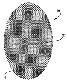
FIGs. 1 through 8. FIG. 1 is a top view of a SNI 10. A relatively circular
elliptical
implant body 12 overlays a more elliptical mesh support member 14. The support
member 14 spans the entire ellipsoidal footprint area of the implant body 12
and
extends past the implant body 12 at two opposing ends of the ellipsoid. It is
preferred
that the support member 14 span the entire interior of the implant body 12 to
allow a
maximum area of adhesion. A support member can, however, be configured to span
less than the entire interior of the implant body. See, e.g., FIGs. 2 and 4.
FIG. 2 is a
top view of a SNI 10' in which a relatively circular elliptical implant body
12
overlays a more elliptical mesh support member 14'. In this instance, the
support
member 14' does not span the entire ellipsoidal footprint area of the implant
body 12,
i.e., an aperture in the central portion of the support member 14' is empty.
The
support member 14' extends past the perimeter of the implant body 12 at
opposite
ends. FIG. 4 is a top view of another SNI embodiment 30 in which a circular
elliptical
implant body 32 overlays a portion of a semi-elliptical support member 34. The
13
CA 02604893 2007-10-10
WO 2007/095121 PCT/US2007/003574
support member 34 extends past only one portion of the implant body 32. FIG. 5
is a
top view of a SNI 40 in which a relatively circular elliptical implant body 12
overlays
an elliptical foil support member 42. The support member 42 spans the entire
ellipsoidal footprint area of the implant body 12 and extends past the implant
body 12
at two opposing ends of the ellipsoid. In certain embodiments, a support
member
extends radially beyond the entire perimeter of the implant body. See, e.g.,
FIGs. 3
and 6. FIG. 3 is a top view of a SNI 20 in which an elliptical implant body 22
overlays a correspondingly shaped mesh support member 24. The support member
24
extends radially beyond the entire perimeter of the implant body 22. FIG. 6 is
a top
view of a SNI 50 in which a kidney-shaped ellipsoidal implant body 52 overlays
an
elliptical ellipsoidal mesh support member 14. The support member 14 spans the
entire ellipsoidal footprint area of the implant body 52 and extends past the
entire
perimeter on the body 52. In other embodiments, a support member extends
beyond
one or more defined portions of the perimeter of the implant body. See FIGs.
1, 2, 4
and 5. Regardless of whether the support member extends past defined portions
of the
implant body, or the entire perimeter, such extension preferably extends
beyond the
implant body in substantially parallel orientation relative to the implant
body. See,
e.g., FIGs. 7 and 8. FIG. 7 is a side view of a single layer SNI 10 having an
interiorly
embedded support member 14 which extends beyond the periphery of an implant
body 12. FIG. 8 is a side view of a five-layer SNI 100. Three softer layers
102
alternate between two more rigid reinforcing layers 104 and 104' which contain
interiorly embedded support members. One support member 104' is completely
contained within the implant body while the other support member 104 extends
beyond the perimeter of the implant body. The amount that the support member
extends past the implant body in any of the embodiments described herein may
vary
based on the intended use of the externally disposed portion of the support
member.
In one embodiment, the perimeter portion of the support member contains barbs
for
engaging and anchoring to annulus fibers. The barbs may be incorporated at the
ends
of fibers which make up the mesh, woven, or nonwoven fabric support member.
Methods of providing barbed fibers are well-known in the art. For example,
barbs
may be cast, or physically rendered by blades. Alternatively, barbs may be
etched into
the body of the fibers using well-known laser techniques.
14
CA 02604893 2007-10-10
WO 2007/095121 PCT/US2007/003574
The implant body may be formed of any biocompatible elastomeric material,
i.e., capable of plastic deformation without fracture. Examples include, but
are not
limited to, natural rubber, silicone, polychloroprene, fluropolymers such as
Viton ,
ethylene propylene diene monomer (EPDM) rubber, polyurethane, polystyrene,
polyvinyl chloride and the like. Hydrogels are especially advantageous for use
in
forming an implant body herein. Many hydrogel polymers can be deformed, frozen
into a deformed shape and can maintain that shape indefinitely or until, e.g.,
a
temperature change causes the polymer to "relax" into the shape originally
held prior
to freezing. This property is often referred to as shape memory or frozen
deformation
by those skilled in the art.
The temperature at which frozen deformation occurs is referred to as the glass
transition temperature or Tg. At Tg several polymer properties such as
density,
entropy and elasticity may sharply change. Many polymers can be mixed with
agents
that can have a drastic effect on a polymer T.. Polymers which absorb fluid
are of
particular interest and water is the preferred Tg altering agent. Hydrogels
which
contain less than about five percent water may be considered dehydrated or
xerogels.
The Ts of a xerogel will change as it absorbs fluids containing water. Once
the Tg,
becomes lower than ambient, the now partially hydrated hydrogel becomes pliant
and
may be elastically deformed. If the polymer is held in a state of elastic
deformation
while the Tg is raised above ambient the polymer will maintain the deformed
state
indefinitely. This can be accomplished by either lowering the ambient
temperature
(freezing) or by returning the polymer to its xerogel state thus raising the
Tk.
Using this method, hydrogel articles may be produced with vastly differing
xerogel shapes compared to hydrated shapes. This is especially useful in cases
such
as medical implants where, in delivering a prosthesis into the human body,
every care
should be taken to reduce trauma to the patient. An implant which is shaped as
a
cylindrical disc having an ellipsoidal footprint, for instance, may re-shaped,
into a
tapered elongate rod in order to facilitate minimally invasive implantation.
In a
preferred embodiment, the support member is flexible, but relatively
inelastic, which
allows the support member to be bent or folded when the implant body is
dehydrated
and/or shaped to a compact configuration. An advantage of relative
inelasticity is that
the support member will not stretch to any large degree, thereby assisting in
CA 02604893 2007-10-10
WO 2007/095121 PCT/US2007/003574
maintaining the radial dimension of the implant body under load conditions.
Once the
implant is indwelling and has absorbed water containing liquids it will
substantially
return to the shape of the cylindrical ellipsoidal disc and maintain that
shape
indefinitely. As used herein, "disc" is intended to include a round, flattened
structure
of cylindrical dimension.
Suitable polymers for use in fabricating an implant body herein may contain
one or more polymeric components. Preferably, such polymers are made of
polymeric
components having a C--C backbone. Suitable polymers, such as
polyvinylalcohol,
polyvinyl pyrrolidone or derivatives of polyacrylic or polymethacrylic acid,
are more
resistant to biodegradation than polymers with heteroatoms in their backbones,
such
as polyurethanes or polyesters. Preferably, at least one of the polymeric
components
contains both hydrophilic and hydrophobic groups.
A preferred polymer configuration includes two polymer phases of different
hydrophilicity, the less hydrophilic phase having higher content of
hydrophobic
groups
and more hydrophilic phase having higher content of hydrophilic groups. The
less
hydrophilic phase is preferably crystalline and more hydrophilic phase is
preferably
amorphous, as can be established from X-ray diffraction.
Advantageous hydrophobic groups are pendant nitrile substituents in 1,3
positions on a polyrnethylene backbone, such as poly(acrylonitrile) or
poly(methacrylonitrile). The hydrophilic phase may preferably contain a high
concentration of ionic groups. Preferred hydrophilic groups are derivatives of
acrylic
acid andJor rnethacrylic acid including salts, acrylamidine, N-substituted
acrylamidine, acrylamide and N-substituted acryl amide, as well as various
combinations thereof. A particularly preferred combination contains
approximately
two thirds acrylic acid and its salts (on molar basis), the rest being a
combination of
plain and N-substituted acrylamides and acrylamidines.
At least one polymeric component is preferably a multiblock copolymer with
alternating sequences of hydrophilic and hydrophobic groups. Such sequences
are
usually capable of separating into two polymer phases and form strong
physically
16
CA 02604893 2007-10-10
WO 2007/095121 PCT/US2007/003574
crosslinked hydrogels. Such multiblock copolymers can be, for example,
products of
hydrolysis or aminolysis of polyacrylonitrile or polymethacrylonitrile and
copolymers
thereof. For convenience, polymers and copolymers having at least about 80
molar %
of acrylonitrile and/or methacrylonitrile units in their composition may be
referred to
as "PAN". Hydrolysis and aminolysis of PAN and products tbereof are described,
for
example, in U.S. Pat. Nos. 4,107,121; 4,331,783; 4,337,327; 4,369,294;
4,370,451;
4,379,874; 4,420,589; 4,943,618, and 5,252,692, each being incorporated herein
by
reference in their respective entireties.
The SNI can include at least two polymeric components arranged as an
interpenetrating network. In that case, one component is essentially a
hydrophobic
polymer capable of forming a reticulated crystalline fibrillar mesh or
scaffold.
Examples of such polymers are polyurethane, polyurea, PAN, expanded
polytetrafluoroethylene, cellulose triacetate and polyvinylalcohol. The spaces
between
the fibrils may be filled by a continuous phase of hydrophilic polymer with a
3-
dimensional physical or covalent network (i.e., a hydrogel such as crosslinked
polyvinylalcohol or polyvinylpyrrolidone). The most suitable hydrogels for
this role
are those based on hydrophilic derivatives of polyacrylic and polymethacrylic
acid.
A preferred material for the SNI is a synthetic composite of a cellular (or
domain) type with continuous phase formed by a hydrophobic polymer or a
hydrophilic polymer with low to medium water content forming a "closed cell"
spongy structure that provides a composite with good strength and shape
stability.
Examples of suitable polymers are polyurethanes, polyureas, PAN,
polydimethylsiloxanes (silicone rubber), and highly crystalline multiblock
acrylic and
methacrylic copolymers. The polymer should be sufficiently permeable to water.
It is
known that even distinctly hydrophobic polymers, such as silicone rubber, can
form
swellable composites. More preferably, the continuous phase is formed by a
strong
hydrophilic polymer with sufficient permeability for water but impermeable to
high-
molecular solutes. Examples of such polymers are highly crystalline hydrogels
based
on segmented polyurethanes, polyvinylalcohol or multiblock acrylonitrile
copolymers
with derivatives of acrylic acid. Typically, suitable polymers for the
continuous phase
in cellular composites have a water content in fully hydrated state between
about 60%
17
CA 02604893 2007-10-10
WO 2007/095121 PCT/US2007/003574
by weight and about 90% by weight, preferably between about 70% and about 85%
by weight.
The second component may be a highly hydrophilic polymer of high enough
molecular weight to prevent permeation of the hydrophilic polymer through the
continuous phase. This component is contained inside the matrix of the
continuous
phase. The entrapped hydrophilic polymers (the so-called "soft block") may be
high-
molecular weight water-soluble polyiners, associative water-soluble polymers
or
highly swellable hydrogels containing, in fully hydrated state, at least about
95% of
water and up to about 99.8% of water. Such hydrogels are very weak
mechanically.
However, it does not matter in composites where such polymers' role is
generation of
osmotic pressure rather than load-bearing, with compression strength in full
hydration
in the range of about 0.01 MN/m2 or lower.
A system with closed cells (or domains) containing highly swellable or water-
soluble polymers can form composites with very high swelling pressure as
needed for
the SNI function. Examples of suitable hydrophilic polymers are high-molecular
weight polyacrylamide, polyacrylic acid, polyvinylpyrrolidone,
polyethyleneoxide,
copolymers of ethylene oxide and propylene oxide, or hyaluronic acid;
covalently
crosslinked hydrogels such as hydrophilic esters or amides of polyacrylic or
polymethacrylic acids; and physically crosslinked hydrogels, such as
hydrolyzates or
arninolyzates of PAN.
Particularly suitable are associative water-soluble polymers capable of
forming very highly viscous solutions or even soft physical gels. Preferred
are
associative polymers containing negatively charged groups, such as
carboxylates,
sulpho-groups, phosphate groups or sulfate groups. Particularly preferred are
associative polymers formed by hydrolysis and/or aminolysis of PAN to high but
finite conversions that leave a certain number of nitrile groups (typically,
between
about 5 and 25 molar %) unreacted.
Preferred composites have both a continuous phase and a dispersed phase
formed by different products of hydrolysis or aminolysis of PAN. In this case,
both
components are compatible and their hydrophobic blocks can participate in the
same
18
CA 02604893 2007-10-10
WO 2007/095121 PCT/US2007/003574
crystalline domains. This improves anchorage of the more hydrophilic component
and
prevents its
extraction or disassociation. The size of more hydrophilic domains may vary
widely,
from nanometers to millimeters, preferably from tens of nanometers to microns.
The ratio between the continuous discrete phase (i.e., between more
hydrophobic and more hydrophilic components may vary from about 1:2 to about
1:100 on a dry weight basis, and a preferred ratio ranges from about 1:5 to
about 1:20.
Examples of compositions and implants are described in US Pat. Nos. 6,264,695
and
6,726,721, both of which are incorporated herein by reference in their
entireties. A
preferred method of making the composite is described in US Pat. No.
6,232,406,
herein incorporated by reference in its entirety.
Methods of manufacturing SNIs are disclosed, e.g., in US Pat. Nos.
6,264,695 and 6,726,721. Examples of particularly suitable hydrogel forming
copolymers are prepared by a partial alkaline hydrolysis of polyacrylonitrile
("HPAN") in the presence of sodium thiocyanate (NaSCN). The resulting
hydrolysis
product is a multi-block acrylic copolymer, containing alternating hydrophilic
and
hydrophobic blocks. Hydrophilic blocks contain acrylic acid, acrylamidine, and
acrylamide. In one embodiment, for example, a PAN hydrolysate polymer
(referred
to herein as HPAN I) (46 1 % conversion of hydrolysis) having the following
composition: acrylonitrile units -53-55%, acrylic acid units -22-24%,
acrylamide
units - 17-19%, acrylamidine units -4-6%, as determined by 13C NMR, is
dissolved in
a suitable solvent such as a--55% solution of sodium thiocyanate in water to
form a
viscous solution. The viscous solution is poured into a porous mold having,
e.g., a
ring or cylindrical shape. The solution can then be solvent cast, e.g., by
solvent
exchange (e.g., water for NaSCN). The pores should be sufficiently small as to
not
permit the polymer to diffuse or leak out of the mold, If desired, a support
member, as
described herein may be positioned within the mold such that a portion of the
support
member extends radially out of the mold and liquid polymer is added to fill
the mold
and surround the portion of the support member that is contained within the
confines
of the mold. In one embodiment, the mold includes a first ellipsoid ring for
receiving
liquid polyiner and a second ellipsoid ring which fits over the first
ellipsoid ring. The
first ring is filled with liquid polymer, a support member is placed between
the two
19
CA 02604893 2007-10-10
WO 2007/095121 PCT/US2007/003574
rings such that a desired portion of the support member extends beyond the
perimeter
of the ring; the second ring is placed over the first ring in a fluid-tight
manner, and
liquid polymer is added to fill the second ring. The liquid polymer is then
coagulated,
e.g., by solvent exchange, and a coagulated implant having a portion of the
support
member exteriorly disposed is removed from the mold to produce an SNI having
an
interiorly embedded support member which extends out of the implant body.
If a multilayer implant having alternating softer and stiffer layers is
desired,
e.g., a more rigid layer, which preferably contains an interiorly embedded
support
member may then be placed on top of the viscous HPAN I solution which may or
may
not contain a support member. The more rigid layer may be a preformed hydrogel
layer made as described above but, e.g., from another PAN hydrolyzate polymer,
referred to herein as HPAN II (25=k1 % conversion of hydrolysis), having the
following composition: acrylonitrile units -71-73%, acrylic acid units -13-
15%,
acrylamide units -10-12%, acrylaniidine units -2-4%, as determined by 33C NMR,
disolved in -55% NaSCN which was solvent cast, washed, dried and cut to a
suitable
shape for fitting over the viscous HPAN I solution in the mold. In certain
embodiments, the HPAN II layer may include a support member as described
hereinabove which was included during solvent casting. In other embodiments,
the
support member may be placed over the viscous HPAN I solution in the mold
prior to
placing the preformed more rigid layer in the mold. Alternatively, the support
member
may be included in the HPAN I layer(s). HPAN I layers are more hydrophilic
than
HPAN II layers, are more swellable and have a lower modulus of elasticity.
In one embodiment, a more rigid layer made from, e.g., HPAN II, and
containing an embedded support member is optionally dried and placed over a
first
ellipsoid ring mold filled with HPAN I viscous solution such that at least a
portion of
the support member extends beyond the perimeter of the mold. A second
ellipsoid
ring which fits over the first ellipsoid ring in a substantially fluid tight
arrangement is
placed coaxially over the rigid layer such that at least a portion of the
support member
extends beyond the perimeter of the mold. The second ring is filled with HPAN
I
viscous solution. If desired, another preformed, optionally dried hydrogel
layer, with
or without a support member, is placed over the viscous solution, followed by
a third
ellipsoid ring mold in fluid-tight arrangement coaxial with the first and
second
CA 02604893 2007-10-10
WO 2007/095121 PCT/US2007/003574
ellipsoid rings. The third ring is filled with viscous HPAN I polymer
solution. The
process may be repeated until any desired number of layers is formed. The
order of
layering may be varied to suit particular applications. After the last layer
is applied,
the mold is closed and placed in water for solvent exchange. For example, the
sodium
thiocyanate solution diffuses out and is replaced with water, causing the
viscous
solution to coagulate. In the case of successive layers of HPAN I and HPAN II,
the
layers adhere to each other without the need for any adhesives. In certain
embodiments, the interface between the HPAN I layers and the HPAN II layers is
blurred by comingling of the polymers during the manufacturing process,
leading to a
gradual transition from layer to layer. In other embodiments, the layers may
be
separately cast and adhesives such as polyurethanes or cyanoacrylates may be
used to
bond the layers together.
Upon completion of the solvent exchange extraction process SNI are hydrated
to their fullest extent (-90% equilibrium water content (EWC)). In this fully
hydrated
state the SNI is readily deformed under modest loads and the hydrogel, e.g.,
HPAN I
or HPAN II, glass transition temperature (Tg) is well below room temperature.
This is
the "relaxed" state of the SNI, the state to which it will return after
loading below the
critical level. The critical level is the point at which permanent deformation
occurs
and is further discussed below. The fully hydrated SNI is preferably deformed
into a
desirable second shape and the temperature of the SNI is lowered below its T.
(near
freezing point of water). Such an SNI would be said to be in a state of
"frozen
deformation" and it would retain that deforrned shape indefinitely. Once the
SNI is
warmed above its Ts, however, the SNI would recover to its original memorized
configuration. The support members are advantageously flexible and are free to
be
bent or folded when compressed during dehydration.
As mentioned above, the amount the support member extends past the implant
body may be varied depending on the end use contemplated. By extending the
dimensions of the support member beyond the perimeter of the implant body,
various
modalities for guiding the implant to a desired position in the disc space are
provided.
In addition, various modalities for anchoring the SNI in the disc space are
available. A
flexible guide member may be attached to an internal or external portion of
the
21
CA 02604893 2007-10-10
WO 2007/095121 PCT/US2007/003574
support member which provides a practioner with the ability to manipulate the
position of the SNI during and after insertion into the disc space. The guide
member
may be a string, preferably a suture (mono or multifilament) made from any
known
suture manufacturing material, a wire (metal or polymeric) or a ribbon (metal
or
polymeric). The guide member may be permanently or releasably affixed to a
support
member of an SNI at an interior location proximate to where the support member
extends out of the implant body or at any point on the exterior portion of the
support
member. Multiple guide members may be affixed at different points on the
support
member. FIG. 9 is a top view of a SNI 10 having an implant body 12, a support
member 14 which spans the entire interior of the body 12 and which has two
extemal
portions extending from opposite points of the body 12. Two guide members 16
and
16' are affixed respectively to each of the external portions. The guide
member(s)
should be long enough to extend from the SNI and out of the disc space to a
point
where the practioner can comfortably grasp the guide member. It is
contemplated that
guide members can have varying degrees of flexibility. A slightly flexible,
but
relatively stiff guide member can be used to both push and pull a SNI in the
disc
space.
The guide member may be made radiopaque by incorporating a radiopaque
material in the guide member. In this manner, the guide member may be
visualized
using radiographic techniques. For example, a thin radiopaque wire may be
wrapped
or braided around or within the guide member. Alternatively, radiopaque
particles
such as metal flakes or grains may be incorporated in a polymeric matrix which
forms
the guide member. It is contemplated that any technique known to those with
skill in
the art can be utilized to render the guide member at least partially
radiopaque.
The guide member(s) is especially useful in implantation procedures where a
relatively small incision is made in the annulus and a dehydrated rod-shaped
implant
is inserted through the incision. The techniques described below may be used
in both
anterior and posterior approaches to SNI implantation. Certain techniques are
schematically illustrated in FIGs. 10 through 19. A SNI 200 is inserted
through an
incision in the annulus 202 into the disc space 204. The SNI 200 is partially
inserted
and guide member 206 is seen to be trailing the SNI 200 in FIG. 10. In FIG. 11
the
SNI 200 is completely inside the disc space 204 and the trailing end has been
pushed
22
CA 02604893 2007-10-10
WO 2007/095121 PCT/US2007/003574
toward a lateral side of the disc space 204. The guide member 206 is pulled to
leverage the leading end of the SNI 200 to cant about 45 relative to its
orientation
upon insertion. As can be seen from FIG. 12, the leading end has been
manipulated
via the guide member 206 to cant along an approximately 45 to 100 arc
relative to
the trailing end.
A typical surgical procedure begins with the patient being placed in a prone
position on a lumbar frame. Prior to incision, radiographic equipment can
assist in
locating the precise intraoperative position of the proposed implantation.
Following
incision, the facets, lamina and other anatomical landmarks are identified.
The
affected vertebrae may be distracted using a lamina spreader or a lateral
distractor,
both of which are commonly known in the art. Following distraction, a
transforaminal
channel is created by removing the inferior facet of the cranial vertebrae and
the
superior facet of the caudal vertebrae. A discectomy is performed during which
disc
material from the affected disc space may be removed using conventional
techniques.
A SNI 200 is then introduced into the intervertebral disc space 204 via the
transforaminal channel and an incision in the annulus 202. The implant 200 is
guided
along an arcuate path by the guide member 206 to its final position. Once the
implant
200 is in the desired final position, such as the symmetric final position
shown in FIG.
12, the guide member is optionally removed. If the guide member is made of
resorbable polymers such as lactide/glycolide or caprolactone polymers, the
guide
member 206 may be left in the disc space to be resorbed. In another
embodiment, at
least a portion of the guide member 206 is cut within the disc space and
removed.
After implantation, the SNI proceeds to hydrate and swell in the disc space
until, in a
preferred embodiment, it substantially fills the disc space and provides
balanced
support to the spinal column. In certain embodiments herein, a first
transforaminal
channel is created which is configured to receive a spinal nucleus implant and
provide
relatively good access to one-half the disc space. A second, contra-lateral
transforaminal channel, which may have a smaller diameter than the first
channel, is
created for accessing the other half of the disc space. Discectomy is
performed by
accessing both respective halves through the closest respective channels. The
two-
channel approach also allows manipulation of the SNI through both channels.
23
CA 02604893 2007-10-10
WO 2007/095121 PCT/US2007/003574
In another embodiment, advantageously suited for a posterior interlaminar
approach to SNI implantation, and illustrated schematically in FIGs. 13
through 15, a
SNI 300 has two opposing flexible guide members 306 and 308. As shown in FIG.
13,
the SNI 300 is partially inserted through a first incision in the annulus 302
into the
disc space 304. A second incision is or was made contra-laterally in the
annulus and
the guide 308 from the leading end of the SNI 300 is grasped by a conventional
surgical grasping instrument (not shown) such as forceps, hemostat, snare or a
hook
and pulled through the second incision. The guide member 306 is affixed to the
trailing end of the SNI 300. In FIG. 14 the SNI 300 is completely inside the
disc space
304 and the trailing end has been pushed toward a lateral side of the disc
space 304 by
manipulation of the flexible guide members 306 and 308. The guide member 308
is
pulled to leverage the leading end of the SNI 300 to cant about 45 relative
to its
orientation upon insertion. Flexible guide member 306 is used to stabilize the
SNI 300
as guide 308 is pulled. As can be seen from FIG. 15, the leading end of the
SNI 300
has been manipulated via the guide members 306 and 308 to cant along an
approximately 45 to 100 arc relative to the trailing end. In one embodiment,
either,
or both, of the guide members are stiff enough to allow them to be used as
pushing
instruments against the implant.
In another embodiment, advantageously suited for a posterior interlaminar
approach to SNI implantation, and illustrated schematically in FIGs. 16
through 19,
the SNI 200 is inserted such that guide member 206 is completely inserted into
the
disc space 404. As shown in FIG. 16, the SNI 200 is partially inserted through
a first
incision in the annulus 402 into the disc space 404. The SNI 200 may be fully
inserted
as shown in FIG. 17A such that both the SNI 200 and the guide member 206 are
contained in the disc space. A second incision is or was made contra-laterally
in the
annulus and the guide member 206 is grasped by a conventional surgical
grasping
instrument (not shown) such as forceps, hemostat or a hook and pulled through
the
second incision. See FIG. 18. The guide member 206 is pulled to leverage the
leading
end of the SNI 200 to cant about 45 relative to its orientation upon
insertion. The
trailing end of the SNI 200 may be pushed further into the disc space through
the first
incision while the guide member 206 is manipulated to cause the leading end of
the
SNI 200 to cant along an approximately 45 to 100 arc relative to the
trailing end.
See FIG. 19. In one embodiment, the guide member 206 is stiff enough to allow
it to
24
CA 02604893 2007-10-10
WO 2007/095121 PCT/US2007/003574
be used as a pushing instrument against the implant. In an alternative
embodiment,
shown in FIG. 17B, the guide member 206 is pulled through the second incision
before the SNI 200 is fully inserted into the disc space 404. After the guide
member
206 has been secured outside the disc space 404, the SNI 200 is then pushed
completely into the disc space 404 as shown in FIG. 18. The guide member 206
is
then optionally removed by cutting or by any other suitable means. It should
be
understood that although the schematic illustrations of FIGs. 10-19 appear to
show the
respective guide members attached to the implant body, it is contemplated that
the
guide member(s) can advantageously be attached to the support member at one or
more positions.
After a SNI has been implanted in the disc space, additional extrusion
resistance and implant stability may be obtained by attachment of the SNI to
the
annulus or vertebral bone by sutures, staples, screws, clips or other
fasteners. Such
attachment may be difficult in the case of viscoelastic implants, especially
high water
content hydrogels where rigid materials can easily tear out at high stress
point, e.g., a
point of attachment for a suture or other fastener. A support member as
described
herein provides ideal points of attachment for fasteners, especially in the
eactemally
disposed areas. For example, fasteners such as screws and the like may be used
to
fasten the support member to a vertebral end plate. The support member
distributes
the stress of the attachment throughout its own surface area which is well
bonded to
the SNI. A fabric or foil support member may be stapled, sewn, screwed or
otherwise
fastened to the annulus or bone, thereby stabilizing the SNI within the disc
space. It is
contemplated that the support member may optionally be made of a heavier, more
durable material when utilized to receive such sutures, screws, clips or other
fasteners
to prevent the support member from ripping or degrading at the point or points
of
attachment. Alternatively, or in conjunction with heavier, more durable
material,
further reinforced areas of the support member may be incorporated to support
the
point or points of contact between, e.g., a screw, the support member and
annulus or
bone. Further reinforcement may be accomplished by, e.g., increasing denier of
the
support member or by adhering a reinforcement element such as a pledget or an
additional swatch of support member to or over the portion of the support
member at
such points of contact. Grommets may be employed to further decrease stress at
the
point or points of contact between the fastener and the support mernber. Those
skilled
CA 02604893 2007-10-10
WO 2007/095121 PCT/US2007/003574
in the art may use any conventional method for attaching the reinforcement
element to
the support member. The guide members may be utilized for attaching the SNI in
the
disc space, e.g,, by using them as sutures and suturing to the annulus.
Accordingly,
the exteriorly disposed portion of the support member should, e.g., extend
from the
implant body in an amount ranging from about 1 mm to about 50mm or more. As
mentioned above, the perimeter portion of the support member may also contain
barbs
for engaging the annulus. The barbs may be used alone or in combination with
other
fasteners to reduce the possibility of extrusion.
In one embodiment, the support member is used to anchor a suture, e.g., a
guide member as described above, which is used to close the annulus after
insertion of
the implant. In this manner, the guide member can actually serve three
purposes,
namely, 1) help guide the implant into and in the disc space, 2) anchor the
implant in
the disc space by virtue of its attachment to the annulus, and 3) a closure
mechanism
for the incision in the annulus. The free end of the guide member may be
fitted with a
suture needle which is then used to suture the annulus closed. After tying off
the
suture, the needle is removed. In another embodiment, the support member is
used to
patch the annulus at the incision or any suspected weak points. Accordingly, a
portion
of the support member extending beyond the periphery of the implant body is
adapted
and configured to be folded or otherwise manipulated to abut the annulus and
cover
the incision or other target area like a blanket. A suture may then be used to
sew the
support member to the annulus, thus sealing the incision and/or securing the
support
member to the annulus. The suture may be initially unattached to the support
member
or it could be pre-attached to the support member as described above and used
as a
guide member prior to suturing.
In addition, the exteriorly disposed portion of the fabric support member
serves as an ideal medium for ingrowth of connective tissue within the disc
space
which serves to anchor the SNI within the disc space. For example, Type I
collagen is
known to proliferate within a damaged disc space and provides an ideal
modality for
ingrowth into the interstices of the support member, especially in the case of
a mesh.
In one embodiment, medicinal agents such as connective tissue growth
enhancement
agents are coated or otherwise imbedded in the exteriorly disposed portion(s)
of the
support member. Growth factors such as insulin-like growth factors,
transforming
26
CA 02604893 2007-10-10
WO 2007/095121 PCT/US2007/003574
growth factor B, and connective tissue growth factor, morphogenic proteins,
antimicrobials, anti-inflammatory agents may be utilized to promote connective
tissue
ingowth. The length of the exteriorly disposed portion of the support member
may
vary from about 5mm to about 50mm or more for this purpose. It is contemplated
that
the exterior portion may be long enough to cover the implant body when folded
over.
It should be understood that the examples and embodiments provided herein
are preferred embodiments. Various modifications may be made to these examples
and embodiments without departing from the spirit and scope of the
accompanying
claims. For example, those skilled in the art may envision additional
polymers,
materials and/or hydrogels not mentioned herein which can be utilized herein
for the
implant body, the support member and the guide member. Similarly, the shapes
of the
hydrated SNIs and support members described herein are exemplary and any
suitable
hydrated or dehydrated SNI shape or support member shape can be utilized.
Multiple,
complementary SNI bodies may be utilized to fill the disc space. Although the
interiorly embedded support member is preferably disposed within the implant
body
in substantially parallel orientation to the implant body footprint, it may be
oriented at
many different angles including perpendicular to the footprint. In addition,
process
parameters such as temperature, humidity, pressure, time and concentration may
be
varied according to conventional techniques by those skilled in the art to
optimize
results.
27