Note: Descriptions are shown in the official language in which they were submitted.
CA 02605067 2007-10-04
WO 2006/116679 PCT/US2006/016240
:TWO POSITION LATCH ASSEMBLY
CLAIM OF PRIORITY
Not applicable.
CROSS-REFERENCE TO RELATED APPLICATIONS
Not applicable.
STATEMENT REGARDING FEDERALLY SPONSORED RESEARCH OR DEVELOPMENT
Not applicable.
REFERENCE TO MICROFISHE APPENDIX
Not applicable.
BACKGROUND OF THE INVENTION
Field of the Invention
The invention relates to apparatus for mounting electrical junction blocks and
the like
and, more particularly, to an arrangement for mounting such devices in
confined areas such as
electrical raceways.
Description of Related Art
Modern office arrangements often employ removable wall panels or the like to
define
work areas. Such panels and other structures often have a raceway area for
accommodating
electrical wiring and electrical junction blocks near the floor or in other
locations which do not
provide easy access to technicians. Typically, junction blocks are mounted
within such raceway
areas by attaching them to support brackets. Since the electrical wiring
requirements and locations
of the junction blocks, some of which may include outlet boxes and the like,
depend on the ever-
changing needs of the users, junction blocks are often installed or removed
after the wall panel
structures are in place. Installing or removing a junction block positioned,
for example, near the
bottom of a wall panel and essentially at floor level, is often an arduous
task. Furthermore, the only
1
CA 02605067 2012-08-27
convenient access to a wall panel may be from only one side. Therefore, it is
desirable that
junction blocks are easily insertable and removable, and that they are
insertable and
removable from either side of the wall panel.
U.S. Patent No. 4,993,576, issued February 19, 1991 to the inventor of the
present
invention, shows a junction block provided with a latching mechanism
comprising a pair of
opposing interlocking members hingedly attached to a junction block and
arranged to define
a channel between opposing edges for engaging a retainer tab. A similar device
is disclosed
in U.S. Patent 5,051,203 issued May 14, 1991 to Furrow. Junction blocks are
typically
constructed by adjoining two complementary, separately molded, half sections.
The latching
arrangement typically has one of the engaging sections molded as an integral
part of one half
section and the opposing part molded as an integral part of the other half
section. The prior
art latches comprise opposing and interlocking tongues and grooves. Unless
special
precautions are taken in the manufacture of these parts, the opposing sections
may not be
properly aligned, resulting in improper operation of the latch arrangements. A
further
disadvantage of such prior art arrangements is that a grooved section defined
between the
opposing edges tends to be reduced in size when the interlocking members are
depressed,
potentially causing a binding of the tab retained between the opposing edges
of the
interlocking members.
U.S. Patent No. 5,259,787, issued November 9, 1993 to the inventor of the
present
invention, shows a junction block latching mechanism comprising a latch arm
constructed as
a cantilever beam. The cantilever beam extends from an outer wall of the
junction block and
is provided with a transversely extending channel for engagement with a
retaining tab
attached to a structural member designed to receive the junction block. A
shortcoming of a
latching mechanism employing such a cantilever beam construction is that it
may be difficult
to insert the junction block from one side of the frame due to the fact that
the
2
CA 02605067 2007-10-04
WO 2006/116679 PCT/US2006/016240
t ~~ ., itI .
~ee eridf18.., fib I ~'~til" 'i b'e tch is raised to a position such that its
ends abut against the tab,
thereby preventing an easy installation.
SUMMARY OF THE INVENTION
In accordance with the invention, an electrical connection member is mounted
on a
structural support member. The connection member includes a housing with an
outer wall having
spaced apart first and second opposing side edges. These side edges are
disposed equidistant from a
longitudinally extending centerline of the housing. A latch member is disposed
on the outer wall for
engagement with the structural support member.
The latch member includes first and second cantilever beams. Each beam is
connected to the housing. The first cantilever beam has a proximal end
attached to the outer wall at
a first hinged location disposed between the centerline and the first side
edge. The cantilever beam
is coupled to a center extension extending from an edge of the beam between
the centerline and the
first side edge, with the center extension terminating between the centerline
and the second side
edge. The second cantilever beam has a proximal end attached to the outer wall
at a location
disposed between the centerline and the second side edge. The second beam also
includes a pair of
lateral extensions, each having a proximal end secured to the second
cantilever beam at a location
disposed between the centerline and the second side edge. The lateral
extensions terminate at a free
distal end between the second centerline and the first side edge.
The latch member includes first capturing means for capturing a lower
terminating
end of a vertically disposed retainer tab at a first captured position. This
results in the lower
terminating end of the retainer tab being positioned a first length above the
outer wall. The latch
member also includes second capturing means associated with the first and
second beams, for
capturing the lower end of the retainer tab at a second captured position. The
second position has
3
CA 02605067 2007-10-04
WO 2006/116679 PCT/US2006/016240
"tbe ib ~~JV~d)"Ai h it 6-Yief't ,-t a second length above the outer wall. The
first length is different
than the second length.
The first capturing means is formed as a first channel from top surfaces of
the center
and lateral extensions. A first ledge set includes a pair of ledges forming
the first channel and
integral with the center and lateral extensions. The second capturing means is
formed as a second
channel, by a pair of ledged surfaces integral with the center extension and
the lateral extensions.
The retainer tab is releasable from the first and second capturing means by a
user exerting downward
pressure on either of the first or second beams, so as to cause the beams to
move to a full release
position.
BRIEF DESCRIPTION OF THE DRAWING
An illustrative embodiment of the invention is described in the following
paragraphs
with reference to the drawing, in which:
FIG. 1 is a perspective view of a junction block mounted on one type of prior
art
support structure;
FIG. 2 is a top plan view of a junction block incorporating a prior art
latching
mechanism;
FIG. 3 is a cross-sectional view along line 3-3 of FIG. 2;
FIG. 4 is a side view of a junction block provided with the latching mechanism
mounted on another type of junction block support structure;
FIG. 5 is a partial cross-sectional view of a lower part of the junction block
of FIG. 4,
provided with a lower tab for engagement with a lower rail depicted in FIG. 4;
FIG. 6 is a perspective view of a junction block having another type of prior
art
latching mechanism incorporated thereon;
4
CA 02605067 2007-10-04
WO 2006/116679 PCT/US2006/016240
SIG:` `8111hrged, perspective view of the prior art latching mechanism
illustrated in FIG. 6;
FIG. 7 is perspective view of a junction block mounted to a structural member
and
having a latch assembly in accordance with the invention;
FIG. 7A is an exploded view illustrating the interconnecting relationship
between the
structural member and the junction block illustrated in FIG. 7;
FIG. 8 is a sectional, side view illustrating an interconnection relationship
between
the latch assembly and a retainer tab of the structural member, when the
structural member is
"locked" to the latch assembly in a first position, and is taken along section
lines 8-8 of FIG.
7;
FIG. 9 is a view similar to FIG. 8, but taken along section lines 9-9 of FIG.
7;
FIG. 10 is a sectional, side view similar to FIG. 8, but illustrating the
relative
positions of elements of the latch assembly and the retainer tab when the
latch assembly is in
a second or position;
FIG. 11 illustrates the relative positioning of the latch assembly elements,
when the
latch assembly is depressed to its full release position so as to disengage
the retainer tab from
the latch assembly;
FIG. 12 is a plan view of a structural member which may be utilized in
accordance
with the invention;
FIG. 13 is a front, elevation view of the structural member illustrated in
FIG. 12;
FIG. 14 illustrates a perspective view of the latch assembly, when the
assembly is in
its first position;
FIG. 15 is an underside, perspective view of the latch assembly illustrated in
FIG. 14
in its first position;
CA 02605067 2007-10-04
WO 2006/116679 PCT/US2006/016240
view of the latch assembly, with the assembly in its second
position; and
FIG. 17 is an underside, perspective view of the latch assembly illustrated in
FIG. 16,
in its second position.
DETAILED DESCRIPTION
The principles of the invention are disclosed, by way of example, in a two
position
latch assembly illustrated in FIGS. 7 - 17, and described in subsequent
paragraphs herein. The two
position latch assembly is advantageous over prior art latch assemblies, in
that it permits a junction
block to be utilized in two separate positions in a raceway, as interconnected
to a structural member.
For purposes of describing the two position latch assembly in accordance with
the invention, the
immediately following paragraphs describe certain prior art latch assemblies.
One of these
assemblies is described with respect to FIGS. 1- 5, while the other prior art
assembly is described
with respect to FIGS. 6 and 6A. Following that description of the prior art
latch assemblies, a
description of the two position latch assembly in accordance with the
invention is set forth herein,
with the description referencing FIGS. 7 -17.
FIG. 1 shows an electrical junction block housing 100 (sometimes referred to
herein
as the "junction block") supported on a structural member 106 by means of L-
shaped mounting lugs
121, 122 on the housing 100. The lugs 121, 122 engage cooperating L-shaped
brackets 124, 125
attached to the structural member 106. The structural member 106 may, for
example, be the upper
wall of a raceway in a wall panel or the like. The junction block housing 100
is provided with a
substantially horizontally-extending lower wall 101 and a substantially
parallel upper wall 102. A
vertical wall 103 extending between the lower wall 101 and the upper wall 102
serves to divide a
spatial area 105 from a similar area on the opposite side of wall 103. The
spatial areas 105 are
typically used to accommodate electrical outlet boxes or the like in the
junction block housing. The
6
CA 02605067 2007-10-04
WO 2006/116679 PCT/US2006/016240
junction ev1.~ 1~1 115in Od ~m be connected to electrical circuits by
means of electrical connectors
109 in a standard fashion. The junction block housing 100 is maintained in
position relative to the
structural member 106 by a retaining or "retainer" tab 120 mounted on the
structural member 106
and engaging a latching device 110 disposed between mounting lugs 121, 122 on
the upper wall 102
of the housing 100. The L-shaped brackets 124, 125 and the tab 120 may be
formed with a plate 128
attached to the structural member 106.
FIG. 2 is a top plan view of the junction block housing 100 removed from the
structural member 106, the plate 128 and the retaining tab 120. The latching
device 110 is shown as
comprising a first cantilever beam 111 and a second retention beam 131 having
an end portion 132
overlapping a portion of the first cantilever beam 111. FIG. 3 is a cross-
sectional view of the latch
mechanism of FIG. 2, taken along line 3-3. As depicted in the drawing, the
first cantilever beam 111
extends from adjacent one side of the housing 100, and has one end attached to
a hinged section or
"hinge" 114. The first cantilever beam 111 extends toward and past a
centerline 129 of the housing
100 and is provided with a first upwardly sloping surface 117, sloping
upwardly from the hinge
section 114 toward the centerline 129. Second and third raised portions 133
and 134 (only the
second raised portion 133 is shown in FIG. 3) slope downwardly from the
centerline 129 toward the
opposite side of housing 100. A tab channel 138, as shown primarily in FIGS. 2
and 3, is formed
between the second and third raised portions 133, 134, and the sloping surface
117 of the first
cantilever beam 111. The second retention beam 131 is provided with the end
portion 132
overlapping a relatively flat center portion 135 of the first cantilever beam
111, extending between
the raised portions 133, 134 of first cantilever beam 111. The end portion 132
of the second
retention beam 131 is connected to the upper wall 102 through an
interconnection section 139, as
depicted in FIG. 3. Although the interconnection section 139 may be
characterized as somewhat of a
"hinge," the second retention beam 131 is not required to be particularly
resilient or otherwise
7
CA 02605067 2007-10-04
WO 2006/116679 PCT/US2006/016240
the upper wall 102. In accordance with some of the primary
principals of the invention, the second retention beam 131 primarily serves so
as to maintain the first
cantilever beam 111 in a position which allows for insertion of the junction
block housing 100 in a
direction from the left hand side to the right hand side as viewed in FIG. 3,
relative to positioning of
the junction block housing 100 with the retainer tab 120. The second retention
beam 131 includes a
surface 136, as shown primarily in FIGS. 2 and 3. The surface 136 is
positioned in a substantially
horizontal plane, and may or may not have somewhat of an upwardly sloping
surface, with the slope
extending upwardly from the interconnection section 139 toward the centerline
129. The relatively
flat center portion 135 of the first cantilever beam 111 terminates in an end
portion 139 which
extends toward and below the end portion 132 of the second retention beam 131.
In fact, the end
portion 132 of the second retention beam 131 is exerting downward pressure on
the first cantilever
beam 111, thereby limiting upward movement of the beam 111. That is, in the
configuration shown
in FIG. 3, the first cantilever beam 111 will essentially be in a "tensioned"
state, such that the first
cantilever beam 1 I 1 would tend to rotate in a counter clockwise direction
(as viewed in FIG. 3)
relative to its hinge section 114 if the second retention beam 131 was absent.
As will be apparent from FIGS. 1 through 3, when the housing 100 is inserted
from
the front side, as depicted in FIG. 1, the tab 120 will first move above the
substantially horizontal
surface 136 of the second retention beam 131. As previously mentioned, the end
portion 132 of the
second retention beam 131 is exerting a downward pressure on the free end of
the first cantilever
beam 11 I at the center portion 135 of the first cantilever beam 111. In this
manner, the first
cantilever beam 111 is being prohibited from any upward movement of the end
portion 139, in a
manner whereby the end portion 139 would contact the retainer tab 120, thereby
preventing any
further movement of the junction block housing 100. As the junction block 100
continues to be
inserted, the sloping sections 133 and 134 of the first beam 111 will properly
engage the retaining
8
CA 02605067 2007-10-04
WO 2006/116679 PCT/US2006/016240
lab ffid-first cantilever beam 111. Further movement of the junction block
100 toward retaining tab 120 will result in further depression or downward
movement of the first
beam 111, in view of the angled or sloping configurations of the sloping
sections 133 and 134. When
the tab channel 138 formed between the sloping section 117 on the one side and
sloping sections 133
and 134 on the other side of the first cantilever beam 111 is in alignment
with the retaining tab 120,
the resilient first cantilever beam 111 will tend to return to its prior
position and the free end of tab
120 will be retained in the tab channel 138. That is, the first cantilever
beam 111 will tend to pivot
in a counter clockwise direction (as viewed in FIG. 3) about the hinged
section 114. This pivotal
movement will continue until the flat center portion 135 of the first
cantilever beam 111 again
engages the substantially horizontal surface 136 of the second retention beam
131. The relative
configuration of the first cantilever beam 111 and the second retention beam
131 is such that in this
position, the retaining tab 120 is retained in the tab channel 138. The
foregoing is a description of
the manner in which the junction block housing 100 could be inserted from the
front side, as
depicted in FIG. 1. This insertion will correspond to insertion of the housing
100 from the left side
toward the centerline 129 as viewed in FIG. 3.
When the housing 100 is to be inserted from the opposite side (i.e., from the
backside
as depicted in FIG. 1, corresponding to insertion from the right side of the
centerline 129 as viewed
in FIG 3) such that the sloping surface 117 first engages the retaining tab
120, the first cantilever
beam 111 will be increasingly depressed as the tab 120 engages the sloping
surface 117, until the tab
channel 138 is reached. When the tab channel 138 is reached, the first
cantilever beam 111 will tend
to return to its prior position, and the free end of tab 120 will be retained
within the tab channel 138.
Although the first cantilever beam 111 returns to its prior position, it is
limited from any further
upwardly movement by the second retention beam 131. In accordance with all of
the foregoing, the
latching device 110 provides for a retaining configuration which allows
insertion of the junction
9
CA 02605067 2007-10-04
WO 2006/116679 PCT/US2006/016240
to k'h sil`~ 10'0` fr 'e'it " " rection, relative to the centerline 129. In
particular, the use of the
second retention beam 131 allows for insertion of the junction block housing
100 from the front side
(as depicted in FIG. 1), without problems associate with the end portion 139
of the first cantilever
beam 111 inappropriately abutting the retaining tab 120 during insertion.
For purposes of removing the housing 100, this removal can be undertaken, in
accordance with the invention, from either of the two opposing sides of the
support 106 and
centerline 129. In either situation for removal, the removal is initiated by
depressing or otherwise
exerting downward pressure on the first cantilever beam 111. For example, if
it is desired to remove
the housing 100 from the front side, as depicted in FIG. 1 (corresponding to
the left side as viewed in
FIG. 3), the housing 100 may be removed by depressing the first cantilever
beam 111 by any
suitable device (such as a screwdriver or the like) by exerting pressure, for
example, on the sloping
surface 117. With pressure exerted on the sloping surface 117, the first
cantilever beam 111 will be
moved downwardly or otherwise depressed, in such a manner that the sloping
sections 133 and 134
will be depressed below the bottom of the retaining tab 120, thereby allowing
for the junction block
housing 100 to be moved toward the left side, as viewed in FIG. 3.
If it is desired to remove the junction block housing 100 from the right side
as viewed
in FIG. 3 (e.g. from the backside as depicted in FIG. 1), the user will still
initiate removal by
depression of the first cantilever beam 111 by any suitable device, such as a
screwdriver. For
example, the user could exert pressure on either of the sloping sections 133
or 134. This
downwardly exerted pressure will correspondingly depress the first cantilever
beam 111.
Depression of the first cantilever beam 111 will allow the uppermost edge of
the sloping surface 117
to be positioned below the bottom of the retaining tab 120. In this manner,
the junction block
housing 100 may then be moved toward the right of the centerline 129 as viewed
in FIG. 3. In
accordance with the foregoing, and in accordance with the invention, the
junction block housing
CA 02605067 2007-10-04
WO 2006/116679 PCT/US2006/016240
1~00;~ wit~~t~~~lch'arme'k$ described herein, is not only insertable from
either of the two
opposing sides of the support 106, but is also removable from either of the
two opposing sides of the
support 106.
FIG. 4 is a side view of a junction block 150 mounted within an opening 160
within a
frame or structural member 161. The junction block 150 is provided with an
upper wall 151 and a
lower wall 152. Mounted on the upper wall is a latch member 154 such as
previously described
herein with reference to FIGS. 1 through 3. The latch member 154 is positioned
for engagement
with an upper rail 162 of the structural member 161. Further latching members
155 and 156 are
mounted on the lower wall 152 and are positioned for engagement with a lower
rail 163 of the
structural member 161. The upper rail 162, in this particular example, is
provided with a detent 165
in the area where the latching member 154 engages the upper rail. Similarly,
the lower rail 163 is
provided with detents 166 and 167 in the vicinity of latching members 155 and
156, respectively.
One or more of these detents may be conveniently provided to prevent lateral
movement of the
junction block. A pair of spacing shoulders 158, 159, may be provided on upper
wall 151 to reduce
movement of the junction block and to better secure the junction block between
the upper and lower
rails 162, 163. A similar shoulder 157 may be provided on the lower wall 152.
Alternatively, one of the walls 151, 152 may be provided with one or more
engagement tabs, such as tab 200 shown in FIG. 5, such that one or more of the
latch members as
depicted in FIGS. 1 through 3 would be formed on only the other of the walls
151, 152. As an
example, FIG. 5 shows a cross-sectional view of an alternate embodiment
employing an engagement
tab 200 on one of the walls of the junction block 150 generally depicted in
FIG. 4. By way of
example, the junction block 150 may be provided with a latch member 154 on its
upper wall 151 and
a tab 200 on its lower wall 152. The tab 200 is provided with a pair of
arcuate arms 201, 202 which
are spaced apart to allow tab 200 to extend over a portion of the lower rail
163. In this manner, tab
11
CA 02605067 2007-10-04
WO 2006/116679 PCT/US2006/016240
t0(Y s6r~NsR648%if 11c 145'J1ilk proper position relative to lower rail 163
while allowing a pivoting
of block 150 during insertion and removal. One or more spacing shoulders, such
as shoulders 158,
159, may be used on the upper wall 151 of housing 150. However, a spacing
shoulder on the lower
surface 152, such as shoulder 157 shown in FIG. 4, will generally not be used
with tab 200.
In accordance with the foregoing, a mounting assembly is provided which allows
a
junction block housing to be readily engaged and disengaged from either side
of a wall panel or
other device to which a support for the junction block housing is attached.
Mounting assemblies in
accordance with the invention also facilitate ease of insertion and removal of
the junction block
housings. Still further, mounting assemblies in accordance with the invention
overcome the
problems of prior art systems which tend to bind during engagement and
disengagement.
A further prior art latch assembly is illustrated with respect to FIGS. 6 and
6A.
Therein, a prior art junction block housing 300 is illustrated, with the
housing attached to a structural
member (not shown) by means of L-shaped mounting lugs 302 and 303. These
mounting lugs 302,
303 would engage correspondingly L-shaped support brackets (not shown)
associated with a
structural member (not shown). The structural member may, for example, be the
upper wall of a
raceway in a wall panel or the like. The housing 300 is provided with a
substantially horizontally-
extending lower wall 304 and a substantially parallel upper wall 306. A
vertical wall 308 extending
between the lower wall 304 and the upper wall 308 serves to divide a spacial
area 310 from a similar
area on the opposite side of the vertical wall 308. The spacial areas 310 are
typically used to
accommodate electrical outlet receptacle blocks on the like in the junction
block housing. The
junction block housing 300 may be connected to electrical circuits by means of
electrical connector
312 in a standard fashion. The junction block housing 300 is maintained in a
desired position
relative to a structural member by a retaining or "retainer" tab (not shown)
mounted on the structural
member and engaging a latching device 314 disposed between the mounting lugs
302, 303 on the
12
CA 02605067 2007-10-04
WO 2006/116679 PCT/US2006/016240
ISp r"W ' I R the' i alt 'n 'U' 100. Such L-shaped brackets and retainer tab
may be formed with a
plate or the like attached to a structural member.
Turning in particular to FIG. 6A, the latching device 314 includes
interlocking latch
members comprising a first cantilever beam 316 and a second retention beam
318. The first
cantilever beam 316 is provided with an elongated member such as the tongue
320.
Correspondingly, the second retention beam 318 is provided with an appropriate
opening, such as a
groove 322 to receive the tongue 320. The interlocking first cantilever beam
316 and second
retention beam 318 are hinged at hinge points 324. Preferably, the beams 316,
318 are constructed
of a resilient plastic material, which provides a restoring force on the
interlocking latch members. A
channel 326 is defined by the beams 316, 318 for engaging the retainer tab.
The latching device 314
may be disengaged from the retainer tab by depressing either the first
cantilever beam 316 or the
second retention beam 318. Depressing of either beam will cause both of the
beams 316, 318 to be
depressed and further cause the retainer tab to be disengaged from the channel
326. The junction
block 300 may then be removed from support brackets (not shown) on a
structural member by
depressing either the first cantilever beam 316 or the second retention beam
318, and sliding the
housing 300 on the support brackets in either direction. Similarly, during
installation, sliding motion
on the support brackets will result in engagement of the latching device 314
with the retainer tab,
causing both of the beams 316, 318 to be depressed until the retainer tab is
aligned with the channel
326. At that point, the restoring force imparted to the latching device 314
due to the resiliency of the
beams 316, 318 will cause engagement of the channel 326 with the retainer tab,
thereby placing the
housing 300 in a locked positioned.
With respect to the prior art latching configurations described herein, one
potential
disadvantage may exist. Specifically, with either of the prior art latching
mechanisms described
herein, it is apparent that the mechanisms can accommodate structural members
and retainer tabs
13
CA 02605067 2007-10-04
WO 2006/116679 PCT/US2006/016240
"'dnl~ of 6A e one of the prior art junction block housings was to be used in
raceways of different sizes, differing junction block housings would be
required.
In contrast, and in accordance with the invention, a latch assembly is
described herein
which provides for two positions to be utilized with respect to the
interlocking relationship between
a latch assembly and a retainer tab.
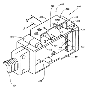
More specifically, FIGS. 7 and 7A illustrate an illustrative embodiment of the
invention in which an electrical junction block housing 400 (sometimes
referred to as the "junction
block") is supported on a structural member 402 by means of L-shaped mounting
lugs 404, 406 on
the housing 400. The lugs 404, 406 engage cooperating L-shaped brackets 408,
410 attached to the
structural member 402. The structural member 402 may, for example, be a metal
bracket attached to
an upper wall of a raceway in a wall panel or the like. Correspondingly, the
structural member 402
may, in fact, comprise part of a raceway upper wall itself. The junction block
housing 400 is
provided with a substantially horizontally-extending lower wall 414 and a
substantially parallel
upper wall 416. A vertical wall 418 (or a pair of vertical walls 418)
extending between the lower
414 and the upper wall 416 serves to divide a spacial area 420 from a similar
area on the opposite
side of the vertical wall 418. The spacial areas 420 are typically used to
accommodate electrical
outlet receptacle blocks or the like (not shown) in the junction block housing
400. The junction
block housing 400 may be connected to electrical outlet receptacle blocks or
the like by means of
electrical connectors 422 in a standard fashion. Correspondingly, as also
shown in FIG. 7, power
may be supplied to the junction block housing by means of an incoming power
cable 424.
The junction block housing 400 is maintained in a position relative to the
structural
member 402 by means of a retaining or "retainer" tab 426 mounted on the
structural member 402, or
otherwise formed integral therewith. As will described in subsequent
paragraphs herein, the retainer
tab 426 engages a latching device or latch assembly 428 disposed between the
mounting lugs 404,
14
CA 02605067 2007-10-04
WO 2006/116679 PCT/US2006/016240
14.0d coin J&::IL ~ wal'l-4"I 6:1"th:6 housing 400. In the particular
configuration shown herein, the L-
shaped brackets 408, 410 are actually formed integral with the horizontal
section 412 so as to form
the structural member 402. In addition, the retainer tab 426 is also formed as
an integral part of the
horizontal section 412 and L-shaped brackets 408, 410. Details of the
structural member 402 are
shown in the stand alone drawings of the same in FIGS. 12 and 13. The general
structural
interconnection of the structural member 402 to the junction block housing 400
is illustrated in the
exploded view of FIG. 7A.
The latch assembly 428 is illustrated in a number of the drawings, including
FIGS.
7A, 8 - 11 and 14 - 17. The latch assembly 428 is shown therein as comprising
a first cantilever
beam 430 and a second cantilever beam 432. The cantilever beams 430 and 432
are hinged to
opposing bottom portions of the structural member 402 at hinge points 434. The
hinge points 434
are preferably constructed of a resilient plastic material, which provides a
restoring force on the
cantilever beams 430, 432. The first cantilever beam 430 extends from its
hinge point 434 toward a
centerline of the housing 400, and is provided with a sloping center extension
436 which is shown
particularly in FIGS. 15 and 17. The center extension 436 extends beyond the
centerline and maybe
integral with the remaining portion of the first cantilever beam 430.
Correspondingly, the second
cantilever beam 432 also extends from its hinge point 434 toward a centerline
of the housing 400.
At the sides of the forwardmost surface of the second cantilever beam 432 are
a pair of opposing
lateral extensions 438. These extensions 438 are identified as a first lateral
extension 440 and a
second lateral extension 442. As with the remaining portion of the second
cantilever beam 432, the
lateral extensions 438 are also resilient and capable of deflection. The
lateral extensions 440 and
442 both extend from the second cantilever beam 432 beyond the centerline and
may be integral
with main portions of the second cantilever beam 432.
CA 02605067 2007-10-04
WO 2006/116679 PCT/US2006/016240
M--l'pritha it fsl bV 'n in FIGS. 8 - 11, the forward portions of the first
cantilever beam
430 and second cantilever beam 432 form a first ledge set 444.
Correspondingly, the first ledge set
444 and top surfaces 446 of the center extension 436 and lateral extensions
438 form a first channel
448. This channel 448 is illustrated in FIGS. 8 and 9, with the retainer tab
426 being engaged in the
first channel 448. As described in subsequent paragraphs herein, this
interlock position is
characterized as the "first interlocking position" for the retainer tab 426
and the latch assembly 428.
With further reference particularly to FIG. 10, the first cantilever beam 430
and
second cantilever beam 432 form, at their extended ends, a pair of ledge
surfaces 450. As further
shown in FIG. 10, these ledge surfaces 450, assuming that the first cantilever
beam 430 and second
cantilever beam 432 are in the positions illustrated in FIGS. 10 and 11, form
a second channel 452.
The operation of the latch assembly 428, with respect to interlocking of the
retainer
tab 426 of structural member 402, will now be described, primarily with
respect to FIGS. 7 - 17.
First, it will be assumed that the relative position of the junction block
housing 400 and the structural
member 402 is as shown in FIG. 7a. Further, it can be assumed that the
structural member 402, as
earlier described herein, is secured to a support plate at the top of a
raceway in an office panel, or
otherwise secured to the top of the raceway itself. With this stationary
configuration of the structural
member 402, it is further assumed that the retainer tab 426 has a length which
terminates at its lower
end as primarily shown in FIGS. 8 and 9. With reference first to FIG. 7a, when
the housing 400 is
moved toward the structural member 402, the L-shaped brackets 408, 410 will be
received within the
L-shaped mounting lugs 404, 406, respectively. Correspondingly, the lower edge
454 of the retainer
tab 426 will being to abut the sloping upper surface of the first cantilever
beam 430. This abutment
will cause the retainer tab 426 to exert a downward pressure on the upper
surface of the beam 430,
so as to cause the beam 430 to flex downwardly. This downward flexion will
continue to occur until
the lower edge 454 of the retainer tab 426 passes the ledge surface 450 of the
first cantilever 430.
16
CA 02605067 2007-10-04
WO 2006/116679 PCT/US2006/016240
i~it'h h 'lea iV?c6 ik 'r~ Cih ik"of the center extension 436 and the lateral
extensions 438, the beams
430 and 432 will form the first channel 448, with a width sufficient so that
the lower edge 454 of the
retainer tab 426 is captured within this first channel 448. This configuration
is illustrated in both
FIGS. 8 and 9.
In accordance with the foregoing description, the first channel 448 and the
relative
sizing of the retainer tab 426 and the beams 430, 432 are sufficient so as to
allow capture of the
retainer tab 426 of a particular length. However, as previously described
herein, one of the primary
concepts in accordance with the invention is that the latch assembly 428 is
constructed so as to allow
for a retainer tab which is longer in length, relative to the positioning of
the junction block housing
400. This relatively longer retainer tab 426 is illustrated in FIG. 10. More
specifically, with this
relatively longer retainer tab 426, when the retainer tab 426 passes over the
ledge surface 450 of the
first cantilever beam 430, the lower edge 454 will extend low enough so that
the beams 430 and 432
form the second channel 452. Correspondingly, with the relative length of the
retainer tab 426, the
lower edge 454 of the retainer tab 426 is captured within the second channel
452. In this manner,
the beams 430 and 432, with their center extension 436 and lateral extensions
438, cooperate so as to
capture the retainer tab 426 within the second channel 452.
In accordance with the foregoing, the latch assembly 428, also in accordance
with the
invention, can be characterized as a "two position" latch assembly, in that it
can capture retainer tabs
426 of different lengths, through the configurations which serve to form
either a first channel 448 or
a second channel 452. The channels 448, 452 are formed based upon the relative
length of the
retainer tab 426, and the position of the lower edge 454 of the retainer tab
426 relative to the
cantilever beams 430, 432.
To release or disengage the retainer tab 426 from the latch assembly 428, and
assuming that the retainer tab 426 is in the position shown in FIG. 8, or in
the position shown in FIG.
17
CA 02605067 2007-10-04
WO 2006/116679 PCT/US2006/016240
I 6; d1bvvn4 Rerted by a user on the upper surface of the first cantilever
beam
430, or the upper surface of the second cantilever beam 432. With the
interlocking engagement of
the cantilever beams 430, 432 as a result of the configurations of the center
extension 426 and the
lateral extensions 438, downward pressure exerted on either the first
cantilever beam 430 or the
second cantilever beam 432 will cause these beams 430, 432 to move downwardly,
up to the extent
illustrated in FIG. 11. This position can be characterized as the "full
release" position. With the
cantilever beams 430, 432 in the full release position, it is apparent from
FIG. 11 that the lower edge
454 of the retainer tab 426 is above the upper surfaces of the beams 430, 432.
Accordingly, the
junction block housing 400 can then be slid outwardly (in either direction)
from the structural
member 402. In this manner, the housing 400 can be removed from the attendant
raceway or the
like.
The configurations shown for the latch assembly 428 in accordance with the
invention permit the retainer tab 426 to be captured in either one of two
relative configurations of the
latch assembly 428. A first one of the configurations is illustrated in FIG.
8, while a second
configuration is illustrated in FIG. 10. From the remainder of the drawings
and the foregoing
description, it is shown and described that these configurations are provided,
in substantial part, by
the relative sizing and configurations of the center extension 436 and the
lateral extensions 438. As
shown, for example, in FIG. 17, the configurations are provided in part by the
center extension 436
associated with the first cantilever beam 430 overlapping the second
cantilever beam 432.
Correspondingly, the first lateral extension 440 and the second lateral
extension 442 associated with
the second cantilever beam 432 are made to overlap the first cantilever beam
430. It is this
configuration and the relative sizing of the beams 430, 432 which permit the
"two position"
configuration for the latch assembly 428 and the retainer tab 426.
18
CA 02605067 2012-08-27
It will be apparent to those skilled in the pertinent arts that still other
embodiments of
latch assemblies in accordance with the invention can be designed. That is,
the principles of a
latch assembly in accordance with the invention are not limited to the
specific embodiments
described herein. The scope of the claims should not be limited by particular
embodiments
set forth herein, but should be construed in a manner consistent with the
description as a
whole.
19