Note: Descriptions are shown in the official language in which they were submitted.
CA 02605087 2007-10-04
WO 2006/130317 PCT/US2006/017984
ENDOPROSTHESES
TECHNICAL FIELD
The invention relates to medical devices, such as endoprostheses (e.g.,
stents).
BACKGROUND
The body includes various passageways such as arteries, other blood vessels,
and
other body luinens. These passageways soinetimes become occluded or weakened.
For
example, the passageways can be occluded by a tumor, restricted by plaque, or
wealcened
by an aneurysm. When this occurs, the passageway can be reopened or
reinforced, or
even replaced, with a medical endoprosthesis. An endoprosthesis is typically a
tubular
member that is placed in a lumen in the body. Examples of endoprostheses
include
stents, covered stents, and stent-grafts.
Endoprostheses can be delivered inside the body by a catheter that supports
the
endoprosthesis in a coinpacted or reduced-size form as the endoprosthesis is
transported
to a desired site. Upon reacliing the site, the endoprosthesis is expanded,
for example, so
that it can contact the walls of the lumen.
The expansion mechanism may include forcing the endoprosthesis to expand
radially. For example, the expansion mechanism can include the catheter
carrying a
balloon, which carries a balloon-expandable endoprosthesis. The balloon can be
inflated
to deform and to fix the expanded endoprosthesis at a predetermined position
in contact
with the lumen wall. The balloon can then be deflated, and the catheter
withdrawn.
In another delivery technique, the endoprosthesis is formed of an elastic
material
that can be reversibly compacted and expanded, e.g., elastically or through a
material
phase transition. During introduction into the body, the endoprosthesis is
restrained in a
compacted condition. Upon reaching the desired implantation site, the
restraint is
removed, for example, by retracting a restraining device such as an outer
sheath, enabling
the endoprosthesis to self-expand by its own inteinal elastic restoring force.
When the endoprosthesis is advanced through the body, its progress can be
monitored, e.g., tracked, so that the endoprosthesis can be delivered properly
to a target
site. After the endoprosthesis is delivered to the target site, the
endoprosthesis can be
monitored to determine whether it has been placed properly and/or is
functioning
properly. The lumen in which the endoprosthesis is placed can also be
monitored to
-1-
CA 02605087 2007-10-04
WO 2006/130317 PCT/US2006/017984
detennine whether it has renarrowed. Methods of monitoring include X-ray
fluoroscopy,
magnetic resonance imaging (MRI), and computed tomography (CT).
In computed tomography, a CT scanner is used to construct two- and three-
dimensional images from inultiple scans. The CT scarmer has an X-ray source
mounted
on a circular track, and an arc-shaped detector also mounted on the traclc and
opposite to
the X-ray source. During use, the patient is positioned such that the track
surrounds the
patient. The X-ray source and the detector are then moved along the track,
while the X-
ray source emits an X-ray beam at multiple angles, and the detector detects
the X-rays
trarismitted through the patient and the endoprosthesis. The X-rays detected
by the
detector are then sent to a computer for processing and forming the desired
two- and
tluee-dimensional images for display.
SUMMARY
The invention relates to medical devices, such as endoprostheses.
h-1 one aspect, the invention features an endoprosthesis having a tubular body
including a first material and a second material. The first material has a
first mass
attenuation coefficient and the second material has a second mass attenuation
coefficient
greater than the first mass attenuation coefficient. The second material is on
greater than
zero to 50% of a circumferential cross section defined by the body.
Embodiments may include one or more of the following features. The second
material can be on greater than zero to forty percent of any circumferential
cross section
defined by the body. The body can have a pattern of cells defined by bands,
where at
least one of the cells comprises one or more bands surrounding an aperture and
at least
one of the cells comprises one or more bands surrounding a solid area and
forins a solid
cell including the first material; the second material can contact at least a
portion of the
solid cell. The second material can be on less than or equal to about twenty
percent of
any circumferential cross section defined by the body. The second material can
be on less
than or equal to about one eighth of any circumferential cross section defined
by the
body. The second material can be substantially non-biodegradable. The second
material
can be located at one or both ends of the body. A cross-sectional portion
between the
ends of the body can be free of the second material. The second material can
be located
along a length of the body. The second material can be located at a series of
discontinuous portions along a lengtlz of the body. The second material can
extend
-2-
CA 02605087 2007-10-04
WO 2006/130317 PCT/US2006/017984
spirally along the body. At least a portion of the second material can be at
least about
five microns thiclc. The second material can have a density greater than about
9.9 g/cm3:
The second material can be fonned as two separate portions, each portion on
opposing
circumferential areas of the body. The second material can be selected from
the group
consisting of tantalum, titanium, zirconium, iridium, palladiuin, hafiiium,
tungsten, gold,
rtiitheniuin, rheniuin, bariuin, dysprosium, gadoliniusn and platinum. The
second material
can include an alloy. The endoprostllesis can include a drug. The second
material can be
disposed outwardly relative to the body. A biodegradable coating can be on the
body, the
biodegradable coating comprising a third material having a third mass
attenuation
lo coefficient higher than the first mass attenuation coefficient.
In yet another aspect, the invention features a method including obtaining an
image of an endoprosthesis in a body using computed tomography, the
endoprosthesis
comprising a tubular body including a first material having a first mass
attenuation
coefficient, and a second material on less than or equal to half of a
circuinferential cross
section defined by the body, the second material having a second mass
attenuation
coefficient greater than the first mass attenuation coefficient.
Einbodiments of the method may include one or more of the following features.
Obtaining the image can include detennining a first and a second set of images
from a
plurality of computed tomography scan images, wherein the first set of images
display a
2o higher percentage of the second material than the second set of images. The
method can
include fonning a final image fiom the second set of images. The determining
step can
detennine a set of images that display less than a predetermined a.inount of
the second
material.
In yet another aspect, the invention features a method including obtaining a
plurality of computed tomography scan images of a body having the
endoprosthesis
located tllerein. Images that display the endoprosthesis are determined from
the plurality
of coinputed tomography scan images. Selected images that display the
endoprosthesis
are subtracted from the plurality of computed tomography scans to determine a
set of
desired images. The selected images can display a higher percentage of the
coating than a
second set of images. A final image is fonned from the desired images.
In another aspect, the invention features an implantable filter having a
plurality of
elongated members having a first material with a first mass attenuation
coefficient, at
least one elongated member having a second material with a second mass
attenuation
-3-
CA 02605087 2007-10-04
WO 2006/130317 PCT/US2006/017984
coefficient higher than the first mass attenuation coefficient, and at least
one elongated
member being free of the second material.
Embodiments may include one or more of the following advantages. A stent
partially coated with radiopaque material allows a physician the freedom to
use a wider
range of imaging techniques for observation and diagnosis. Both fluoroscopic
imaging
and CT imaging can be useful to the physician for different purposes and at
different
times of treating or monitoring a patient. A stent that is viewable using
either imaging
,
techniques provides greater flexibility to a physician wanting to monitor the
patient's
health or to diagnose disease. In comparison, certain stents may not be fully
compatible
1 o with CT imaging, because the X-ray attenuation or radiopacity of materials
used in the
stents may be too high for CT imaging. For example, images of stents fully
coated with
radiopaque material obtained by CT angiography can produce blooming artifacts
and
artificial thickening of the stent components that are displayed. These
effects can lead to
image artifacts that interfere with lumen visualization and quantification.
Ot11er aspects, features, and advantages will be apparent from the description
of
the preferred embodiments tllereof and from the claims.
DESCRIPTION OF DRAWINGS
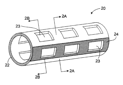
Fig. 1 is a perspective view of an einbodiinent of an expanded stent; Fig. 2A
is a
cross section of the stent of Fig. 1, taken along line 2A-2A; and Fig. 2B is a
cross section
of the stent of Fig. 1, taken along line 2B-2B.
Fig. 3 is a diagrammatic view of a stent during a computed tomography
procedure.
Fig. 4 is cross section of a stent with two coating portions.
Fig. 5 is a diagrammatic view of a stent with two coating portions during a
computed tomography procedure.
Figs. 6, 7 and 8 are perspective views of embodiments of expanded stents.
Figs. 9 and 10 are side views of embodiinents of expanded stents.
Fig. 11 is a flow chart of an embodiment of a method of forming a stent.
Fig. 12 is a flow chart of an embodiment of a method of imaging a stent.
Fig. 13 is a schematic of fluoroscopic imaging of a body with a stent embedded
therein.
-4-
CA 02605087 2007-10-04
WO 2006/130317 PCT/US2006/017984
Fig. 14 is a schematic of computed tomography imaging of a body with a stent
einbedded therein.
Fig. 15 is a perspective view of an embodiment of a stent.
Fig. 16 is a cross section of an embodiment of a stent.
DETAILED DESCRIPTION
Referring to Figs. 1, 2A and 2B, a stent 20 includes a tubular body 22 having
a
plurality of openings 23, and a coating 24 on a portion of the tubular body.
Tubular body
22 can be made of a biocoinpatible material with mechanical properties that
allow stent
20 to be compacted and subsequently expanded to support a vessel, such as
stainless steel,
magnesiuin alloy or a nickel-titanium alloy. Coating 24 can be made of a
radiopaque
material, such as platinuin or gold. Along one or more circumferential cross
sections of
stent 20, coating 24 covers less than or equal to 50% of the circumference
occupied by
tubular body 22. For example, as shown in Fig. 2A, coating 24 covers less than
25% of
the circumference occupied by tubular body 22.
Coating 24 is capable of enlzancing the visibility of stent 20 under X-ray
visualization tecluziques, such as fluoroscopy, and particularly under
computed
tomography (CT). Referring to Fig. 3, stent 20 is shown in a CT scanner having
an X-ray
source 410 mounted on a circular track 502. During a computed tomography
procedure,
X-ray source 410 moves along track 502 and emits X-rays 520, 540 while a
detector (not
shown) mounted on the track opposite the X-ray source 410 detects X-rays
transmitted
througlz the implanted stent 20. Scans from different angles are taken along
track 502 to
generate the desired images to be displayed. As shown in Fig. 3, at point 510,
the cross
section of the stent that is intersected by X-rays 520 and that is relatively
radiopaque is
small, and most of the X-rays 520 pass through the relatively radiolucent
tubular body 22
of the stent. That is, at point 510, X-rays 520 produce an image with
relatively little of
radiopaque coating 24. In comparison, at point 530, many of the X-rays 540
impinge
upon radiopaque coating 24 to produce an image with a higher amount of the
radiopaque
coating 24. The images produced froin point 530 indeed can be too highly
visible (e.g.,
3o bright) and obscure visualization of the stent 20, the vessel in which the
stent 20 is placed,
and the surrounding tissue. But by collecting the desired images from
different points
along track 502, eliminating those images that are too radiopaque (e.g., at
point 530), and
keeping images that are less radiopaque, more usefiul images can be
constructed and
-5-
CA 02605087 2007-10-04
WO 2006/130317 PCT/US2006/017984
displayed. In comparison, stents that are fi.illy coated with radiopaque
material do not
offer the option of eliminating CT images that are too highly visible because
the levels of
X-ray attenuation are relatively uniform about the circumference of the stent.
During a
CT procedure, the fully coated stents may show blooming artifacts or
artificial thickening
of the stent structure that impede visualization and quantification of the
vessel lumen.
Referring again to Fig. 1, tubular body 22 can include (e.g., be manufactured
from) one or more biocompatible materials with mechanical properties so that
stent 20
can be compacted, and subsequently expanded. In some embodiments, stent 20 can
have
an ultimate tensile strength (UTS) of about 20-150 kPSI, greater than about
15%
elongation to failure, and a modulus of elasticity of about 10-60 MPSI. When
stent 20 is
expanded, the material can be stretched to strains on the order of about 0.3.
Examples of
"structural" materials that provide good mechanical properties (e.g.,
sufficient to support
a lumen wall) and/or biocoinpatibility include, for example, stainless steel
(e.g., 316L and
304L stainless steel, and PERSS ), Nitinol (a nickel-titanium alloy), Elgiloy,
L605
alloys, MP35N, Ti-6A1-4V, Ti-50Ta, Ti-lOlr, Nb-lZr, Ti-4Al-4Mo-4Sn-0.5Si (551)
and
Co-28Cr-6Mo. Because of its low radiopacity, a magnesiutn alloy with a
corrosion
resistant surface treatment or a corrosion resistant magnesium alloy can also
be used.
Other materials inch.ide elastic biocompatible metal such as a superelastic or
pseudo-
elastic metal alloy, as described, for example, in Schetsky, L. McDonald,
"Shape Memory
2o Alloys", Encyclopedia of Chemical Technology (3rd ed.), John Wiley & Sons,
1982, vol.
20. pp. 726-736; and commonly assigned, Stinson, US 2004/0143317 Al. Tubular
body
22 can include (e.g., be fonned of) a biodegradable metal or a polymer (e.g.,
a
biodegradable polymer), as described in Bolz, U.S. 6,287,332; Heublein, US
2002/0004060 Al; U.S. 5,587,507; and U.S. 6,475,477. Tubular body 22 can
include two
or more layers, for example of different compositions. In some einbodiments,
the
material(s) of tubular body 22 is less radiopaque or more radiolucent than the
material(s)
of coating 24.
Coating 24 can be made of one or more biocompatible materials capable of
en.hancing the radiopacity of body 22, for example, by having a higher density
or mass
attenuation coefficient. Examples of radiopaque materials include metallic
elements
having atomic numbers greater than 26, e.g., greater than 43. In some
einbodiments, the
radiopaque materials have a density greater than about 9.9 g/cc. In certain
embodiments,
the radiopaque material is relatively absorptive of X-rays, e.g., having a
linear attenuation
coefficient of at least 25 cm-1, e.g., at least 50 cni 1, at 100 keV. Some
radiopaque
-6-
CA 02605087 2007-10-04
WO 2006/130317 PCT/US2006/017984
materials include tantalum, platinum, iriditun, palladium, hafnium, zirconium,
tungsten,
molybdenum, gold, ruthenium, bismuth, and rheniuin. Oxides of radiopaque
materials,
such as bismutli oxide and zirconium oxide, can be used. The radiopaque
material can
include an alloy, such as a binary, a ternary or more coinplex alloy,
containing one or
more elements listed above with one or more other elements such as iron,
nickel, cobalt,
or titanium. Examples of alloys including one or more radiopaque materials are
described
in U.S. Application Publication US-2003-0018380-Al; US-2002-0144757-Al; and US-
2003-0077200-Al. Coinbinations of any of the above materials can also be used.
In some embodiments, coating 24 includes one or more organic components and
one or more of the radiopaque materials described above. The organic
component(s) can
include a biocompatible polymer that is biodegradable or non-biodegradable.
Examples
of polymers include polytetrafluoroethylene (PTFE), expanded PTFE,
polyethylene,
urethane, or polypropylene. Examples of biodegradable polymers are described
in U.S.
5,587,507; and U.S. 6,475,477.
Referring to Fig. 4, in some implementations, the coating 24 is applied to two
portions of the stent, where the two portions are substantially opposite along
the
circumference of the stent. As shown in Fig. 5, the X-rays 540 passing tluough
the
radiopaque coating 24 of the stent pass tlirough both coatings when the
coatings are
opposite to one another.
As indicated above, coating 24 covers less than or equal to 50%, such as less
than
about 20%, of a circumference occupied by tubular body 22. The circumference
occupied by tubular body 22 can be equal to or less than the circumference
generally
defined by the tubular body. For example, in the cross section shown in Fig.
2A, the
circumference occupied by tubular body 22 is equal to the circumference
defined by the
tubular body, which is measured along the exterior surface of the tubular
body. But at the
cross section shown in Fig. 2B, which intersects openings 23, the
circumference occupied
by the tubular body is equal to the circumference defined by the tubular body
at that cross
section, ininus the circumference defined by the openings. Other einbodiments
of stents
in which the circumference occupied by the tubular body is less than the
circuinference
3o defined by the tubular body include stents formed by lcnitting or weaving
wires, and
stents having bands connected by com.iectors (as shown below in Figs. 9 and
10).
Coating 24 can cover greater than or equal to zero percent, about 5%, about
10%, about
15%, about 20%, about 25%, about 30%, about 35%, about 40%, or about 45% of a
circuinference occupied by tubular body 22; and/or less than or equal to 50%,
about 45%,
-7-
CA 02605087 2007-10-04
WO 2006/130317 PCT/US2006/017984
about 40%, about 35%, about 30%, about 25%, about 20%, about 15%, about 10%,
or
about 5% of a circumference defined by the tubular body. The degree to which
coating
24 extends along a circumference of a stent can vary or be constant along the
length of
the stent (Fig. 6).
The thickness of coating 24 can also vary, and can be dependent, for exainple,
on
the type of stent, the material and or/ thickness from which the body 22 is
formed, the
degree to which the coating covers the stent, and the composition of the
coating. In some
embodiments, the thicluzess of coating 24 is at least about five microns
thick. In one
embodiment, a stent that is about 80 microns thick and formed of magnesium
having a
1 o partial coating of gold that is at least about 8 microns thick is
sufficiently visible to under
fluoroscopy. The thiclmess can be determined by the mass attenuation
coefficient of the
material used to form the coating. As an example of the coating thickn.ess,
the coating 24
(or stent 20 with the coating 24) can be formed to be sufficiently thick to be
as radiopaque
as a stainless steel stent having a strut thiclrness of about 80 microns,
which is sufficient
radiopaque to 80keV fluoroscopy X-rays. The mass attenuation coefficient of
the coating
24 plus any material under the coating, such as the tubular body 22, can be
used to
determine how thick the coating needs be for the stent 20 to have radiopaque
portions.
Changing the materials, the X-ray voltage or thiclclless of the body 22 can
change the
required thickness of the coating 24. Coating compositions having high density
materials
or high atomic numbers may be thinner than materials having low density or low
atomic
numbers. Stents with high coating coverage may be thinner than low coating
coverage.
The thiclc-iess of coating 24 can vary along a stent.
Coating 24 can be formed anywhere along an axial direction of stent 20. For
example, coating 24 can be on the exterior surface of stent 20 and/or on the
interior
surface of the stent. In embodiments in which tubular body 22 includes
multiple layers,
coating 24 can be between two or more layers of the tubular body. More than
one coating
can be formed along an axial direction. For example, along an axial direction,
a stent
may inch.ide a radiopaque coating on the exterior surface and one or more
coatings
between the exterior surface and the interior surface.
The mamier in which coating 24 extends along stent 20 can also vary. For
example, as shown in Fig. 1, coating 24 can extend generally linearly and
uninterruptedly
from one end of the stent to the otller end. hi other einbodilnents; referring
to Fig. 7,
coating 24 extends non-linearly, as shown, spirally, about the stent. Coating
24 can also
extend discontinuously along the length of the stent such that two or more
areas of
- 8 -
CA 02605087 2007-10-04
WO 2006/130317 PCT/US2006/017984
coating 24 are separated by one or more portions of uncoated stent. For
example, Fig. 8
shows stent 20 with both ends having coating 24 of radiopaque material.
Coating stent 20
at one or both ends can enable the ends of stent 20 to be detected. If
determining the
position of the end of stent 20 is desired, such as when inultiple stents are
aligned in a
row, coating the ends cail increase the visibility of the ends of stent 20.
Coating 24 can
extend along less than the entire length of a stent. For exainple, coating 24
can be located
only at end portions (as shown in Fig. 8) or the coating can be located only
one or more
portions between the end portions.
Still other einbodiments of coated stents can be formed. Fig. 9 shows stent 20
in
1 o the form of a tubular member defined by a plurality of bands 42 and
connectors 44 that
extend between and connect adjacent bands. Bands 42 and coiuzectors 44 define
the
perimeter of a cell 46. Each ce1146 can be an open cell, that is, bands 22 and
comzectors
24 surround an aperture; or each cel146 can be a closed cell, for example, the
cell can
have a solid surface made of a stent material. In some einbodiments, most of
the cells 46
are open cells. To the closed cells, coating 24 can be applied. As shown in
Fig. 9, cells
having a coating 24 can be adjacent to one another. Alternatively, one or more
non-
coated cells can be between cells having coating 24. When cells 46 are coated,
a whole
cell can be coated with radiopaque material, or only a portion of ce1146 can
be coated.
Referring to Fig. 10, coating 24 can be applied such that the coating does not
completely
correspond to one or more cells, but covers a portion of stent cells.
Fig. 11 shows a method 100 of making stent 20. As shown, method 100 includes
forming a tube (step 102) that makes up tubular body 22 of stent 20. The tube
is
subsequently cut to foim openings (or bands 22 and connectors 24) (step 104)
to produce
an unfinished stent. Areas of the unfinished stent affected by the cutting are
subsequently
removed (step 106). The unfinished stent is finished (step 108). One or more
portions of
stent 20 is coated with a radiopaque material (step 110), and the stent can
then be fiirther
finished.
The tube that makes up the tubular meinber of stent 20 can be formed using
metallurgical techniques, such as thermomechanical processes (step 102). For
example, a
3o hollow metallic member (e.g., a rod or a bar) can be drawn through a series
of dies with
progressively smaller circular openings to plastically defonn the member to a
targeted
size and shape. In some embodiments, the plastic deformation strain hardens
the ineinber
(and increases its yield strength) and elongates the grains along the
longitudinal axis of
the member. The deformed member can be heat treated (e.g., annealed above the
-9-
CA 02605087 2007-10-04
WO 2006/130317 PCT/US2006/017984
recrystallization temperature and/or hot isostatically pressed) to transform
the elongated
grain structure into an initial grain structure, e.g., one including equiaxed
grains. Small or
fine grains can be fonned by heating the member close to the recrystallization
teinperature for a short time. Large or coarse grains can be fonned by heating
the
member at higher temperatures and/or for longer times to promote grain growth.
Next, openings (or bands 22 and connectors 24) of stent 20 are formed, as
shown,
by cutting the tube (step 104). Selected portions of the tube ca.n be removed
to form
bands 22 and connectors 24 by laser cutting, as described in U.S. Patent No.
5,780,807,
hereby incorporated by reference in its entirety. In certain embodiments,
during laser
cutting, a liquid carrier, such as a solvent or an oil, is flowed through the
lumen of the
tube. The caiTier can prevent dross fonned on one portion of the tube from re-
depositing
on another portion, and/or reduce formation of recast material on the tube.
Otlier methods
of removing portions of the tube can be used, such as mechanical machining
(e.g., micro-
machining), electrical discharge machining (EDM), and photoetcliing (e.g.,
acid
photoetching).
hi some embodiments, after bands 22 and connectors 24 are formed, areas of the
tube affected by the cutting operation above can be removed (step 106). For
example,
laser machining of bands 22 and connectors 24 can leave a surface layer of
melted and
resolidified material and/or oxidized metal that can adversely affect the
mechanical
properties and performance of stent 20. The affected areas can be reinoved
mechanically
(such as by grit blasting or honing) and/or chemically (such as by etching or
electropolishing).
The unfinished stent is then finished (step 108). The unfinished stent can be
finished, for exainple, by chemical milling and/or electropolishing to a
smooth finish.
Coating 24 of radiopaque material is then applied to one or more selected
portions
of the stent (step 110). The radiopaque material can be deposited, for
example, using
cheinical vapor deposition, sputtering, physical vapor deposition, and/or
laser pulse vapor
deposition. A inandrel can be placed inside of the stent to prevent the
radiopaque
material fiom being applied to portions of the stent other than where the
material is
so desired. A mask can be placed between the stent and the source of the
radiopaque
material to control the area of the stent to which the material is applied.
Other coating
methods can also be used, such as maslcing the portions of the stent which are
not to be
coated and dipping the stent in radiopaque material. A coating, such as a drug-
eluting
polyiner coating, can be coated onto a portion of the stent and radiopaque
particles can be
-10-
CA 02605087 2007-10-04
WO 2006/130317 PCT/US2006/017984
mechanically pressed into the polyiner coating. In one embodiment, the
polyiner can be
made tacky so that the particles stick to the coating. Alternatively,
radiopaque particles
can be attaclled to stent 20 with an adhesive coating.
Stent 20 can be foimed of a desired shape and size (e.g., coronary stents,
aortic
stents, peripheral vascular stents, gastrointestiiial stents, urology stents,
and neurology
stents). Depending on the application, stent 20 can have a diaineter of
between, for
exaa.nple, 1 mm to 46 mm. In certain embodiments, a coronary stent caal have
an
expanded diameter of from about 2 mm to about 6 mm. In some embodiments, a
peripheral stent can have an expanded diameter of from about 5 mm to about 24
mm. In
certain embodiments, a gastrointestinal and/or urology stent can have an
expanded
diaineter of from about 6 mm to'about 30 mm. In some einbodiments, a neurology
stent
can have an expanded diameter of from about 1 mm to about 12 mm. An abdominal
aortic aneurysin (AAA) stent and a thoracic aortic aneurysm (TAA) stent can
have a
diameter from about 20 mm to about 46 inm. Stent 20 can be balloon-expandable,
self-
expandable, or a combination of both (e.g., as described in U.S. Patent No.
5,366,504).
In use, stent 20 can be used, e.g., delivered and expanded, using a catheter
delivery system (step 202). Catheter systeins are described in, for example,
Wang U.S.
5,195,969, Hamlin U.S. 5,270,086, and Raeder-Devens, U.S. 6,726,712. Stents
and stent
delivery are also exemplified by the RadiusOO or Symbiot@ systems, available
from
2o Boston Scientific Scimed, Maple Grove, MN.
During and/or after stent delivery, stent 20 can be imaged using X-ray
fluoroscopy
and/or computed axial tomograplly. Fig. 12 shows an illustrative method 200
that
includes using multiple methods to image stent 20 in a lumen. First, stent 20
is inserted
into a body, such as into a lumen, for example, an artery (step 202). During
delivery, X-
ray fluoroscopy can be used to image stent 20 witliin the body by focusing X-
rays on the
body in the vicinity of the location of stent 20, detecting the X-rays that
have passed
through the body, and displaying an image on a monitor (step 204).
Altematively or
additionally, stent 20 can be monitored in the body by capturing a group of
images with a
computed axial tomography (CAT or CT) device (step 206). Of the iinages that
are
captured by the CT scans, some of the images display a substantial amount of
radiopaque
coating 24, while other images display less than a threshold ainount of the
radiopaque
coating (e.g., relatively little to virtually none of the radiopaque coating
24). The images
that display less than a threshold ainount of radiopaque coating 24 of stent
20 are
determined (step 208). A final display image is built from the images that
show less than
-11-
CA 02605087 2007-10-04
WO 2006/130317 PCT/US2006/017984
a threshold amount of radiopaque coating 24 (step 210). h-i other
einbodiments, only one
imaging technique, such as CT, is used during and after stent delivery.
Referring also to Fig. 13, stent 20 can be viewed in the body using X-ray
fluoroscopy (step 204). During fluoroscopy, an X-ray source 310 emits X-rays
that are
directed through body 300. An X-ray detector 320 detects the X-rays after the
X-rays
have passed througll the body 300 and stent 20 to capture signals. The signals
are then
sent to a display 330, such as a monitor or computer soreen, which displays a
corresponding image.
Referring to Figs. 3 and 14, stent 20 can also be viewed in the body using a
CT
1 o scam7er (step 206). The CT scanner is used to construct two- and tliree-
dimensional
images from multiple images. The CT scanner has a rotating gantry with an X-
ray source
410, such as an X-ray tube, mounted on one side and an arc-shaped detector
mounted on
the opposite side. The X-ray source moves along a circular traclc 502,
starting at point
500 and moving toward point 510 and 530. The X-ray source emits an X-ray beam
in a
fan shape as the X-ray source and detector are rotated around body 300. At
various
points along the track 502, images are obtained. Approximately 1000 images may
be
obtained for each rotation of the X-ray source. Images are obtained up and
down at least
a portion of body 300. The images are obtained wlien the X-ray source 410
emits X-rays
through body 300. An X-ray detector 420 detects the X-rays after they have
passed
through the body 300. The images are sent to aycomputer 430.
As the X-ray source 410 moves around body 300, images from different angles of
body 300 and stent 20 are captured. At point 510, most of X-rays 520 pass
through a
portion of stent 20 that is includes tubular body 22, which is relatively
radiolucent. At
point 510, X-rays 520 emitted from X-ray source 410 produce relatively few
images that
show radiopaque coating 24. In comparison, at point 530, many of the X-rays
impinge
upon radiopaque coating 24 of stent 20 to produce images of the radiopaque
coating. Of
course, additional images can be captured at other points along traclc 502 and
beyond, and
Fig. 3 shows only points 510 and 530 for simplicity and clarity.
To improve the final image obtained by CT device, the initial images captured
by
the CT scanner can be examined to determine which of the images display more
than a
threshold ainount of radiopaque coating 24 and which of the images display
less than a
threshold ainount of the radiopaque coating (step 208). The images that
display more
thaiz a threshold amount of radiopaque coating 24 may produce blooming
artifacts and/or
artificial thickening of the components of stent 20, and can be ignored in
forming the
-12-
CA 02605087 2007-10-04
WO 2006/130317 PCT/US2006/017984
image that is displayed. For example, the images captured at point 530 show
much more
of the radiopaque material than the images captured at point 510. Images
obtained at
points that display less than a threshold amount of radiopaque coating 24,
such as at point
510, are selected for calculating the displayed image.
In some implementations, to determine the threshold amount of radiopaque
coating 24, images are obtained at all points around the body. All the data
points are used
to deteiznine the location of the stent in the body. Using the images that
show the stent,
images from a fraction of the circle are calculated. For exainple, if the
stent is designed
so that 50% of the images are usable, the data from a first portion of the
images, such as
1 o the images obtained between 0 to 90 , can be calculated. Then, data from a
second
portion, for example, where the second portion is 10 offset from the first
portion (images
obtained between 10 to 100 ), is calculated. The calculations are repeated
until images
from around 180 of the stent are calculated, because the other half of the
stent is
syinmetric to the first half. The least absorbing set of images are then
selected. The step
size, described above as being 10 , can be fine tuned, such as to 5 . Thus, if
the set of
images between 40-130 is the best set of images, the calculation can be fine
tuned
between 35-125 and 45-135 .
From the images that display less than a threshold amount of radiopaque
coating
24, a display image is formed (step 210). Building the final image can include
compositing the individual images to obtain the final two- or tlhree-
dimensional image or
images.
While a nuinber of embodiments have been described above, the invention is not
so limited.
For exainple, referring to Fig. 15, a stent may include one or more portions
25 in
which radiopaque coating 24 extends more than 50% of the circumference of the
stent,
for exainple, coinpletely around the circuinference. The portion(s) of coating
24 that
extends more than 50% of the circumference of the stent can enhance visibility
during
fluoroscopy, while portion(s) of the coating that extends less than or equal
to 50% of the
circumference of the stent can enhance visibility during CT.
In some embodiments, stent 20 includes a releasable therapeutic agent, drug,
or a
pharmaceutically active compound. The agent, drug, or coinpound can be
incorporated in
radiopaque coating 24 (e.g., a polyineric radiopaque coating) and/or as a
separate coating.
Exainples of releasable therapeutic agents, drugs, or a pharmaceutically
active
coinpounds are described in U.S. Patent No. 5,674,242, Z11ong, US 2003/003220
Al, and
-13-
CA 02605087 2007-10-04
WO 2006/130317 PCT/US2006/017984
Lanphere US 2003/0185895 Al. The therapeutic agents, drugs, or
pharmaceutically
active coinpounds can include, for example, anti-thrombogenic agents,
antioxidants, anti-
inflaimnatory agents, anesthetic agents, anti-coagulants, and antibiotics.
Stent 20 can be a part of a covered stent or a stent-graft. In other
einbodiments,
stent 20 can include and/or be attached to a biocompatible, non-porous or semi-
porous
polymer matrix made of polytetrafluoroethylene (PTFE), expanded PTFE,
polyethylene,
urethane, or polypropylene.
In some embodiments, in addition to coating 24, a stent includes a radiopaque,
bioabsorbable coating. Referring to Fig. 16, stent 20 can include radiopaque
coating 24
extending about a portion of the circumference of the stent, and a radiopaque,
bioabsorbable coating 25 that extends about the remaining portion of the
circumference of
the stent. Coating 25 is capable of enhancing the radiopacity of stent 20, for
example,
under fluoroscopy during stent delivery. After the stent has been iinplanted,
coating 25
can be bioabsorbed, thereby leaving coating 24 to enhance visibility during
CT. Coating
25 can include a bioabsorbable polymer and a radiopaque material, as described
above.
In some embodiments, coating 25 only covers a portion of the circumference of
the stent
not covered by coating 24.
The radiopaque coatings described herein can be applied to otlzer medical
devices,
such as filters. A filter can include a porous portion for filtering and a
struts for
supporting the porous portion. One or more of the struts can be fiilly or
partially coated
with radiopaque material.
In some embodiments, stent 20 includes one or more materials that enhance
visibility by magnetic resonance imaging (MRI). Examples of MRI materials
include
non-ferrous metal-alloys containing paramagnetic elements (e.g., dysprosium or
gadoliniuin) such as terbium-dysprosium, dysprosium, and gadolinium; non-
ferrous
metallic bands coated with an oxide or a carbide layer of dysprosium or
gadolinium (e.g.,
Dy203 or Gd203); non-ferrous metals (e.g., copper, silver, platinuin, or gold)
coated with
a layer of superparamagnetic material, such as nanocrystalline Fe304, CoFeZO4,
MnFe2O4,
or MgFeZO4i and nanocrystalline particles of the transition metal oxides
(e.g., oxides of
3o Fe, Co, Ni). Alteniatively or in addition, stent 20 cal include one or more
materials
having low magnetic susceptibility to reduce rnagnetic susceptibility
artifacts, which
duriulg imaging can interfere with imaging of tissue, e.g., adjacent to and/or
surrounding
the stent. Low magnetic susceptibility materials include tantalum, platinum,
titanium,
niobium, copper, and alloys containing these elements. The MRI visible
materials can be
-14-
CA 02605087 2007-10-04
WO 2006/130317 PCT/US2006/017984
incorporated into the structural material, can serve as the structural
material, and/or be
included as one or more layers of stent 20.
All publications, references, applications, and patents referred to herein are
incorporated by reference in their entirety.
Other embodiments are within the claims.
-15-