Note: Descriptions are shown in the official language in which they were submitted.
CA 02605260 2007-11-01
LOCKABLE SWIVEL APPARATUS AND METHOD
Description
This application is a division of Canadian Patent Application
Serial No. 2276517, filed 27 December 1997, as the Canadian national
phase application corresponding to International Application No.
PCT/US97/24043.
Technical Tiefd
The present invention relates generally to a drill
string apparatus for use in drilling operations, and more
particularly to an apparatus and method for selectively
locking an inline swivel to permit rotational movement of
the drill string.
Background Art
In wireline operations, it is often desirable to
selectively allow the drill string to rotate freely while
the wireline operator manipulates the wireline. The
invention disclosed herein provides, an apparatus which
,would allow the connection of various wireline devices to
be placed in the drill string between the top drive unit
and the rotary table of a conventional drilling rig
throughout wireline operations. Such devices as the Boyd
Borehole Drill Pipe Continuous Side Entry Or Exit Apparatus
(such as described in U. S. Reissue Patent No. 33,150) or
applicant's Top Entry Sub Arrangement (as described in U.
S. Patent No. 5,284,210) may both be utilized for various
wireline operations. ,
Previously, if the operator desired to rotate the
drill string during wireline operations, the wireline was
CA 02605260 2007-11-01
2 -
pulled from the well bore and the entry devices were
disengaged from the drill string. The removal of the
wireline could be avoided if an inline swivel was placed in
the drill string between the wireline device and the rotary
table. This arrangement would permit rotation to be
accomplished with a wireline in place, but effectively
disengaged the top-drive unit from its preferred role of
providing both lifting power and rotation to the drill
string.
Disclosure of Invention
The invention is a lockable in-line swivel device
which is selectively engaged by the operator to permit or
inhibit rotational movement provided by a top drive unit to
be transmitted through the swivel to the drill string and
to allow disengagement of the locked swivel so that
rotation may be accomplished by the rotary table
simultaneously with the wireline operations.
Accordingly, it is the primary purpose of the
invention disclosed herein to provide an apparatus and
method which permits the wireline entry devices described
above to be left in the drill string during all operations
involving the wireline:operation. This avoids the time
consuming makeup and disengagement of the entry tools
required to safely permit entry of the wireline into the
well bore. If rotation and longitudinal movement is
desired with the invention disclosed herein, the wireline
alone is removed from the wellbore, but the entry tool
remains in place and the swivel is locked to provide
CA 02605260 2007-11-01
ti 1 - )
- 3 -
transmission of all rotation through the swivel into the
drill string.
At other times, the operator using a top-drive unit may
desire to pick up the drill string and yet maintain torque
which has been put into the drill string in pipe recovery
operations. This is best done by engaging the swivel in
locked position and picking up with the top drive unit. As
the torque is worked through the drill string, additional
wireline operations may be desired. In this eventuality, the
operator would set the drill string down, disengage the
swivel, continue to rotate with the rotary table and continue
the wireline operations.
Using prior conventional technology, the drill pipe was
separated and raised high above the rig floor on each run in
order to change out tools. Although the pipe can be rotated,
the operator could not circulate or reciprocate the pipe
during these periods. Circulation was achieved by adding a
pump-in sub and another T.I.W. safety valve, being a ball-
type valve which may be opended or closed with a quarter
turn, immediately above the existing T.I.W. valve; which,
however, put the disconnect or break point between the upper
T.I.W. valve and the swivel several feet above the rig floor
creating a safety hazard while operating the rig tongs.
Further, since the tool strings must be stripped in and
out beneath the upper assembly, a lubricator or tool
protection device could not be used and all tools and
explosives were brought onto the rig floor unshielded and
unconfined. In the event of an inadvertent detonation of the
explosive string shot or perforators, all personnel on
CA 02605260 2007-11-01
- 4 -
the rig floor were totally exposed to this unnecessary life-
threatening hazard.
Once rigged-up and going in the hole using conventional
technology such as the Boyd side-entry sub, the wireline
passed through the acute angle in the side entry sub. This
caused excessive wearing of the wireline and creates sever
grooving in the sub. The single rubber pack-off, which is
commonly used with this system, is very susceptible to
leaking and/or line gripping and stoppage during pump-down
operations. The system cannot be used when working under
surface pressure and with the need to utilize a grease
injector and wireline blow out preventers (BOPs).
During pipe recovery operations, both right and left
hand torque must be worked down-hole using the rig tongs.
This is a procedure has long been recognized to be one of the
greatest safety hazards to be encountered during pipe
recovery operations. When using this prior technology, pipe
tongs were attached to the drill string and secured to the
rig to hold torque that had been put into the drill string
from the rotary table or top drive unit. With the present
invention, this torque can be maintained while continuing
circulation and wireline operation.
These and other objects, features, and advantages of the
present invention will become apparent from the drawing and
the descriptions given herein.
In a first aspect, the present invention resides in a
lockable swivel comprising a retainer sub, a lower body
providing a cooperating surface to engage a locking mandrel,
said lower body connected to the retainer sub and enclosing
the locking mandrel, the locking mandrel providing
cooperating surfaces for engagement with the lower body, a
swivel mandrel, a retainer nut connected to the lower body
and enclosing the swivel mandrel, the cooperating surface
engaging the locking mandrel and the swivel mandrel to permit
relative rotational movement.
In another aspect, the present invention resides in an
in-line swivel apparatus for use in wireline operations on a
drilling operation comprising: a retainer sub providing a
threaded connection to a drill string, a lower body providing
spline surfaces to engage a locking mandrel, a top sub
CA 02605260 2007-11-01
- 4a -
providing cooperating spline surfaces to engage surfaces of
the locking mandrel and to retain a swivel mandrel, a bearing
connected to the top sub to permit rotation of the swivel
mandrel, the locking mandrel providing first cooperating
surfaces to engage the spline surfaces of the lower body, and
second cooperating surfaces to engage the swivel mandrel.
In another aspect, the present invention resides in a
method of using a lockable in-line swivel for the purpose of
recovering a pipe string of a drill string, the method
comprising the steps of: connecting the swivel in a drill
string, wherein the swivel is located between a top drive
unit and a rotary table, locking the swivel, holding torque
on the drill string with the top drive unit, reciprocating
the drill string longitudinally to work torque down the pipe
string, and thereafter affixing the pipe string to the rotary
table to continue holding the torque on the pipe string while
unlocking the swivel to thereby permit rotation of the drill
string below the swivel without disengagement of wireline
entry devices when present in the drill string above the
swivel.
In another aspect, the present invention resides in a
method of using a lockable in-line swivel for the purpose of
recovering a pipe string of a drill string, the drill string
having a wireline entry device, the method comprising the
steps of: connecting the in-line swivel in the drill string
above a rotary table and below the wireline entry device and
a top drive unit, engaging the drill string below the swivel
on the pipe string with the rotary table, applying torque to
the pipe string with the rotary table, holding the torque on
the pipe string with the rotary table, locking the in-line
swivel, releasing the torque held by the rotary table such
that the torque on the pipe string is transferred to the
locked in-line swivel and the top drive unit, reciprocating
the drill string longitudinally to distribute the torque
evenly over the entire length of the drill string, and
thereafter affixing the pipe string to the rotary table to
continue holding the torque on the pipe string while
unlocking the swivel to thereby permit rotation of the drill
string below the swivel without disengagement of the wireline
entry device.
CA 02605260 2007-11-01
- 4b -
In another aspect, the present invention resides in a
method of using a swivel in a drill string to perform
wireline services, wherein the drill string includes a
wireline access device, the method comprising the steps of:
connecting the swivel in the drill string above a rotary
table and below the wireline access device; and unlocking the
swivel such that the portion of the drill string above the
swivel is prevented from rotation while the portion of the
drill string below the swivel can rotate freely and thus the
drill string below the swivel can be rotated by the rotary
table without having to remove the wireline access device.
In another aspect, the present invention resides in a
method of using a swivel in a drill string to perform
wireline services, wherein the drill string has a wireline
access device, the method comprising the steps of:
connecting the swivel in the drill string above a rotary
table and below the wireline access device such that the
swivel can alternate from a locked position, in which the
portion of the drill string below the swivel does not rotate
independently of the portion of the drill string above the
swivel, to an unlocked position in which the swivel allows
the portion of the drill string below the swivel to rotate
independently of the portion of the drill string above the
swivel; and selectively alternating the swivel between its
locked position and its unlocked position.
In yet another aspect, the present invention resides in
a drill string for use with a top drive unit and a rotary
table comprising: an assembly joint; a wireline access sub;
a lubricator joint; a lockable swivel according to the first
aspect; and a pipe string, wherein when the drill string is
in use the assembly joint is located between the top drive
unit and the wireline access sub, the lubricator joint is
located between the wireline access sub and the lockable
swivel, the lockable swivel is located between the top drive
unit and the rotary table, and the pipe string is located
below the lockable swivel.
In a further aspect, the present invention resides in a
lockable swivel, the swivel comprising: a body having a
first spline, a first connection to a drill string at a first
end, and a bore to receive a swivel mandrel at a second end;
CA 02605260 2007-11-01
- 4c -
a retainer to retain said swivel mandrel within said body;
said swivel mandrel having a second spline configured to
cooperate with said first spline and to actuate from an
unlocked position to a locked position; and said swivel
mandrel having a second connection to the drill string.
In a further aspect, the present invention resides in a
lockable swivel comprising a lower body having a first
connection to a drill string, a first spline, and a bore; a
swivel mandrel to be received into said bore, said swivel
mandrel including a second connection to the drill string and
a second spline; a retainer configured to retain said swivel
mandrel within said lower body; and said second spline
configured to engage said first spline in a locked
configuration and disengage in a swivel configuration.
In a further aspect, the present invention resides in a
method to perform drilling services using a top drive
assembly, the method comprising: connecting a lockable
swivel to a drill string above a rotary table and below an
access sub; unlocking the lockable swivel; deploying a tool
through the access sub, the lockable swivel, and the drill
string; rotating the drill string below the lockable swivel
with the rotary table; and holding the access sub stationary
with the top drive assembly.
In a further aspect, the present invention resides in a
drill string for use with a top drive unit and a rotary table
comprising: an assembly joint located between the top drive
unit and a wireline access sub; a lubricator joint located
between the wireline access sub and a lockable swivel; and a
pipe string below the lockable swivel passing through the
rotary table.
In a further aspect, the present invention resides in a
method of using a lockable in-line swivel to recover a pipe
string of a drill string, the method comprising: connecting
the swivel in the drill string, wherein the swivel is located
between a top drive unit and a rotary table, locking the
swivel, holding torque on the drill string with the top drive
unit, reciprocating the drill string longitudinally to work
torque down the pipe string, and thereafter affixing the pipe
string to the rotary table to continue holding the torque on
the pipe string while unlocking the swivel to thereby permit
CA 02605260 2007-11-01
- 4d -
rotation of the drill string below the swivel without
disengagement of wireline entry devices when present in the
drill string above the swivel.
In a further aspect, the present invention resides in a
method of using a lockable in-line swivel to recover a pipe
string of a drill string, the drill string having a wireline
entry device, the method comprising: connecting the in-line
swivel in the drill string above a rotary table and below the
wireline entry device and a top drive unit, engaging the
drill string below the swivel on the pipe string with the
rotary table, applying torque to the pipe string with the
rotary table, holding the torque on the pipe string with the
rotary table, locking the in-line swivel, releasing the
torque held by the rotary table such that the torque on the
pipe string is transferred to the locked in-line swivel and
top drive unit, reciprocating the drill string longitudinally
to distribute the torque evenly over the entire length of the
drill string, and thereafter affixing the pipe string to the
rotary table to continue holding the torque on the pipe
string while unlocking the swivel to thereby permit rotation
of the drill string below the swivel without disengagement of
the wireline entry device.
In yet a further aspect, the present invention resides
in a method of using a swivel in a drill string to perform
wireline services, wherein the drill string includes a
wireline access device, the method comprising: connecting
the swivel in the drill string above a rotary table and below
the wireline access device; and unlocking the swivel such
that the portion of the drill string above the swivel is
prevented from rotation while the portion of the drill string
below the swivel can rotate freely and thus the drill string
below the swivel can be rotated by the rotary table without
having to remove the wireline access device.
Brief Description of the Drawings
Fig. 1 is an sectional view of the tool of the
invention.
CA 02605260 2010-05-12
-
Fig. 2 is a detailed view of the bearing arrangement of
the invention encircled by eclipse 1A of Fig. 1.
Fig. 3a is a cross-sectional view of the upper spline
engagement surfaces.
Fig. 3b is a cross-sectional view of the lower spline
engagement surfaces.
Best Mode for Carrying Out the Invention
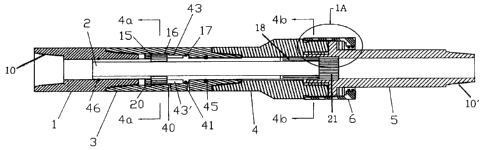
In Fig. 1, the locking swivel apparatus comprises a
retainer sub 1 which is provided with means 10 for making a
threaded connection with standard tubular members, and is
threadably engaged with a lower body 3 to retain a locking
mandrel 2. The locking mandrel 2 is provided with splines
16 and splines 18 to engage splined surfaces 20 and 21
respectively formed both in the swivel mandrel 5 and in the
lower body 3 for locking the swivel to the lower body to
prevent rotation of the drill string (not shown) which
would be connected to threads 10'.
The retainer sub 1, locking mandrel 2, and lower body
3 of the lockable swivel apparatus engage the top sub 4 of
an inline swivel. Brass packing rings 27 and washpipe
packing 26 seal swivel mandrel 5 permitting fluid
communication through the annulus of the inline swivel
apparatus without leakage. Swivel mandrel 5 is secured to
the circumferentially spaced brass wear ring 31, bearing
29, packing 28 and 30 by a bearing retainer nut 6, which is
threadably engaged on the top sub 4 by threads 33 and 33'.
The lower body 3 is threadably engaged into the top sub 4
of the inline swivel. The swivel mandrel 5 of the inline
swivel is provided with inner splines 21 to engage the
CA 02605260 2007-11-01
6
outer splines 18 formed on the lower end of the locking
mandrel 2 which extends through the lower body 3 and top
sub 4.
Hydraulic fitting ports 40 and 41 provided in the
lower body 3 are disposed on either side of a dynamic seal
means 17 in a chamber formed between exterior of the
locking mandrel 2 and the interior wall 43 of the lower
body 3 to move the locking mandrel 2 either up or down and
thereby into or out of engagement with the splines 21 on
the swivel mandrel 5 and the splines 20 in the lower body
3. The locking mandrel 2 moves up or down as provided and
is stopped by shoulder 15 from moving into retainer sub 1.
Washpipe packer or seal means 45 and 46 are provided
to make a hydraulic seal in chamber 43' to enable an
operator on the rig floor to selectively move the locking
mandrel 2 into and out of engagement with the swivel
mandrel and to thereby control undesired rotation of the
drill string by actuating a hydraulic pump.
In the preferred embodiment, standard hydraulic lines
are attached to hydraulic fitting ports 40 and 41 and
connected by hydraulic lines to a pump controlled by the
operator in a manner well known to those in the industry.
The operator switches--the flow of hydraulic fluid to port
40 if locking of the swivel is desired, and to port 41 if
unlocking of the swivel is desired.
Figure 2 of the drawings shows the detail of the
bearing surfaces disposed around the swivel arrangement.
Figures 3a and 3b are cross sectional views of the
CA 02605260 2007-11-01
7 -
cooperating engagement surfaces or splines of the locking
mandrel and the swivel mandrel.
when used in conjunction with wireline services on
directional drilling operations, the magnetic or gyro-type
tools have direct entry into the pipe string through the
top entry sub. Once the tools have been landed in the
down-hole-guide sub, or in the wet-connect sub, the pipe
string can then be oriented using the rotary table, while
maintaining the swivel in the unlocked position. Once the
desired orientation has been attained, the pipe can then be
held in position by locking the swivel and engaging the
back-brake on the top drive unit.
Should minor adjustments in the orientation be
required, this can be easily accomplished since the locking
mechanism in the swivel incorporates a splined shaft which
provides eighty three separate orientations per revolution.
Utilization of this package enables drilling two or three
joint per connection, depending on rig height, and
eliminates holding the back-torque with the rig tongs.
In pipe recovery operations, once the downhole package
has been assembled, the wireline tools always have direct
entry into the pipe string which eliminates having to
separate and re-connect the pipe string each run. Also,
the tools can be fully lubricated which minimizes any
bending, flexing or jarring of sensitive instrumentation.
All explosive devices, such as string shots, cutters,
severing tools and perforating guns are contained within
the lubricator while in close proximity of the rig floor.
This minimizes exposure to potential injury in the event of
CA 02605260 2007-11-01
- 8 -
an inadvertent detonation. The assembly enables operation
under surface pressure, while performing pump-down
operations, and while employing a grease injector system.
Between wireline runs, the operator retains the ability to
continue circulation and reciprocation of the pipe, thus
preventing additional subsidence and sticking. During
actual operations both make-up and reverse torque can be
applied to the pipe and worked-down without utilizing the
rig tongs. Prior to the ability to maintain the torque by
setting the swivel in the locked position, torque was
maintained on the drill string by attaching pipe tongs to
the string and cabling the end of the tong to the drilling
structure while the operator reciprocates and manipulates
the string. The disengagement of the pipe tong cabling
while torque was being applied caused the tongs and cabling
to dangerously rotate rapidly around the rig floor.
During pipe recovery operations, the wireline engineer
must apply right hand, "make-up," torque to the pipe string
and work it down in order to assure that the entire string
is sufficiently tight before applying the left hand, "back
off," torque. With the pipe string setting on the slips in
the rotary, usually at neutral weight, the right hand
torque is applied to the drill string in an amount less
than the full make-up torque of the string and then
releasing or relaxing the brake on the drill string. Non-
absorbed torque will "come back." This process is then
repeated three to four times, with each iteration providing
greater amounts greater amounts of torque, until a pre-
determined amount based upon the recommended maximum torque
CA 02605260 2007-11-01 ~=
9 -
load for the type of pipe and connections has been reached.
The drilling engineer also uses the behavior of the drill
string during this process to determine the amount of
torque the hole is "trapping" or whether the torque is
being distributed evenly through-out the pipe string or
encountering premature build up because of angle changes,
dog legs, etc.
With the right hand torque being held securely with
the rotary back-brake or the rotary lock, the operator
switches the manual control valve on the hydraulic pump
from the open/unlocked position to the closed/locked
position to begin closing the locking mechanism in the
swivel. The operator should count the strokes and to
observe the sudden pressure increase. If the number of
strokes and the pressure change are consistent with the
results experienced in the installation phase, the internal
lock is completely closed. To assure that the swivel
remains in locked position, it is recommended that
approximately 500 pounds of back pressure against the lock
be maintained.
After determining that the back-brake on the top drive
unit is securely locked, the operator commences releasing
the rotary table back-brake and slowly transfers the pipe
torque to the top drive unit. When the torque is being held
with the rotary lock, engage the top drive and slowly
increase the amperage until the torque is transferred and
the rotary lock can be released. Once all the torque has
been transferred to the top drive unit, the wireline access
port will become shifted approximately 10.8 degrees to the
CA 02605260 2007-11-01
- 10 -
left. of true alignment. However, in this procedure the
port will not shift if using a single joint but will shift
10.8 degrees to the right if using a lubricator joint.
This is predicated on having one round per thousand in the
drill pipe and the shifts are directly proportional to the
amount of torque that is being transferred from the drill
pipe into the assembly joint between the top entry adapter
sub and the top drive unit, or the lubricator joint between
the top entry sub and the swivel.
Once satisfied that the pipe string has been
sufficiently tightened to the point of accepting left-hand
torque without breaking pre-maturely, the pipe string can
be placed back on the slips in the rotary table. The back-
brake or the lock on the rotary should then be engaged.
With the weight of the pipe string now resting on the
rotary, the torque being held with the top drive can be
slowly transferred to the rotary.
With the torque transferred and the top drive
disengaged, the operator switches the controls on the
hydraulic pump and opens or "unlocks" the swivel. As
before, the operator should count the strokes and watch the
pressure to assure that the swivel is totally open, or
"unlocked." Again, it is recommended that approximately
500 pounds of back pressure be maintained to assure that
swivel remains in the open or "unlocked" position. The
wireline access sub should then be realigned with the
derrick sheave and the top drive unit relocked. The torque
can then be released with the rotary table. At this point,
the engineer may elect to reciprocate the pipe string in
CA 02605260 2007-11-01
- 11 -
order to work out any remaining trapped torque prior to
running the free point or other services.
The invention also enables rotating, circulating and
reciprocating the pipe while running and pumping-down
various wireline-tools and performing various services,
i.e., end-of-hole gyros, "measure-while-drilling" (M-W-D)
retrieval tools, pipe recovery service tools, gamma ray
logging devices or total "vertical depth" (T.V.D.) devices
and other logging or perforating service tools.
Since the package can be assembled in a variety of
configurations, customer preference, operating conditions
and job requirements, whether involving directional
drilling, pump downs, grease injectors, MWD retrieval, coil
tubing or pipe recovery, will strongly influence which
configuration is most advantageous for the job to be
performed.
Once the chosen packages described above have been
installed and tightened, the hydraulic hoses should be
attached to the locking swivel and the hand pump. The
hoses, the swivel and the hand pump have mated quick-
connects which assures that the labeling on the hand pump,
closed/locked and open/unlocked corresponds correctly with
the direction of movement and position of the internal
locking mechanism within the swivel.
Lock the rotary table, or attach the back-up rig tongs
to the joint of pipe in the rotary, and the assembly can be
tighten to maximum torque allowed using the top drive unit.
Engage the top drive unit and slowly increase the
amperage until the maximum foot pounds of torque allowed
CA 02605260 2007-11-01
- 12 -
for the particular drill pipe being used in the upper
assembly has been reached. Reduce the amperage to zero and
then increase back to maximum allowed amperage at least one
or two more times.
Once the assembly has been properly tightened and the
top drive amperage reduced to zero, unlock the rotary, or
release the back-up tongs, and then open, "unlock", the
swivel.
Use the top drive unit and slowly orient the upper
assembly until the wireline access port in the top entry
sub is in perfect alignment with the wireline sheave in the
derrick. The top drive unit should then be locked in this
alignment and secured so as to prevent inadvertent
unlocking.
Upon making one final check and assuring that the top
drive is locked in the aligned position and the swivel is
in the unlocked position, the assembly will be ready to
begin operations.