Note: Descriptions are shown in the official language in which they were submitted.
CA 02605319 2007-09-28
PRINTING COUPLE OF A PRINTING PRESS
BACKGROUND OF THE tNVENTION
1. Field of the Invention
The present invention generally relates to the field of printing presses and,
more particularly, to a printing couple of a printing press.
2. Description of the Related Art
Printing couples of printing presses have a form cylinder, a transfer
cylinder rolling on the form cylinder, an impression cylinder rolling on the
transfer
cylinder, an inking couple, and possibly a dampening unit. By means of the
inking couple, the printing ink can be applied to the form cylinder, namely,
to at
least one printing form positioned on the form cylinder. The form cylinder is
also
referred to as a plate cylinder. The transfer cylinder, which carries at least
one
blanket or rubber sleeve positioned on it, transfers the printing ink to the
substrate, where the substrate can be moved through a printing gap formed
between the transfer cylinder and the impression cylinder. The transfer
cylinder
is also called the blanket cylinder. In the case of rotary printing presses,
several
printing couples are usually combined into a printing unit; in this case, the
impression cylinder of a printing couple of a printing unit either rolls as a
so-called
"satellite" cylinder on several transfer cylinders of different printing
couples of the
printing unit or is configured as a transfer cylinder of a different printing
couple of
the printing unit.
CA 02605319 2007-09-28
To ensure the proper transfer of ink in the printing couple, a defined
pressure is required between the form cylinder and the transfer cylinder and
also
between the transfer cylinder and the impression cylinder.
As a result of deflections of the cylinders during the operation of the
printing couple, the pressure between the cylinders can vary in the axial
direction,
so that the ink is not transferred uniformly along the width or axial
dimension of
the cylinders. As a result, print quality is negatively affected. In
particular, this
type of non-uniform ink transfer caused by deflections of the cylinders as
they roll
over each other is evident when the cylinders are relatively slender, i.e.,
cylinders
which are relatively long in the axial direction and have a relatively small
diameter.
It is therefore apparent there is need to create a printing couple of a
printing press that solves the foregoing problems.
SUMMARY OF THE INVENTION
This and other objects and advantages are achieved in the present
invention by providing a spindle drive that can be rotatably driven by two or
more
series-connected electric motors. In accordance with the invention, the
diameter
of at least one cylinder, i.e., at least one of the form cylinder, the
transfer cylinder
and the impression cylinder, is graduated in the axial direction.
The foregoing and other problems are solved by a printing couple of a
printing press that comprises a form cylinder, a transfer cylinder rolling on
the
form cylinder, an impression cylinder rolling on the transfer cylinder, and an
inking couple operable to transfer printing ink to the form cylinder. The
transfer
cylinder carries at least one blanket or rubber sleeve positioned on the
transfer
2
CA 02605319 2007-09-28
cylinder, transfers the printing ink to a substrate, where the ink is
transported
through a printing gap formed between the transfer cylinder and the impression
cylinder, and the diameter of at least one of the form cylinder, the transfer
cylinder and the impression cylinder is graduated in the axial direction
In accordance with the invention, deflections of the cylinders of a printing
couple are compensated for by graduating the diameter of at least one cylinder
in
the axial direction, i.e., across its width. As a result, especially in the
case of
slender cylinders, it becomes particularly possible to counteract the non-
uniform
transfer of ink caused by the deflection of such slender cylinders. Print
quality
can thus be improved.
Generally, the at least one of form cylinder, the transfer cylinder and the
impression cylinder can have a diameter that is graduated in the axial
direction.
However, it is preferable for only the impression cylinder to be provided with
a
diameter which is graduated in the axial direction.
Other objects and features of the present invention will become apparent
from the following detailed description considered in conjunction with the
accompanying drawings. It is to be understood, however, that the drawings are
designed solely for purposes of illustration and not as a definition of the
limits of
the invention, for which reference should be made to the appended claims. It
should be further understood that the drawings are not necessarily drawn to
scale
and that, unless otherwise indicated, they are merely intended to conceptually
illustrate the structures and procedures described herein.
3
CA 02605319 2007-09-28
BRIEF DESCRIPTION OF THE DRAWINGS
The various features, functions and advantages characterizing the
invention will be better understood by reference to the detailed description
which
follows, taken in conjunction with the accompanying drawing. It should be
understood that the drawing is not necessarity drawn to scale and that, unless
otherwise indicated, it is merely intended to conceptually illustrate the
structures
and procedures described herein.
Figure 1 shows a schematic diagram of a transfer cylinder of a printing
couple in accordance with an exemplary embodiment of the invention;
Figure 2 shows a schematic diagram of a transfer cylinder of a printing
couple in accordance with another exemplary embodiment of the invention;
Figure 3 shows a schematic diagram of an impression cylinder of a
printing couple in accordance with a further exemplary embodiment of the
invention;
Figure 4 shows an arrangement of the form cylinder, a transfer cylinder, an
impression cylinder in accordance with the exemplary embodiments of the
invention; and
. Figure 5 shows a schematic diagram of an intermediate element arranged
in accordance with an embodiment of the invention.
DETAILED DESCRIPTION OF THE PRESENTLY PREFERRED EMBODIMENTS
The present invention relates to a printing couple of a printing press, such
as a rotary printing press, where the printing couple has a form cylinder 8, a
transfer cylinder 10, 18, an impression cylinder 28, an inking couple, and
preferably a dampening unit (see Fig. 4). The inking couple is used to apply
4
CA 02605319 2007-09-28
printing ink to the form cylinder 8 or plate cylinder, i.e., to the printing
forms which
are positioned on the form cylinder.
The blanket or rubber sleeve, at least one of which is present on the
transfer cylinder or blanket cylinder, transfers the ink to the substrate to
be
printed, which is transported through a gap formed between the transfer
cylinder
or blanket cylinder and the impression cylinder.
In contemplated embodiments, several printing couples are combined into
a printing unit. Here, the impression cylinder of the printing couple of a
printing
unit is either a satellite cylinder rolling on several transfer cylinders of
different
printing couples or a transfer cylinder of a different printing couple of the
printing
unit.
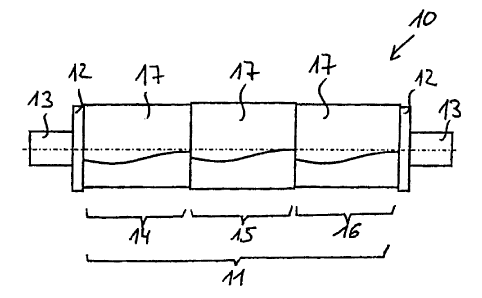
Figure 1 shows a schematic illustration of a transfer cylinder or blanket
cylinder 10 of a printing couple of a printing press in accordance with an
exemplary embodiment of the invention. The transfer cylinder 10 includes a
cylinder base body 11 with a bearer ring 12 and a shaft joumal 13 at each end.
The bearer rings 12 are used to adjust the nominal size of the transfer
cylinder
10, and the shaft journals 13 are used to support the cylinder rotatably in a
machine stand.
In the exemplary embodiment shown in Figure 1, the diameter of the
cylinder base body 11 is graduated in the axial direction. In the exemplary
embodiment shown in Figure 1, the cylinder base body 11 is divided in the
axial
direction into three segments 14, 15, 16 such that the middle segment 15 has a
larger diameter than the lateral segments 14 and 16.
Blankets 17, each of which have identical thicknesses, are arranged on
the segments 14, 15, and 16 of the cylinder base body 11 of the transfer
cylinder
5
CA 02605319 2007-09-28
10. As deriveable from Figure 1, the outside diameter of the segments 14, 15,
and 16 of the cylinder base body 11 are slightly smaller than the outside
diameter
of the bearer rings 1. However, after positioning the blankets 17 on the
segments
14, 15, 16, the transfer cylinder 10 will have an outside diameter in the area
of
the segments 14, 15, 16 that is slightly larger than that of the bearer rings
12.
In the preferred embodiment, only the transfer cylinder 10 of a printing
couple is configured in the manner shown in Figure 1. Alternatively, however,
it
is also possible, in addition to the transfer cylinder or alternatively to the
transfer
cylinder, to configure at least one of the form cylinder and the impression
cylinder
in the manner shown in Figure 1, so that these cylinders will have several
segments of different diameters adjacent to each other in the axial direction.
Figure 2 shows a transfer cylinder 18 of a printing couple of a printing
press in accordance with another exemplary embodiment of the invention, where
the transfer cylinder 18 of Figure 2, similarly to the transfer cylinder 10 of
the
embodiment shown in Figure 1, has a cylinder base body 19 with a bearer ring
20
and a shaft journal 21 at each end.
With specific reference to Figure 2, the cylinder base body 19 of the
transfer cylinder 18 has a uniform diameter over the entire axial dimension.
In
accordance with the embodiment shown in Figure 2, this diameter is smaller
than
the diameter of the bearer rings 20. Blankets 25, 26, 27, each of which have
different thicknesses, are arranged on the various axial sections 22, 23, 24
of the
cylinder base body 19 having the uniform diameter. In accordance with the
exemplary embodiment shown in Figure 2, for example, the blanket 26 on the
middle axial section 23 has a greater thickness than the blankets 25 and 27 on
the lateral axial sections 22 and 24.
6
CA 02605319 2007-09-28
A feature that is common to both exemplary embodiments, i.e., those
shown in Figures 1 and 2, is that the transfer cylinder 10, 18, i.e., the
circumference of its cylinder base body 11, 19, carries or includes blankets
17,
25, 26, 27 and that the diameter is graduated in the axial direction.
In both of these contemplated embodiments, the diameter of a middle
segment 15 or of a middle axial section 23 is larger than that in the area of
the
lateral segments 14, 16 or of the lateral axial sections 22, 24 to compensate
for
the deflection of the cylinder and to ensure that pressure is exerted
uniformly
along the entire axial dimension of the cylinder and, thus, ensure that the
ink is
transferred uniformly.
In contrast to the exemplary embodiments of Figures 1 and 2, in another
contemplated embodiment, a transfer cylinder with a diameter graduated in the
axial direction is provided by using a cylinder base body having a uniform
diameter in the axial direction and blankets having uniform thicknesses that
are
positioned on the cylinder base body. In addition, an intermediate element is
arranged at least between the middle axial section of the cylinder base body
and
the blanket or each blanket to be positioned on the middle axial section, so
that
the diameter of the transfer cylinder is again larger in the middle axial
section
than in the lateral axial sections. This intermediate element is preferably an
underpacking foil (see Fig. 5), which is bonded either to the cylinder base
body in
the middle axial section or to the blanket in question. Even though the
underpacking is not shown in the drawings, the underpacking being located
underneath the location of the middle axial section should be readily apparent
to
the skilled person.
7
CA 02605319 2007-09-28
It is also possible to combine the above-described measures with each
other; that is, the diameter of the cylinder base body can be graduated in the
axial direction, blankets of different thicknesses can be positioned in the
area of
the individual segments, and it is also possibly to use intermediate elements
between the corresponding segments and the blankets.
The contemplated embodiments described with reference to Figures 1 and
2 are preferred exemplary embodiments of a printing couple, where the transfer
cylinder has a diameter graduated in the axial direction in the manner
previously
specified. Moreover, as previously described, the form cylinder of the
printing
couple can also be configured in the manner described above but with printing
plates, as opposed to blankets, that are positioned on the cylinder base body.
In an alternative embodiment, an impression cylinder is configured in the
same manner as previously described with respect to transfer cylinders. Figure
3
shows an impression cylinder 28 of a printing couple in accordance with the
contemplated embodiment, the diameter of which is graduated in the axial
direction. Jn the exemplary embodiment shown in Figure 3, the impression
cylinder 28 has a cylinder base body 29 that is divided in the axial direction
into
three segments 30, 31, 32 with different diameters such that that the middle
segment 31 has a larger diameter than the two lateral segments 30 and 32. A
bearer ring 33 and a shaft journal 34 are again present at each end of the
cylinder.
It should. be noted that that the differences in the diameters of the
cylinders
are in the range of a few hundredths of a millimeter. However, diameter
differences on this scale are sufficient to compensate for deflections of the
cylinders during their operation.
8
CA 02605319 2007-09-28
Thus, while there have been shown and described and pointed out
fundamental novel features of the invention as applied to a preferred
embodiment
thereof, it will be understood that various omissions and substitutions and
changes in the form and details of the devices illustrated, and in their
operation,
may be made by those skilled in the art without departing from the spirit of
the
invention. Moreover, it should be recognized that structures shown and/or
described in connection with any disclosed form or embodiment of the invention
may be incorporated in any other disclosed or described or suggested form or
embodiment as a general matter of design choice. It is the intention,
therefore, to
be limited only as indicated by the scope of the claims appended hereto.
9