Note: Descriptions are shown in the official language in which they were submitted.
CA 02605538 2007-10-22
WO 2006/116666 PCT/US2006/016193
SYSTEM AND METHOD FOR BONDING CLOSURE
OF AN INTRA-CARDIAC OPENING USING ENERGY
Technical Field
[0001] The invention generally relates to devices, systems, and related
methods
for closing intracardiac openings. More particularly, the invention features
devices,
systems, and related methods for the percutaneous transluminal closure of
patent
foramen ovale (PFO).
Background
[0002] The human heart is divided into four compartments or chambers. The
left and right atria are located in the upper portion of the heart and the
left and right
ventricles are located in the lower portion of the heart. The left and right
atria are
separated from each other by a muscular wall, the intra-atrial septuin, and
the
ventricles are separated by the interventricular septum.
[0003] Either congenitally or by acquisition, abnormal openings (holes or
shunts) can occur between the chainbers of the heart or between the great
vessels,
causing inappropriate blood flow. Such deformities are usually congenital and
originate during fetal life when the heart forms from a folded tube into a
four
chambered, two-unit, i.e., atrial and ventricular, system. The septal
deformities
result from the incomplete formation of the septum, or muscular wall, between
the
left and right chambers of the heart and can cause significant problems.
[0004] One such septal deformity or defect, a patent foramen ovale, is a
persistent, usually flap-like opening in the wall between the right atrium and
the left
atrium of the heart. Since left atrial pressure is normally higlier than right
atrial
pressure, the flap typically stays closed. Under certain conditions, however,
right
atrial pressure exceeds left atrial pressure, creating the possibility for
abnormal right
CA 02605538 2007-10-22
WO 2006/116666 PCT/US2006/016193
to left shunting of venous blood that can allow blood clots and other toxins
to enter
the systemic circulation. This is particularly problematic for patients who
are prone
to forming venous thrombus, such as those with deep vein thrombosis or
clotting
abnormalities.
[0005] Nonsurgical (i.e., percutaneous) closure of a patent foramen ovale and
similar cardiac openings, such as an atrial septal defect or a ventricular
septal defect,
can be achieved using a variety of mechanical closure devices. These closure
devices typically have a metallic structural framework with a scaffold
material
attached thereto. Many currently available closure devices, however, are often
complex to manufacture, are inconsistent in performance, require a technically
complex implantation procedure, lack anatomic conformability, and lead to
complications (e.g., thrombus formation, chronic inflammation, residual leaks,
perforations, fractures, and conduction system disturbances).
[0006] Improved devices, systems, and related methods for closing cardiac
openings, such as, for example, a patent foramen ovale, are, therefore,
needed.
Summary of the Invention
[0007] The present invention provides a closure system and related method for
the percutaneous transluminal closure of an intracardiac opening. In one
aspect, a
system of the invention may include, for example, a catheter including a lumen
axially disposed between a proximal end and a distal end and containing an
elongated member slideably disposed in the lumen of the catheter. The
elongated
member has a length between a proximal end and a distal end. In one
embodiment,
the elongated member has a plurality of spokes at the distal end. An energy
activatable bonding material is positioned on the outer surface of each of the
plurality of spokes. An energy source, such as a radio frequency energy,
electrical
resistance, ultrasound energy, laser energy, chemical energy, microwave
energy,
sonic energy, or a therinal resistance heating energy source, is operatively
connected
to the proximal end of the elongated member. The bonding material is activated
by
transferring energy from the energy source to the bonding material. In one
2
CA 02605538 2007-10-22
WO 2006/116666 PCT/US2006/016193
embodiment, the elongated member transfers energy from the energy source to
the
energy activatable bonding material.
[0008] Various embodiments of this aspect of the invention include the
following features. The closure system may include bonding material in the
form of
a sleeve having a lumen. The sleeve is slideably disposed on the distal end of
an
elongated member. The bonding material may include a coating releaseably
adhered
to the elongated member wlzich is releasable on application of energy. The
bonding
material may include bioabsorbable material. Bioabsorbable materials include
bioresorbable materials such as poly-L-lactic acid, polylactic acid, or
polyglycolic
acid, or copolymers or combinations thereof; a biological material, such as
collagen,
cellulose, or animal derived tissues, e.g., the intestinal collagen layer
comprising
tunica submucosa of a porcine small intestine; or a synthetic material such as
an
absorbable or non-absorbable polymer. Absorbable syntlietic material includes
resorbable synthetic material. In one embodiment, the elongated member further
comprises a lumen with a retractable distal stop slideably disposed in the
lumen.
[0009] Moreover, in other embodiments, the system may include an energy riser,
such as a protuberance on the surface of the elongated member, a noninsulated
portion of the elongated member disposed between two insulated portions of the
elongated member, a roughened surface of the elongated member, and a segmental
alteration in the elongated member's material properties, such as by a
secondary or
tertiary process involving coating the material, or placing alternate
materials within
a segment of the elongated member to sharply change the material properties in
the
segment relative to the rest of the elongated member.
[0010] According to another embodiment, the energy riser may be located on the
bonding material, such as a protuberance on the surface of the bonding
material, a
roughened surface of the bonding material, a segmental alteration in the
bonding
material's material properties, such as by a secondary or tertiary process
involving
coating the material, or placing alternate materials within a segment of the
bonding
material to sharply change the material properties in the segment relative to
the rest
of the bonding material.
3
CA 02605538 2007-10-22
WO 2006/116666 PCT/US2006/016193
[0011] In various embodiments of this aspect of the invention, the elongated
member includes a noninsulated portion. The cross section of the elongated
member
may be noncircular.
[0012] According to additional embodiments, the invention includes a first
locator distal to the energy source for positioning the elongated member in
the
cardiac opening. In another embodiment, the invention includes a second
locator
proximal to the energy source for positioning the elongated member in the
cardiac
opening. In another embodiment, the invention includes a first distal locator
and a
second proximal locator. In various embodiments of this aspect of the
invention, the
locator may be a balloon or a hook, and may be insulated or non-insulated.
[0013] In another aspect, the invention relates to a method for percutaneous
transluminal closure of an intracardiac opening via a transvascular route,
e.g., via the
femoral vein, including the steps of inserting a catheter comprising an
elongated
member having a plurality of spokes, and a locator into a patient; locating
the patent
foramen ovale in the patient's heart with the locator; positioning the
elongated
member comprising one or more sleeves of bonding material; applying energy to
the
elongated member; adhering the bonding material to the intracardiac opening;
and
,removing the elongated member and locator; removing the catheter, elongated
member and locator from the patient.
[0014] The foregoing and other aspects, features, and advantages of the
invention will become more apparent from the following description taken,in
conjunction with the accompanying drawings.
Brief Description of the Drawings
[0015] In the drawings, like reference characters generally refer to the same
parts throughout the different views. Also, the drawings are not necessarily
to scale,
emphasis instead generally being placed upon illustrating the principles of
the
invention.
[0016] FIG. 1 is a cutaway view of a heart illustrating a patent foramen
ovale.
4
CA 02605538 2007-10-22
WO 2006/116666 PCT/US2006/016193
[0017] FIG. 2A is a schematic perspective view of the distal portion of a
closure
device, including a delivery catheter and an elongated member, including a
plurality
of distal spokes, for the percutaneous transluminal closure of an intracardiac
opening
according to another illustrative embodiment of the invention.
[0018] FIG. 2B is a schematic perspective view of a closure device, including
a
delivery catheter, an elongated member including a plurality of distal spokes,
and an
energy source, for the percutaneous transluminal closure of an intracardiac
opening
according to an illustrative embodiment of the invention.
[0019] FIG. 3A is a schematic perspective view of a portion of a closure
device
according to another illustrative embodiment of the invention.
[0020] FIG. 3B is a schematic perspective view of a portion of another closure
device according to another illustrative embodiment of the invention.
[0021] FIG. 4 is a schematic perspective view of a portion of a closure device
having energy risers according to another illustrative embodiment of the
invention.
[0022] FIG. 5 is a schematic perspective view of a portion of a closure device
having energy risers according to another illustrative embodiment of the
invention.
[0023] FIGS. 6A and 6B illustrate a series of steps for implanting the closure
device from a top perspective schematic view according to an illustrative
embodiment of the invention.
[0024] FIG. 7A is a side schematic view of a portion of a closure device
including a locator positioned in a patent forainen ovale according to an
illustrative
embodiment of the invention.
[0025] FIG. 7B is a top schematic perspective view of a portion of the locator
of
FIG. 7A according to an illustrative embodiment of the invention.
[0026] FIG. 8 is a side schematic view of a portion of a balloon locator
positioned in a patent foramen ovale according to another illustrative
embodiment of
the invention.
5
CA 02605538 2007-10-22
WO 2006/116666 PCT/US2006/016193
[0027] FIG. 9 is a schematic side view of a portion of a closure device
including
exemplary flexible members for positioning the closure device in an
intracardiac
defect, according to an illustrative embodiment of the invention.
[0028] FIG. 10A is a schematic side view of a portion of a closure device
including a set of flexible members for positioning the closure device in an
intracardiac defect, wherein the flexible members are partially extended from
a
catheter according to an illustrative embodiment of the invention.
[0029] FIG. l OB is a schematic side view of the flexible members of FIG. 10A
fully extended from the opening in the catheter, according to an illustrative
embodiment of the invention.
[0030] FIG. 11 is a schematic side view of a portion of a closure device
including a set of flexible members for positioning the closure device in an
intracardiac defect, according to an illustrative embodiment of the invention.
[0031] FIG. 12A is a schematic side view of a portion of a closure device
including a flexible member for positioning the closure device in an
intracardiac
defect, according to an illustrative embodiment of the invention.
[0032] FIG. 12B is a schematic end-on view of the portion of a closure device
including a flexible member of FIG. 12A, according to an illustrative
embodiment of
the invention.
[0033] FIG. 13A is a schematic side view of a portion of a closure device
including spiral shaped flexible member according to an illustrative
embodiment of
the invention.
[0034] FIG. 13B is a schematic end-on view of the portion of a closure device
including the flexible member of FIG. 13A, according to an illustrative
embodiment
of the invention.
[0035] FIG. 14A is a schematic side view of a portion of a closure device
including flexible members collapsed within a catheter, according to an
illustrative
embodiment of the invention.
6
CA 02605538 2007-10-22
WO 2006/116666 PCT/US2006/016193
[0036] FIG. 14B is an illustration of the set of flexible members of FIG. 14A,
in
an extended configuration beyond the distal end of the catheter, according to
an
illustrative embodiment of the invention.
Detailed Description of the Invention
[0037] The present invention features systems and related methods for closing
cardiac openings, such as, for example, the patent foramen ovale described
below.
'[0038] FIG. 1 depicts a cutaway view of a heart 20. The heart 20 includes a
septuin 24 that divides a right atrium 26 from a left atrium 32. The septum 24
includes a septuni secundum 36 and a septum primum 40. An exemplary cardiac
opening, a patent forainen ovale 44, that is to be corrected by the system and
related
method of the present invention is located between the septum secundum 36 and
the
septum primum 40. The patent foramen ovale 44 provides an undesirable fluid
communication between the right atrium 26 and the left atrium 32 and, under
certain
conditions, allows for the abnormal shunting of blood and other toxins between
the
right atrium 26 and the left atrium 32. If the patent foramen ovale 44 is not
closed or
obstructed in some manner, a patient is placed at higher risk for an embolic
stroke in
addition to other circulatory abnormalities.
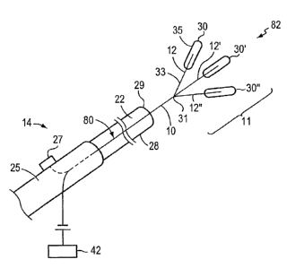
[0039] FIGS. 2A and 2B are schematic perspective views of a portion of a
closure device 14, including a delivery catheter 28, an elongated member 10,
and an
energy source 42, for the percutaneous transluminal closure of an intracardiac
opening according to an illustrative embodiment of the invention. The closure
device 14, in the illustrative embodiment, for example, includes a handle 25
including an actuator 27, and a delivery catheter 28 including a lumen 22 in
which
the elongated member 10 is slideably disposed. The proximal end 80 of the
elongated member 10 is disposed within the lumen 22 of the delivery catheter
28.
[0040] Referring to FIGS. 2A and 2B, according to one illustrative embodiment
of the invention, the elongated member 10 is slideable from a first position
to a
second position by operator directed axial motion of the actuator 27. The
actuator
7
CA 02605538 2007-10-22
WO 2006/116666 PCT/US2006/016193
27 is operatively joined to the proximal end 80 of the elongated member 10.
While
the delivery catheter 28 is stationary, the elongated member 10 slides from a
first
position, for example, as illustrated in FIG. 2A, wherein the distal end 82 of
the
elongated member 10 is enclosed and collapsed within the lumen 22 of the
delivery
catheter 28, to a second position, for example, as illustrated in FIG. 2B,
wherein the
distal end 82 of the elongated member 10 is in an expanded configuration
beyond
the outside of the lumen 22 of the delivery catheter 28. According to this
illustrative
embodiment, the delivery catheter 28 is stationary during the sliding movement
of
the elongated member 10.
[0041] Referring to FIGS. 2A and 2B, according to another illustrative
embodiment of the invention, the delivery catheter 28 is slideable from a
first
position to a second position by operator directed axial motion of the
actuator 27
while the elongated member 10 is stationary. The actuator 27 is operatively
joined
to the delivery catheter 28. The delivery catheter 28 slides from a first
position, for
example, as illustrated in FIG. 2A, wherein the distal end 82 of the elongated
member 10 is enclosed by and collapsed within the lumen 22 of the delivery
catheter 28, to a second position, for example, wlierein the distal end 82 of
the
elongated member 10 is in an expanded configuration outside of the lumen 22 of
the
delivery catheter 28, as shown, for example, in FIG. 2B. According to this
illustrative embodiment, the elongated member 10 is stationary during sliding
movement of the delivery catheter 28.
[0042] The distal end 82 of the elongated member 10, for the purpose of
illustrating exemplary embodiments of slideable movement illustrated in FIGS.
2A
and 2B, may include, for example, a distal portion 11 of the elongated member
10
having one or more spokes 12. Each spoke 12 has a fixed end 33 and a free end
35,
with the fixed end 33 being connected to the main body of the elongated member
10.
In a further embodiment, bonding materia130 is attached to the elongated
member
10. For example, in one embodiment, bonding material 30 is attached to one
location on the elongated member 10, while in another embodiment, bonding
materia130 is attached to two or more locations on the elongated member 10. In
another embodiment, bonding material 30 is attached to one or more spokes 12.
For
8
CA 02605538 2007-10-22
WO 2006/116666 PCT/US2006/016193
example, bonding material 30 is attached to one location on one or more spokes
12
at the distal end 82 of the elongated member 10 in one embodiment, while in
another
embodiment, bonding material 30 is attached to two or more locations on one or
more spokes 12. In one embodiment, the bonding material 30 is releaseably
coupled
to the elongated member 10 or spoke 12. The slideable movement of the
elongated
member 10 and/or the delivery catheter 28 may be directed, for example, by an
actuator 27 located, for example, on the handle 25 of the closure device 14.
[0043] With continued reference to FIG. 2B, the cross-section of the elongated
member 10 may include a variety of geometric configurations including round,
oval,
square, rectangular and flat (not shown). The distal end 82 of the elongated
member
10, for example, may also include one spoke 12 or a plurality of spokes 12,
12',
12". The shape of the spoke 12 may include a variety of geometric
configurations
including straight, bent, spiral and S-shaped (not shown). Although the
illustrative
embodiment includes three spokes 12, 12', 12", it is contemplated that there
may be
more than tliree spokes, and as many as 16 spokes. Each of the illustrative
spokes
12, 12', 12" may be arranged in the same plane. According to another
embodiment,
the spokes 12, 12', 12" may be arranged in an arc, with each spoke 12
separated
from an adjacent spoke 12', 12" by an angle of separation of between 5 degrees
and
180 degrees. Each spoke 12, 12', 12" includes a portion of bonding material
30,
30', 30", respectively, in the form of a releaseably coupled coating or a
slideably
disposed sleeve, described in greater detail below.
[0044] With continued reference to FIG. 2B, in one embodiment one or more of
spokes 12, 12', 12", (generally 12), is flexibly biased relative to the other
spokes 12,
12', 12"at the distal end 82 of the elongated member 10. Upon deployment of
the
elongated member 10 from the distal end 29 of the catheter 28, the spokes 12,
12',
12" are biased to automatically separate from one another at a pivot point 31
due to
the tension forces between the spokes 12, 12', 12". Alternatively, in another
embodiment, one or more of spokes 12, 12', 12" is pivotally joined to the main
body of the elongated member 10, for example, by a pin or hinge (not shown).
Upon deployment of the elongated member 10 from the distal end 29 of the
catheter
28, the hinge or pin (not shown) is activated via the actuator 27 to cause the
one or
9
CA 02605538 2007-10-22
WO 2006/116666 PCT/US2006/016193
more spokes 12, 12', 12" to pivot relative to the other spokes 12, 12', 12" at
a pivot
point 31.
[0045] With continued reference to FIG. 2B, in one embodiment, a plurality of
wires (not shown) form the elongated member 10. The wires are axially aligned
with one another along the proximal portion of the elongated member 10, e.g.,
collected together in a tube or welded together along the long axis of the
wires (not
shown). At the pivot point 31, the wires are separated in order to form spokes
12.
According to the invention, in one embodiment the number of spokes 12
corresponds to the number of wires that form the elongated member 10. For
example, if three spokes 12 are desired, the elongated member 10 will be made
of
three wires.
[0046] Referring to FIG. 2B, the proximal end 80 of the elongated member 10,
is in communication witll an energy source 42. The energy source 42, in the
illustrative embodiment, for example, provides energy to the elongated member
10.
The energy delivered to the elongated member 10 may be any form of energy
capable of activating the releaseably coupled bonding material 30, for
example, by
decreasing the viscosity and increasing the flow rate of the bonding material
30 or
by increasing the tackiness of the bonding material 30 disposed on the distal
end 82
of the elongated member 10 or on the spokes 12 of the elongated member 10. For
example, the energy may be radio frequency energy, electrical resistance,
ultrasound
energy, laser energy, chemical energy, microwave energy, sonic energy, or
thermal
resistance heating energy.
[0047] FIG. 3A is a schematic perspective view of a portion of a closure
device
14 according to another illustrative embodiment of the invention. According to
this
illustrative embodiment of the invention, the distal end 82 of the spoke 12 of
the
elongated member 10 of the closure device 14 includes a releaseably coupled
bonding material 30. The bonding material 30 may be in the form, for example,
of a
sheet that is wrapped around the elongated member 10 or a spoke 12, a tubular
sleeve that slides over the elongated member 10 or over a spoke 12, or a
coating on
the surface of the distal end 82 of the elongated member 10 or a spoke 12.
According to this illustrative embodiment, for example, the tubular sleeve of
CA 02605538 2007-10-22
WO 2006/116666 PCT/US2006/016193
bonding material 30 contains a lumen 50 which allows the tubular sleeve to be
slideably disposed over the distal end 82 of the elongated member 10 or spoke
12.
For example, in one embodiment, each spoke 12, 12', 12" has a tubular sleeve
of
bonding material 30 that slides over each spoke 12, 12', 12". In one
embodiment,
none of the tubular sleeves of bonding materia130 is connected to any other
tubular
sleeve of bonding material 30. Alternatively, one or more of the sleeves of
bonding
material 30 is connected to one other sleeve of bonding materia130. In a
preferred
embodiment, the releaseably coupled bonding materia130 is energized and
deposited
in the region of the patent foramen ovale 44 or other cardiac defect 44, more
specifically, within the defect 44. Here, the bonding materia130 acts as a
framework
for endogenous tissue in-growth to encourage permanent closure of the cardiac
defect 44 by the patient's own tissue.
[0048] FIG. 3B is a schematic perspective view of a portion of another closure
device 14 according to another illustrative embodiment of the invention.
According
to this illustrative embodiment of the invention, the distal end 82 of the
elongated
member 10 or each spoke 12, 12', 12" of the elongated member 10 of the closure
device 14 includes a tubular sleeve of releaseably coupled bonding material
30, 30',
30". According to this illustrative embodiment, each tubular sleeve of bonding
material 30, 30', 30" contains a lumen 50, 50', 50", respectively, through the
full
length of the sleeve 30, 30', 30" which allows the sleeve of bonding
materia130,
30', 30" to be slideably disposed over the distal end 82 of the elongated
member 10
or of each spoke 12, 12', 12".
[0049] With continued reference to FIG. 3B, according to this illustrative
embodiment of the invention, the elongated member 10 and each spoke 12, 12',
12
of the elongated member 10 contains a lumen 54, 54', 54", respectively,
through
which a retractable distal stop 48, 48', 48", (collectively 48), is slideably
disposed.
The distal stop 48, 48', 48" may be in the form, for example, of a coil,
helix, or
other configuration. The distal stop 48 holds the sleeve of bonding material
30, 30',
30" in place and prevents the bonding material 30 from moving distally along
the
elongated member 10. Once the bonding material 30 is appropriately placed in
the
patent foramen ovale 44, the distal stop 48, 48', 48" is slideably retracted
or
11
CA 02605538 2007-10-22
WO 2006/116666 PCT/US2006/016193
mechanically actuated through the lumen 54, 54', 54" of the elongated member
10
or of each spoke 12, 12', 12" of the elongated member 10. Additionally,
according
to this illustrative embodiment, the elongated member 10 and each spoke 12,
12',
12" of the elongated member 10 contains a proximal stop 46, 46', 46",
respectively,
that prevents the sleeve of bonding material 30, 30', 30" from sliding
proximally
along the elongated member 10 or spoke 12 prior to delivery, for example, in
the
patent foramen ovale 44.
[0050] With continued reference to FIG. 3B, in one embodiment, the bonding
material 30, 30', 30" is releaseably adhered to the elongated member 10 or
releaseably adhered to the spokes 12 of the elongated member 10. Upon
application
of energy from the energy source 42, the bonding material 30 releases from the
elongated member 10. Until application of energy, the bonding material 30 is
adhered to the elongated member 10.
[0051] Bonding materials preferably are biocompatible, nontoxic, and degrade
into nontoxic components. The bonding material may be, for example, a
bioabsorbable polymer including a bioresorbable polymer, a biological
material, or a
biological material with a bioresorbable or bioabsorbable polymer coating.
[0052] Representative bioresorbable or bioabsorbable polymers include, but are
not limited to, polylactides, including poly(L-lactides), polycaprolactone,
polyglycolides, blends and copolymers thereof.
[0053] Representative natural polymers of use as a bonding material in the
present invention include, but are not limited to, biological materials, such
as a
biological tissue scaffold fabricated from, for example, a collagen based
material
derived from the intestine, stomach, skin, bladder, or pericardium of a
porcine
animal, a bovine animal, an equine animal and/or a human. Alternatively, the
natural polymer may be a protein, such as casein, gelatin, gluten, or serum
albumin.
[0054] According to a preferred embodiment, the natural polymer is formed of
collagen, derived from the tunica submucosa of a porcine small intestine, and
delaminated from the other layers of the porcine small intestine by any method
12
CA 02605538 2007-10-22
WO 2006/116666 PCT/US2006/016193
known in the art. Alternatively, collagenous tissue from the fascia lata,
pericardium,
or dura mater of porcine animals or other mammalian sources, such as, for
example,
cows or sheep, may form the tissue scaffold.
[0055] Alternatively, the natural polymer may be formed of one or more
polysaccharides, such as cellulose, dextrans, and polyhyaluronic acid, or
other
biological materials, including but not limited to, deoxyribonucleic acid,
ribonucleic
acid, and mammalian cells including stem cells, capable of encouraging tissue
growth may be used as a bonding material or a component of the bonding
material.
Furthermore, the biological material may be coated wit11 any of the
bioresorbable or
bioabsorbable or natural polymers identified above. Moreover, the bonding
material
may be formed from any combination of the aforementioned materials.
[0056] Energy risers, as contemplated by this invention, are portions of the
energy delivery closure device 14 adapted to increase the intensity or
directionality
of the applied energy transmitted by the energy source 42 to the releaseably
coupled
bonding material 30. Applying energy to a specific location or in a specific
intensity
or duration to the target intracardiac site allows greater flexibility in the
design of an
energy delivery closure device 14 or implant. Energy risers allow the operator
of the
energy delivery closure device 14 greater control over delivery of the energy
to the
target. For example, an energy delivery closure device 14 including energy
risers
may allow for greater or smaller quantities of focused energy to be applied,
tailoring
the energy delivery to the clinical indication and improving the patient
outcome.
[0057] For example, FIG. 4 is a schematic perspective view of a portion of a
closure device 14 according to another illustrative embodiment of the
invention in
which the energy risers are positioned on the elongated member 10 or on the
spoke
12 (not shown) in the form of pyramidal extensions 52. The extensions 52, in
the
illustrative embodiment, for example, may be formed of the same material as
the
elongated member 10. The closure device 14 may have one or more energy risers,
for example, two, three, four, or as many as 100 energy risers.
13
CA 02605538 2007-10-22
WO 2006/116666 PCT/US2006/016193
[0058] FIG. 5 is a schematic perspective view of a portion of a closure device
14
according to another illustrative embodiment of the invention in which the
energy
risers are in the form of at least one, for example, two uninsulated portions
58, 58',
disposed between insulated portions 56, 56', 56" of the elongated member 10 or
of
the spoke 12 (not shown). For example, in one embodiment, a first insulated
portion
56 is disposed next to a first uninsulated portion 58. In another embodiment,
a first
insulated portion 56 is disposed between a first uninsulated portion 58 and a
second
uninsulated portion 58'. In another embodiment, a first uninsulated portion 58
is
disposed between a first insulated portion 56 and a second insulated portion
56'. It
is contemplated that the insulating material coating the insulated portions
56, 56',
56" may be composed of any material that changes the conductivity properties
of
the elongated member 10 relative to the energy delivery portions 58, 58'. For
example, in one embodiment, the material that changes the conductivity
properties
of the elongated member 10. In another embodiment, the material is a polymer
coating.
[0059] Additionally, according to another illustrative embodiment, the energy
risers may be in the form of at least one roughed patch (not shown)
distributed on
the exterior surface of the elongated member 10. For example, in one
embodiment,
at least a portion of the surface of the elongated member 10 is abraded to
roughen
the texture of the surface in order to create an energy riser. In a further
embodiment,
a first roughened patch (not shown) is adjacent to a non-roughened surface
(not
sllown). In yet another embodiment, a first roughened patch (not shown) is
disposed
between a first non-roughened surface (not shown) and a second non-roughened
surface (not shown). In a still further embodiment, a first non-roughened
surface
(not shown) is disposed between a first roughened patch (not shown) and a
second
roughened patch (not shown).
[0060] Furthermore, the energy risers may be in the form of at least one
protuberance (not shown) on the surface of the bonding material 30, a
roughening of
the surface (not shown) of the bonding material 30, altering the material
properties
of the bonding material 30, such as a secondary or tertiary process involving
coating
the bonding materia130 (not shown), and placing alternate materials within a
14
CA 02605538 2007-10-22
WO 2006/116666 PCT/US2006/016193
segment of the bonding material 30 (not shown) to sharply change the material
properties in the segment relative to the rest of the bonding material 30. For
example, in one embodiment, the bonding material 30 includes a material that
is
activated by energy at a rate different than another material in the bonding
material
30. This allows for at least one portion of the bonding material 30 to be
activated
before another portion of the bonding material 30. In anotlier embodiment, the
bonding material 30 includes a portion that is more dense than another portion
of the
bonding material 30. This allows for one portion to be activated before
another
portion of the bonding material 30.
[0061] Furthermore, it is contemplated that other methods of targeting energy
delivery through energy risers may be employed. For example, the cross-
sectional
geometry of the elongated member 10 or the bonding material 30 may be
modified,
such as rectangular, square, oval, round, or flat (not shown). Alternatively,
the
elongated member 10 may be spliced into a plurality of thinner elongated
members
(not shown), or the material properties of the elongated member 10 or the
bonding
material 30 may be altered, for example, by performing a secondary or tertiary
process involving coating at least a portion of the elongated member 10 or the
bonding material 30. For example, in one embodiment, at least a portion of the
elongated member 10 is coated with a polymer or a metal. In another
embodiment,
the material properties of the elongated member 10 are segmentally altered,
allowing
one segment of the elongated member 10 to have different conductive properties
from another segment. For exanlple, in one embodiment, the elongated member 10
includes a first portion of a first density and a second portion of a second
density. In
another embodiment, the elongated member 10 includes a first portion having a
first
level of conductivity and a second portion having a second level of
conductivity.
[0062] FIGS. 6A and 6B illustrate a series of exemplary steps for a metllod of
closing an intracardiac defect with the closure device 14, according to an
illustrative
embodiment of the invention. Referring to FIG. 6A, the closure device 14
includes
an elongated member 10 slideably disposed in the lumen 22 of the delivery
catheter
22, that has been percutaneously and transluminally positioned within the
patent
foramen ovale 44. The illustrative elongated member 10, for example, includes
a
CA 02605538 2007-10-22
WO 2006/116666 PCT/US2006/016193
plurality of spokes 12, 12', 12". Each spoke 12, 12', 12" includes a portion
of
releaseably coupled bonding material 30, 30', 30", respectively, in the form
of a
coating or a slideably disposed sleeve.
[0063] With continued reference to FIG. 6A, according to the illustrative
embodiment, the spokes 12, 12', 12" of the elongated member 10 are inserted
past
the septuin secundum 36 and into the cardiac opening, e.g., the patent foramen
ovale
44. The spokes 12, 12', 12" are then positioned between the septum secundum 36
and the septum primum 40. The releaseably coupled bonding material 30, 30',
30",
either coating the spokes 12, 12', 12" or in the form of a sleeve slideably
disposed
over the distal end 82 of the spokes 12, 12', 12", is also positioned between
the
septum secundum 36 and the septum primum 40 of the cardiac opening.
[0064] Still referring to FIG. 6A, wlZen energy transmitted from the energy
source 42 (not shown) is applied to the elongated member 10, the energy is
transferred, at least in part, to the releaseably coupled bonding material 30.
For
example, when the energy is applied, the tackiness of the bonding material 30
increases and/or the flow rate of the energized bonding materia130 increases
and the
viscosity of the bonding material 30 decreases.
[0065] With continued reference to FIG. 6A, according to one illustrative
embodiment of the invention, the energized bonding materia130, for example, is
released from the elongated member 10 and associates with the tissue of the
septum
secundum 36 and the septum primum 40. Following association of the bonding
material 30 to the tissue, the elongated member 10 is retracted from the
intracardiac
opening, leaving the bonding material 30 behind (as depicted in FIG. 6B) in
the
intracardiac defect 44.
[0066] Still referring to FIG. 6A, according to another illustrative
embodiment
of the invention, the proximal end 80 of the elongated member 10 or the spoke
12
contains a proximal stop 46 (not shown) and the distal end 82 of the elongated
member 10 or the spoke 12 contains a retractable distal stop mechanism 48 (not
shown). According to this embodiment, the distal stop mechanism 48 (not shown)
is
reversibly attached to the sleeve of releaseably coupled bonding material 30,
for
16
CA 02605538 2007-10-22
WO 2006/116666 PCT/US2006/016193
example, by a hook and loop, ball and socket, claw, screw, or other reversible
attachment mechanism. Furthermore, the elongated member 10 may be in the form
of a hollow tube (not shown), with the retractable distal stop mechanism
slideably
disposed within the lumen 54 (not shown) of the hollow tube elongated member
10.
[0067] With continued reference to FIG. 6A, according to one exemplary
embodiment of the invention, the elongated member 10 or the spoke 12
containing
the releaseably coupled bonding material 30 is inserted between the septum
secundum 36 and the septum primum 40 of the patent foramen ovale 44, energy is
applied to the elongated member 10, and the energized bonding material 30
associates with the tissue of the septum secundum 36 and the septum primum 40.
Following association of the bonding material 30 to the tissue, the distal
stop
mechanism 48 (not shown), for example, is disengaged from the bonding material
30, retracted into the hollow tube of the exemplary elongated member 10, and
the
elongated member 10 retracted from the intracardiac opening, leaving the
bonding
material 30 behind in the cardiac defect 44 (as depicted in FIG. 6B).
[0068] FIG. 6B illustrates a top schematic perspective view of a portion of a
closure device 14 including a closed intracardiac opening according to an
illustrative
embodiment of the invention. FIG. 6B illustrates the positioning of the
energized
bonding material 30 after it is released from the elongated member 10. The
bonding
material 30, 30', 30" is placed between the septum secundum 36 and the septum
primum 40 to encourage tissue in-growth and closure of the intracardiac
opening.
[0069] Optionally, as illustrated in FIGS. 7A, 7B, and 8, the closure device
14
(not shown) further includes a locator 60, 62 (generally 60). The locator 60
may be
connected to the elongated member 10 or either to or within the delivery
catheter 28
(not shown). In one embodiment, the locator 60 is integral to the elongated
member
10, and is disposed at the distal end 82 of the elongated member 10. In
another
embodiment, the locator 60 is maintained within a collapsed state within the
lumen
54 of the elongated member 10, and is deployed to an open state beyond the
distal
end 82 of the elongated member 10 in order to position the elongated member 10
in
the patent foramen ovale 44. In one embodiment, the physician positions the
locator
60 between the septum secundum 36 and the septum primum 40 of the patient's
17
CA 02605538 2007-10-22
WO 2006/116666 PCT/US2006/016193
heart. The locator 60 is used by the physician, for example, to limit movement
of
the septum secundum 36 and of the septum primum 40 prior to positioning, as
explained above, the elongated member 10 and the bonding materia130 within the
patent foramen ovale 44. The locator 60 also serves to position the distal end
(not
shown) of the delivery catheter 28 (not shown) in the area where the septum
secundum 36 and the septum primum 40 overlap.
[0070] Exemplary locator devices, including flexible members suitable for
stabilizing cardiac tissues in a patient and for placing the elements
described above
in the area where the septum secundum 36 and the septum primum 40 overlap
include those described below and those described in U.S. Patent Application
No.
10/660,444, filed September 11, 2003, and published on May 13, 2004, as U.S.
Patent Application Publication No. 2004-0092973, which is incorporated herein
by
reference in its entirety. For example, the locator 60 may: i) be a flexible
coil
having a spiral shape, ii) include three flexible hexagonal members forming,
generally, a planar array, iii) include two flexible members, each one of
which
includes a leg, such as a wire, that is pre-shaped to articulate one or more
times upon,
exit from a lumen, iv) include two flexible members, each one of which
includes a
loop section, or v) be a single flexible member that forms a closed loop.
[0071] In the illustrative embodiment depicted in FIG. 7A, the locator 60 is
in
the form of a hook. The locator 60 may be inserted into the cardiac defect 44,
for
example, by inserting the locator 60 past the septum secundum 36 and over the
septum primum 40, through the patent foramen ovale 44. As shown in FIG. 7A,
the
hook 60 may be configured such that the distal end 82 of the hook locator 60
temporarily overhangs the septum primum 40 and maintains the closure device 14
in
the correct orientation between the septum secundum 36 and the septum primum
40
during energy delivery and release of the bonding inateria130 (not shown) in
the
patent foramen ovale 44. The locator 60 may be either distal or proximal to
the site
of energy delivery on the elongated member 10.
[0072] FIG. 7B is a top schematic perspective view of a portion of the locator
60
of FIG. 7A according to anotlZer illustrative embodiment of the invention. In
the
illustrative embodiment, the elongated member 10 includes a locator 60 with
two
18
CA 02605538 2007-10-22
WO 2006/116666 PCT/US2006/016193
hooks 61, 61'. In a further embodiment, the elongated member 10 includes a
locator
60 with only one hook 61. In yet another embodiment, there may be a plurality
of
hooks 61, such as three, four, five or more hooks 61. In one embodiment, the
locator 60 includes a bonding material 30, while in another embodiment, the
locator
does not include a bonding material 30. In one embodiment, the locator 60
conducts
and delivers energy to the tissue contacted by the locator. In another
embodiment,
the locator 60 or portions of the locator 60 are insulated such that energy is
not
transmitted to the contacted tissue through the insulated portions of the
locator 60.
(0073] FIG. 8 is a side schematic view of a portion of the closure device 14
including a balloon locator 62 positioned in a patent foramen ovale 44
according to
another illustrative embodiment of the invention. According to this
illustrative
embodiment, the elongated inember 10 includes, for example, an inflatable
balloon
62 portion near or substantially positioned at the distal end 82 of the
elongated
member. For example, in one embodiment, the balloon 62 is positioned on the
surface at the distal end 82 of the elongated member 10. In another
embodiment, the
balloon locator 62 is maintained within the lumen 54 of the elongated member
10
until it is deployed to locate the patent foramen ovale 44.
[0074] The balloon locator 62 may be inserted into the cardiac opening such
that
the distal end 82 of the elongated member 10 and the balloon locator 62
portion of
the elongated member 10 pass over the septum secundum 36 and then the septum
priinum 40. Following insertion past the septum primum 40, the balloon locator
62
may be inflated using, for example, saline. The elongated member 10 may then
be
retracted until the balloon locator 62 is located at the distal surface of the
septum
primum 40. In this configuration, the balloon locator 62 maintains the closure
device 14 in the correct orientation between the septum secundum 36 and the
septum
primum 40 during energy delivery and release of the bonding materia130 (not
shown) in the patent foramen ovale 44. In one embodiment of the invention, the
balloon locator 62 may or may not include bonding material 30 (not shown). In
another embodiment, the balloon locator 62 is located proximal to the bonding
materia130. Furthermore, in another embodiment the elongated member 10
containing the balloon locator 62 conducts and delivers energy to the tissue
which it
contacts, while in another embodiment, the balloon locator 62 or a portion or
19
CA 02605538 2007-10-22
WO 2006/116666 PCT/US2006/016193
portions of the balloon locator 62 are insulated to inhibit energy delivery by
the
balloon locator 62. In all embodiments, it is contemplated that the locator
60, 62 is
removed after delivery of energy to the target site.
[0075] FIG. 9 illustrates a portion of a closure device 14 according to an
illustrative embodiment of the invention including exemplary flexible members
1142'a and 11 42'b for positioning the closure device 14 in an intracardiac
defect 44.
In one embodiment, the flexible members 1142a and 1142b are disposed at the
distal end 82 of the elongated member 10, distal to the bonding material 30
(not
shown). In anotlier embodiment, the flexible members 1142a and 1142'b are
disposed at the distal end 82 of the elongated member 10, for example, at the
distal
end of a spoke 12. Each of the flexible members 1 142'a and 1142b include a
leg
such as a wire having a first end 1204'a and 1204'b, respectively, joined to
the distal
end 82 of the elongated member 10. Each of the flexible members 1142'a and
1142'b also have a second distal end 1202'a and 1202'b, respectively, that is
free,
i.e., not joined to any other structure of the closure device 14. The
longitudinal axis
of the flexible members 1142'a and 1142'b are oriented substantially parallel
to the
delivery catheter 28 when the flexible members 1142'a and 1142'b are located
within the lumen 22 of the delivery catheter 28. The flexible members 1142a
and
1142'b have a first portion 1272a and 1272b, respectively and a second portion
1270a and 1270b, respectively. The flexible members 1142'a and 1142'b are
disposed witllin the lumen 22 in this contracted position such that the second
ends
1202'a and 1202'b are directed distally 82 towards the opening 1112 in the
distal end
29 of the delivery catheter 28.
[0076] Prior to insertion into the lumen 22, the flexible members 1142'a and
1142'b are preshaped such that the flexible members 1142'a and 1142'b will
assume
a predetermined extended configuration when the flexible members 1142'a and
1142'b are fiee from the confines of the luinen 22. The flexible members
1142'a and
1142'b are freed from the confines of the lumen 22 by moving the flexible
members
1142'a and 1142'b between the contracted position illustrated, for example, in
FIG. 9
.30 and an extended position, such as the extended position depicted in FIG. l
OB.
While in the lumen 22 of the delivery catheter 28, the flexible members 1142'a
and
1142'b apply a force to an inner surface 1210 of the delivery catheter 28 in a
first
CA 02605538 2007-10-22
WO 2006/116666 PCT/US2006/016193
location 1230a and 1230b, respectively, on the inner surface 1210 of the lumen
22
that the flexible members 1142'a and 1142b contact. The force applied by the
preshaped flexible members 1 142'a and 1 142'b to the inner surface 1210 is
the
resultant force associated with the inner surface 1210 constraining the shape
of the
flexible members 1142a and 1142'b so they may fit within the lunlen 22 of the
delivery catheter 28.
[0077] In an embodiment of a closure device referring now to FIG. 10A, the
flexible members 1142'a and 1142b are shown partially extended (in comparison
with the flexible members 1142'a and 1142'b in FIG. 9) so the flexible members
1142'a and 1142b are still substantially parallel to the longitudinal axis of
the
delivery catheter 28. As the elongated member 10 is extended out of the
opening
1112 of the delivery catheter 28, the second ends 1202'a and 1202'b of the
flexible
members 1142'a and 1142b, respectively, undergo an articulation and point,
generally, in a proximal direction toward the handle (not shown). In this
orientation,
the preshaped flexible members 1142'a and 1142'b apply a force to the rim 1156
of
the opening 1112 in the delivery catheter 28 because the rim 1156 of the
opening
1112 constrains the shape of the flexible members 1142a and 1142'b.
[0078] The elongated member 10 is further extended distally, referring now to
FIG. l OB, along the lengthwise dimension (in the positive direction along the
X-
axis) of the lumen 22 until the distal end 82 of the elongated member 10
emerges
from the opening 1112 of the delivery catheter 28. The second ends 1202'a and
1202'b of the exemplary preshaped flexible members 1142a and 1142b,
respectively, undergo an additional articulation and as a result point,
generally,
towards one another. In this extended position, the preshaped flexible members
1142'a and 1142'b no longer apply a force to the delivery catheter 28 because
the
delivery catheter 28 does not constrain the shape of the flexible members
1142'a and
1142'b. In this extended position, each of the flexible members 1 142'a and
1142b is
substantially planar in shape. The plane of each of the flexible members 11
42'a and
1142'b define a plurality of axes that lie in the plane. The plurality of axes
are non-
parallel to (i.e., biased relative to) the longitudinal axis of the delivery
catheter 28.
For example, the plurality of axes defined by the planes of the flexible
members
1142'a and 1142'b are positioned at an angle in the range of about 0 degrees
to about
21
CA 02605538 2007-10-22
WO 2006/116666 PCT/US2006/016193
180 degrees, preferably, about 90 degrees, relative to the longitudinal axis
of the
elongate member 10.
[0079] In alternative embodiments of the invention, the second ends, for
example, the second ends 1202'a and 1202'b, may have a different diameter than
other locations along the length of the flexible elastic members 1142a and
1142'b.
By way of example, an operator may select an apparatus having flexible members
that have second ends 1202'a and 1202'b having a larger diameter to, for
example,
reduce trauma to tissue the second ends 1202'a and 1202'b contact during use.
Alternatively, the second ends 1202'a and 1202'b may have a ball shaped tip.
[0080] FIG. 11 depicts a portion of a closure device 14 including flexible
members for positioning the closure device at an intracardiac defect according
to an
alternative illustrative embodiment of the invention. The exemplary flexible
members 1142"a and 1142"b include a first wire loop section 1220a and a second
loop section 1220b, respectively, as illustrated in FIG. 11. The tip 1406a and
1406b
of the loop sections 1220a and 1220b, respectively, point, generally, towards
one
another and towards the elongated member 10. Loop sections 1220a and 1220b
may, alternatively, be oriented in a variety of directions (e.g., away from
the
elongated member 10 or at a 45 degree angle away from the elongated member
10).
However, the loops 1220a and 1220b of the flexible members 1142"a and 1142"b
will, typically, be oriented such that the flexible members 11 42"a and 11
42"b
including the loop sections 1220a and 1220b are substantially planar, where
the
plane defines a plurality of axes lying in the plane. The plurality of axes
are non-
parallel to (i.e., biased relative to) the longitudinal axis of the delivery
catheter 28
when the flexible members 1142"a and 1142"b are extended distally from the
opening 1112 of the delivery catheter 28. Other embodiments of the flexible
member 1142"a and 1142"b are also contemplated by the invention and are not
limited to those illustrated.
[0081] In an alternative embodiment, referring now to FIGS. 12A and 12B, the
closure device 14 includes a single flexible member 1142"' for positioning the
closure device in an intracardiac defect 44, such as a patent foramen ovale.
The
flexible member 1142"' is disposed at the distal end 82 of the elongated
member 10,
distal to the bonding materia130 according to one embodiment of the invention.
The
22
CA 02605538 2007-10-22
WO 2006/116666 PCT/US2006/016193
flexible member 1142"' has a first end 1206 and a second end 1208; both the
first
end 1206 and the second end 1208 are connected to the distal end 82 of the
elongated member 10. The flexible member 1142"' also has a middle section 1540
located, generally, intermediate the first end 1206 and the second end 1208 of
the
flexible member 1142"'. The flexible member 1142"' thereby forms a closed
loop.
In this embodiment, the flexible member 1142"' is configured so the middle
section
1540 is located, generally in the center of a plane defined by the flexible
member
1142"' as illustrated by the end-on view of FIG. 12B. In this configuration,
the
middle section 1540 of the flexible member 1142"' aids with stiffening the
flexible
member 1142"' as compared with the embodiment of the invention illustrated in
FIGS. l0A and lOB where the flexible members 1142'a and 1142'b have free ends
1202'a and 1202'b, respectively. The stiffening minimizes bending when, for
exainple, the flexible member 1142"' is used by an operator to apply forces to
a
tissue, e.g., the atrial septum. In this configuration, the flexible member
1142 forms
a closed loop that is sized and shaped, for example, to contact a first and
second side
of a tissue, similarly, as described herein.
[0082] In another embodiment of the invention, referring now to FIGS. 13A and
13B, the flexible elastic member 1142"" is a coil (coil-like member) and has a
spiral
shape extending from a narrow first end 1204"" to a broad second end 1202"".
The
flexible elastic member 1142"" assists in the positioning of the closure
device 14 at
the site of the intracardiac defect 44. The narrow first end 1204"" is
connected to
the distal end 82 of the elongated member 10. Referring now to FIG. 13B, the
flexible member 1142"" is oriented such that one spiral of the flexible member
substantially defines a plane. The plane defines a plurality of axes lying in
the plane
and the plurality of axes are non-parallel to the longitudinal axis of the
delivery
catheter 28. When the elongated member 10 is withdrawn into the lumen 22 of
the
delivery catheter 28, the flexible member 1142"" substantially parallels the
longitudinal axis of the delivery catheter 28. By way of example, in use, a
portion
1410 of the flexible member 1142"" can be located on a first side of a tissue
and a
portion 1420 of the flexible member 1142"" can be located on a second side of
a
tissue. For exainple, the flexible member 1142"" can be screwed through a
tunnel or
a hole, such as a defect in the atrial septum. Alternatively, the distal end
82 of the
23
CA 02605538 2007-10-22
WO 2006/116666 PCT/US2006/016193
elongated member 10 may be located axially through, for example, a hole in a
tissue
such that the flexible member 1142"" may be withdrawn partially through the
hole
by a rotational (screw-like) motion of the elongated member 10 thereby
locating the
portion 1410 of the flexible member 1142"" on a first side of the tissue and
the
portion 1420 of the flexible member 1142"" on a second side of a tissue.
[0083] In alternative embodiments of the spiral shaped flexible elastic member
1142"", the spiral can, for example, extend from a broad first end 1204"" to a
narrow second end 1202"", have a substantially equal diameter along the length
of
the spiral flexible elastic member 1142"" along the longitudinal axis of the
delivery
catheter 28, or vary in diameter along the length of the spiral flexible
elastic member
1142"" along the longitudinal axis of the delivery catheter 28. The shape of
the
spiral and or parts thereof can also, for example, be chosen to approximate or
match
the geometry of the defect.
[0084] In one embodiment of a spiral shaped device, the flexible elastic
member
1142"" has the spacing between sections of the spiral that varies in relation
to the
longitudinal axis of the delivery catheter 28. By way of example, the spacing
between sections of the spiral at the first end 1204"" is about 1.0 mm and
decreases
in a linear fashion to a spacing of about 0.25 mm between sections of the
spiral at
the second end 1202"". An operator might select the spacing between sections
of
the spiral that, for example, approximates the thickness of a tissue.
[0085] In an alternative embodiment of the present invention, as illustrated
in
FIGS. 14A and 14B, first ends 1204a, 1204b, and 1204c of the exemplary three
flexible members 1142a, 1142b, and 1142c, respectively, are connected to a
distal
end 82 of the elongated member 10. The flexible member 1142 assist in
positioning
the closure device 14 at the site of the intracardiac defect 44.
[0086] Referring now to FIG. 14B, the elongated member 10 and the exemplary
flexible members 11 42a, 11 42b, and 1142c are initially collapsed within the
lumen
22 of delivery catheter 28 in a contracted first position 1330. The contracted
flexible
members 1 142a, 1142b, and 1142c are disposed within the lumen 22 of the
delivery
catheter 28 such that the flexible members 1142a, 11 42b, and 1142c lie
substantially
parallel to the longitudinal axis of the lumen 22 of the delivery catheter 28.
24
CA 02605538 2007-10-22
WO 2006/116666 PCT/US2006/016193
[0087] In this embodiment of the invention, the elongated member 10 is
translated axially along the lengthwise dimension of the lumen 22 until the
distal end
82 of the elongated member 10 emerges from an opening 1112 at the distal end
29
of the delivery catheter 28 and the flexible members 1142a, 1142b, and 1142c
transition from the contracted first position 1330 shown in FIG. 14A to a
second
extended position 1340 shown in FIG. 14B. The exemplary flexible members
11 42a, 11 42b, and 11 42c expand to assume, for example, substantially
hexagonal
shapes upon emerging from the opening 1112 in the delivery catheter 82 and
expanding. The extended flexible members 1142a, 1142b, and 1142c are
substantially planar. The plane defines a plurality of axes that lie in the
plane and
the plurality of axes are non-parallel to (i.e., biased relative to) the
delivery catheter
28. An angle 1344 defined by at least one of the plurality of axes of the
plane of the
flexible members 1142a, 1142b, and 1142c and the longitudinal axis of the
delivery
catheter 28 can be between about 0 degrees and about 180 degrees. The angle
1344
is typically specified (e.g., by an operator) such that the flexible members
1142a,
1142b, and 1142c are flush with tissue surface and are capable of applying a
force
across a large tissue area. For example, the angle 1344 might be chosen to
ensure
the flexible members 1142a, 1 142b, and 1 142c conform to the shape of a
tissue
surface abutting the flexible members 1142a, 1142b, and 1142c. If the force is
applied, e.g., across a large tissue area the movement of the tissue in any
location
across the tissue area will be minimized. The flexible members 1142a, 1142b,
and
1142c could, alternatively, be of any shape (e.g., polygonal, circular, or
ellipsoidal)
or of any quantity (e.g., one, two, or five) where the shape and/or quantity
of the
flexible nleinbers 1142a, 1142b, and 1142c are typically selected to
distribute as
much force as possible while still being able to fit within the lumen 22 of
the
delivery catheter 28 and emerge from or retract into the lumen 22.
[0088] Variations, modifications, and other implementations of what is
described herein will occur to those of ordinary skill in the art without
departing
from the spirit and the scope of the invention as claimed. Accordingly, the
invention
is not to be defined by the preceding illustrative description but instead by
the spirit
and scope of the following claims.