Language selection

Search

Patent 2605755 Summary

Third-party information liability

Some of the information on this Web page has been provided by external sources. The Government of Canada is not responsible for the accuracy, reliability or currency of the information supplied by external sources. Users wishing to rely upon this information should consult directly with the source of the information. Content provided by external sources is not subject to official languages, privacy and accessibility requirements.

Claims and Abstract availability

Any discrepancies in the text and image of the Claims and Abstract are due to differing posting times. Text of the Claims and Abstract are posted:

  • At the time the application is open to public inspection;
  • At the time of issue of the patent (grant).
(12) Patent Application: (11) CA 2605755
(54) English Title: LOW BACK PRESSURE MODULE WITH L-SHAPED INTERMEDIATE SUPPORT
(54) French Title: MODULE A FAIBLE CONTRE-PRESSION COMPORTANT UN SUPPORT INTERMEDIAIRE EN FORME DE L
Status: Dead
Bibliographic Data
(51) International Patent Classification (IPC):
  • B65G 17/08 (2006.01)
(72) Inventors :
  • LUCCHI, MARCO (Switzerland)
(73) Owners :
  • HABASIT AG (Switzerland)
(71) Applicants :
  • HABASIT AG (Switzerland)
(74) Agent: FETHERSTONHAUGH & CO.
(74) Associate agent:
(45) Issued:
(86) PCT Filing Date: 2006-05-19
(87) Open to Public Inspection: 2006-11-30
Availability of licence: N/A
(25) Language of filing: English

Patent Cooperation Treaty (PCT): Yes
(86) PCT Filing Number: PCT/CH2006/000264
(87) International Publication Number: WO2006/125331
(85) National Entry: 2007-10-24

(30) Application Priority Data:
Application No. Country/Territory Date
11/137,021 United States of America 2005-05-25

Abstracts

English Abstract


A low back pressure belt module for forming an endless belt includes shafts
(18) supported above the top surface of the module. The shafts (18) carry a
plurality of rollers (21) to form a low back pressure conveying surface. A
pair of intermediate supports (63, 65) is provided for each shaft (18). The
intermediate supports (63, 65) are L-shaped and disposed in mirror relation
such that one support (63) engages one side of the shaft (18) and the other
support (65) engages the other side of the shaft (18) in complementary
fashion. The intermediate supports (63, 65) are offset in the transverse
direction such that the shaft (18) is disposed in an open configuration with
access to the shaft (18) for cleaning and without a narrow slot for debris to
accumulate.


French Abstract

La présente invention concerne un module de courroie à contre-pression faible destiné à former une courroie sans fin qui comprend des axes (18) supportés au-dessus de la surface supérieure du module. Les axes (18) comportent une pluralité de galets (21) pour définir ainsi une surface de transport à contre-pression faible. Une paire de supports intermédiaires (63, 65) est prévue pour chaque axe (18). Les supports intermédiaires (63, 65) sont en forme de L et placés symétriquement entre eux de sorte qu'un support (63) se trouve en contact avec un côté de l'axe (18) et que l'autre support (65) se trouve en contact avec l'autre côté de l'axe (18), de manière complémentaire. Les supports intermédiaires (63, 65) sont décalés dans la direction transversale de sorte que l'axe (18) soit placé en configuration ouverte avec un accès à l'axe (18) pour permettre le nettoyage et avec une fente étroite qui permet aux débris de s'accumuler.

Claims

Note: Claims are shown in the official language in which they were submitted.


-12-


Claims


1. Belt module comprising:

a base portion having a first end, a second end, and an
intermediate section extending in a transverse direction from
the first end to the second end;

a first plurality of link ends extending from the
intermediate section in a direction of belt travel
substantially perpendicular to the transverse direction, the
first plurality of link ends each having first openings
defined therein, the first openings aligned in the transverse
direction;

a second plurality of link ends extending from the
intermediate section in a direction opposite to the first
link ends, the second plurality of link ends each having
second openings defined therein, the second openings aligned
in the transverse direction; and,

at least one first intermediate support disposed in
spaced apart relation to the first end of the base portion,
the first intermediate support having a first side wall and a
second side wall, the first side wall having a length greater
than the second side wall, the at least one first
intermediate support having a shaft support surface disposed
between the first side wall and the second side wall.


-13-


2. Belt module according to claim 1, further comprising:
at least one second intermediate support having a first
side wall and a second side wall, the first side wall having
a length greater than the second side wall, the at least one
second intermediate support having a shaft support surface
disposed between the first side wall and the second side
wall, the at least one second intermediate support being
offset from the first intermediate support in the transverse
direction and disposed in facing relation to the first
intermediate support.


3. Belt module according to claim 2, wherein the second
intermediate support is disposed in mirror image relation to
the first intermediate support.


4. Belt module according to one of claims 1 to 3, wherein
the shaft support surface comprises an arcuate portion.


5. Belt module according to one of claims 2 to 4, wherein
the at least one shaft is disposed between the at least one
first intermediate support and the at least one second
intermediate support.


-14-


6. Belt module according to one of claims 1 to 5, wherein
the at least one first intermediate support further comprises
a top surface disposed substantially parallel to the upper
surface of the intermediate section.


7. Belt module according to one of claims 1 to 6, wherein
the first and second side walls of the at least one first
intermediate support member are substantially parallel.


8. Belt module according to one of claims 1 to 7, wherein
the first and second side walls of the at least one first
intermediate support member are disposed substantially
perpendicular to the upper surface of the intermediate
section.


9. Belt module comprising:

a base portion having an intermediate section with an
upper surface;

a first plurality of link ends each having opposed side
walls providing the first link ends with a first transverse
thickness connected to the intermediate section at a first
proximal portion and extending from the intermediate section
in a direction of belt travel to a first distal portion at
the link ends, wherein the first link ends each have a first


-15-


opening through the thickness between and to the opposed side
walls;

a second plurality of link ends each having opposed side
walls providing the second link ends with a second transverse
thickness connected to the intermediate section at a second
proximal portion and extending from the intermediate section
in a direction opposite to the first link ends to a second
distal portion at the link ends, wherein the second link ends
each have a second opening through the thickness between and
to the opposed side walls;

first and second shaft support members extending upward
from the base portion and having openings for receiving a
shaft;

at least one shaft extending between the first and
second shaft support members and supported thereon;

a plurality of rollers mounted for rotation on each of
the shafts;

at least one first intermediate support having a first
side wall and a second side wall, the first side wall having
a length greater than the second side wall, the at least one
first intermediate support having a shaft support surface
disposed between the first and second side wall; and,

at least one second intermediate support having a first
side wall and a second side wall, the first side wall having


-16-


a length greater than the second side wall, the at last one
second intermediate support having a shaft support surface
disposed between the first and second side wall, the at least
one second intermediate support being offset from the first
intermediate support in a direction transverse to the
direction of belt travel and disposed in facing relation to
the first intermediate support.


10. Belt module according to claim 9, wherein the second
intermediate support is disposed in mirror image relation to
the first intermediate support.


11. Belt module according to claim 9 or 10, wherein the
shaft support surface comprises an arcuate portion.


12. Belt module according to one of claims 9 to 11, wherein
the at least one shaft is disposed between the at least one
first intermediate support and the at least one second
intermediate support.


13. Belt module according to one of claims 9 to 12, wherein
the at least one first intermediate support further comprises
a top surface disposed substantially parallel to the upper
surface of the intermediate section.


-17-


14. Belt module according to one of claims 9 to 13, wherein
the first and second side walls of the at least one first
intermediate support member are substantially parallel.


15. Belt module according to one of claims 9 to 14, wherein
the first and second side walls of the at least one first
intermediate support member are disposed substantially
perpendicular to the upper surface of the intermediate
section.


16. Method of forming a low back pressure belt module
comprising:

providing a base portion having an intermediate section
with an upper surface;

providing a first plurality of link ends each having
opposed side walls providing the first link ends with a first
transverse thickness connected to the intermediate section at
a first proximal portion and extending from the intermediate
section in a direction of belt travel to a first distal
portion at the link ends, wherein the first link ends each
have a first opening through the thickness between and to the
opposed side walls;

providing a second plurality of link ends each having


-18-


opposed side walls providing the second link ends with a
second transverse thickness connected to the intermediate
section at a second proximal portion and extending from the
intermediate section in a direction opposite to the first
link ends to a second distal portion at the link ends,
wherein the second link ends each have a second opening
through the thickness between and to the opposed side walls;

providing first and second shaft support members
extending upward from the base portion and having openings
for receiving a shaft;

providing at least one shaft extending between the first
and second shaft support members and supported thereon;
providing a plurality of rollers mounted for rotation on
each of the shafts;

providing at least one first intermediate support having
a first side wall and a second side wall, the first side wall
having a length greater than the second side wall, the at

least one first intermediate support having a shaft support
surface disposed between the first and second side wall; and,
providing at least one second intermediate support

having a first side wall and a second side wall, the first
side wall having a length greater than the second side wall,
the at last one second intermediate support having a shaft
support surface disposed between the first and second side


-19-


wall, the at least one second intermediate support being
offset from the first intermediate support in a direction
transverse to the direction of belt travel and disposed in
facing relation to the first intermediate support.

Description

Note: Descriptions are shown in the official language in which they were submitted.


CA 02605755 2007-10-24
WO 2006/125331 PCT/CH2006/000264
- 1 -

LOW BACK PRESSURE MODULE WITH L-SHAPED INTERMEDIATE SUPPORT
FIELD OF THE INVENTION

[0001]This invention relates to conveyor belts and, more
particularly, to modular plastic conveyor belts formed of
rows of plastic belt modules pivotally interlinked by
transverse pivot rods.

BACKGROUND OF THE INVENTION

[0002]When transporting articles by means of a conveyor,
there are many instances in which the articles will back
up or accumulate on the conveyor. When articles

accumulate, they push against each other building up back
pressure. A large back pressure is unacceptable when the
articles being carried by the conveyor are fragile
because the force of the articles pushing against each

other tends to damage them. The back pressure also puts
an extra load on the conveyor and sprockets and causes
sliding friction and abrasion of the conveyor.
[0003]There have been solutions to the back pressure
problems described above. U.S. Patent No. 4,909,380

("the 1380 patent") discloses a solution to backline
pressure that includes providing shafts mounted above the


CA 02605755 2007-10-24
WO 2006/125331 PCT/CH2006/000264
- 2 -

top surface of belt modules. Each shaft carries a
plurality of rollers forming a low back pressure
conveying surface. The patent also discloses the use of
an intermediate support for the shaft that permits the

use of a smaller diameter shaft for wider belt modules
thereby conserving material and reducing cost.
[0004]The intermediate support shown in the 1380 patent
is an upstanding wall having slot-like indentations in
the top surface adapted to receive and support the shafts

as best shown in Fig. 4. The slot-like indentations are
narrow and completely surround the shaft making them
difficult to clean without removing the shafts and
therefore these indentations may lead to unsanitary
conditions in food conveying applications.

[0005]Accordingly, what is needed is a low back pressure
module that is easier to clean.

SUMMARY OF THE INVENTION

[0006]The present invention meets the above-described
need by providing a belt module according to independent
claims 1 or 9. Preferred embodiments will emerge from the

dependent claims. Independent claim 16 defines a method
of forming a low back pressure belt module according to


CA 02605755 2007-10-24
WO 2006/125331 PCT/CH2006/000264
- 3 -

the invention.

[0007]The essence of the invention consists in the
following:

[0008]A belt module comprises a base portion having a
first end, a second end, and an intermediate section
extending in a transverse direction from the first end to

the second end. The module includes a first plurality of
link ends extending from the intermediate section in a
direction of belt travel substantially perpendicular to

the transverse direction. Each of the first plurality of
link ends have first openings that are aligned in the
transverse direction.

[0009]The module includes a second plurality of link ends
extending from the intermediate section in a direction

opposite to the first link ends. The second plurality of
link ends each have second openings aligned in the
transverse direction.

[0010]A first intermediate support is disposed in spaced
apart relation to the first end of the base portion. The
first intermediate support has a first side wall and a

second side wall. The first side wall has a length that
is greater than the length of the second side wall. The


CA 02605755 2007-10-24
WO 2006/125331 PCT/CH2006/000264
- 4 -

first intermediate support has a shaft support surface
disposed between the first side wall and the second side
wall.

[0011]In a preferred embodiment, a second intermediate
support has a first side wall and a second side wall.

The first side wall has a length that is greater than the
second side wall. The second intermediate support has a
shaft support surface disposed between the first side
wall and the second side wall. The second intermediate

support is offset from the first intermediate support in
the transverse direction and is disposed in facing'
relation to the first intermediate support.

[0012]The first and second intermediate support provide
complementary support to both sides of the shaft, but dud
to the offset arrangement in the transverse direction the

shaft is open for cleaning and there is less chance for
any debris to accumulate around the shaft.

BRIEF DESCRIPTION OF THE DRAWINGS

[0013]The invention is illustrated in the drawings in
which like reference characters designate the same or
similar parts throughout the figures of which:
[0014]Fig. 1 is a top plan view of a low back pressure


CA 02605755 2007-10-24
WO 2006/125331 PCT/CH2006/000264
- 5 -

belt module according to the present invention with the
shafts and rollers removed for clarity;

[0015]Fig. 2 is a side elevational view of the belt
module shown in Fig. 1;

[0016]Fig. 3 is a bottom plan view of the belt module of
Fig. 1;

[0017]Fig. 4 is an end elevational view of the belt
module including the shafts;

[0018]Fig. 5 is an end elevational view of the belt
module;

[0019]Fig. 6 is a cross-sectional view taken along lines
6-6 of Fig. 1;

[0020]Fig. 7 is an enlarged view of a portion of the
module shown in Fig. 6;

[0021]Fig. 8 is a top plan view of the belt module
including the shafts and rollers;

[0022]Fig. 9 is a side elevational view of the belt
module shown in Fig. 8;

[0023]Fig. 10 is a bottom plan view of the belt module of
Fig. 8;


CA 02605755 2007-10-24
WO 2006/125331 PCT/CH2006/000264
- 6 -

[0024]Fig. 11 is an end elevational view of the belt
module shown in Fig. 8; and,

[0025]Fig. 12 is a cross-sectional view taken along lines
12-12 of Fig. 8.

DETAILED DESCRIPTION OF THE INVENTION

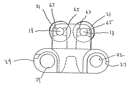
[0026]Referring to Figs. 1-12 generally and initially to
Fig. 8, the shown embodiment of the low back pressure
belt module 15 of the present invention includes a pair
of shafts 18 supported above the top surface of the

module 15. The shafts 18 support a plurality of rollers
21 to provide a low friction conveying surface. The
module 15 has a first plurality of link ends 24 and a
second plurality of link ends 27 disposed opposite from
the first link ends 24. The first plurality of link ends

24 have opposed side walls 25, 26 that provide a
transverse thickness 28 connected to an intermediate
section 48 at a first proximal portion 31 (Fig. 1). The
transverse thickness 28 extends in a direction of belt
travel 30 from the intermediate section 48 to a first

distal portion 29. The second plurality of link ends 27
have similar geometry except they extend opposite to each
other in the direction of belt travel indicated by arrow


CA 02605755 2007-10-24
WO 2006/125331 PCT/CH2006/000264
- 7 -

30. As will be evident to those of ordinary skill in the
art based on this disclosure, the belt module 15 may be.
driven in either direction along arrow 30.

[0027]The link ends 24 and 27 are offset in a direction
transverse to the direction of belt travel. Accordingly,
adjacent modules 15 can be positioned such that the link
ends 24 fit in the spaces 33 disposed between link ends
27, and link ends 27 fit in the spaces 36 disposed
between link ends 24. The link ends 24, 27 have

transverse openings 39 and 42 (Fig. 11) (which are shown
partially and in broken lines in Fig. 8) that extend
through the transverse thickness 28 between and to the
opposed side walls 25, 26. As will be evident to those
of ordinary skill in the art, modules 15 can be

positioned such that link ends 24 and 27 are intercalated
with the link ends 24 and 27 of an adjacent module 15.
The side-by-side and intercalated modules 15 can then be
connected by pivot rods 45 (Fig. 11) to provide an
endless belt capable of articulating about a sprocket to
form a conveying system.

[0028]Turning to Figs. 1-8, module 15 is formed out of
plastic or other materials suitable for many applications
including conveying of food products. The material


CA 02605755 2007-10-24
WO 2006/125331 PCT/CH2006/000264
- 8 -

should be lightweight, non-corrosive, and easily cleaned.
The module 15 is thermoformed from a plastic resin raw
material as known to those of ordinary skill in the art.
The module 15 has a base portion 47 with an intermediate

section 48 extending between first and second link ends
24, 27. Intermediate section 48 has an upper deck
surface 51 having a substantially rectangular shape in
plan view. At opposite ends of the upper surface 51 in a
direction transverse to the direction of belt travel,

shaft support members 54 and 57 extend upward from the
intermediate section 48. The shaft support members 54,
57 have openings 60 for receiving and supporting the ends
of the shafts 18. The openings 60 comprise a circular
bore formed in'the shaft support members 54, 57 and are

bounded by a curved inner wall having a diameter slightly
larger than the diameter of the shaft 18. Each opening
60 supports one of the shafts 18 and the shafts are
preferably fixed.by at least one knurled shaft end.
[0029]Intermediate shaft support members 63, 65 extend

upward from the upper surface 51 of module 15. The
intermediate shaft support members 63, 65 are disposed in
two rows along the intermediate section 48 in the
transverse direction. Turning to Fig. 6, intermediate
shaft support member 63 has an L-shaped "left-hand"


CA 02605755 2007-10-24
WO 2006/125331 PCT/CH2006/000264
- 9 -

configuration with an outer wall 66 facing the outside of
the module 15. The outer wall 66 extends from the upper
surface 51 to a top surface 69. From the top surface 69,
the member 63 extends downward along a curved shaft

support surface 72 for receiving the shaft 18. The
curved shaft support surface 72 extends to portion 74
extending to an inner wall 75 disposed toward the middle
of the intermediate section 48.

[0030]As best shown in Fig. 7, intermediate shaft support
member 65 has a "right-hand" configuration that is also
L-shaped but is a mirror image of the intermediate shaft
support member 63. Intermediate shaft support member 65
has an outer wall 78 that is substantially perpendicular
to the top surface 51 of module 15. The outer wall 78

extends upward from the surface 51 until it reaches a top
surface 81. Surface 81 extends to a curved shaft support
surface 84 that receives the shaft 18. Curved shaft
support surface 84 extends to portion 87 which in turn
extends to the top portion of an inner wall 90 disposed

toward the middle of the intermediate section 48.
[0031]Returning to Fig. 4, the mirror-imaged, L-shaped
intermediate shaft support members 63 and 65 are aligned
in the transverse direction with the openings 60 in the


CA 02605755 2007-10-24
WO 2006/125331 PCT/CH2006/000264
- 10 -

shaft support members 54 and 57 such that the shaft 18 is
supported by each of the intermediate shaft support
members 63, 65. The curved shaft support surfaces 72 and
84 align in the transverse direction such that opposite

sides of the shaft 18 are supported as best shown in Fig.
4. Because the curved openings are aligned in the
transverse direction with regard to the sides of the
shaft 18, the intermediate shaft support members 63, 65
provide excellent support for the shaft 18. The

arrangement of the intermediate support members 63, 65 in
mirrored relation provides complementary support for
opposite sides of the shaft 18. However, the staggered
arrangement of the "left-hand" and "right-hand" shaft
support members provides an open configuration with

access to the shaft for cleaning and without a narrow
slot for debris to accumulate. As an alternative, a
single intermediate shaft support member 63 may be used
in instances where the shaft support members 54, 57 are
close enough to provide sufficient additional support.

[0032]While the invention has been described in
connection with certain embodiments, it is not intended
to limit the scope of the invention to the particular
forms set forth, but, on the contrary, it is intended to
cover such alternatives, modifications, and equivalents


CA 02605755 2007-10-24
WO 2006/125331 PCT/CH2006/000264
- 11 -

as may be included within the scope of the invention as
defined by the appended claims.

Representative Drawing
A single figure which represents the drawing illustrating the invention.
Administrative Status

For a clearer understanding of the status of the application/patent presented on this page, the site Disclaimer , as well as the definitions for Patent , Administrative Status , Maintenance Fee  and Payment History  should be consulted.

Administrative Status

Title Date
Forecasted Issue Date Unavailable
(86) PCT Filing Date 2006-05-19
(87) PCT Publication Date 2006-11-30
(85) National Entry 2007-10-24
Dead Application 2012-05-22

Abandonment History

Abandonment Date Reason Reinstatement Date
2011-05-19 FAILURE TO REQUEST EXAMINATION
2011-05-19 FAILURE TO PAY APPLICATION MAINTENANCE FEE

Payment History

Fee Type Anniversary Year Due Date Amount Paid Paid Date
Application Fee $400.00 2007-10-24
Maintenance Fee - Application - New Act 2 2008-05-20 $100.00 2008-05-13
Maintenance Fee - Application - New Act 3 2009-05-19 $100.00 2009-04-28
Maintenance Fee - Application - New Act 4 2010-05-19 $100.00 2010-05-04
Owners on Record

Note: Records showing the ownership history in alphabetical order.

Current Owners on Record
HABASIT AG
Past Owners on Record
LUCCHI, MARCO
Past Owners that do not appear in the "Owners on Record" listing will appear in other documentation within the application.
Documents

To view selected files, please enter reCAPTCHA code :


To view images, click a link in the Document Description column. To download the documents, select one or more checkboxes in the first column and then click the "Download Selected in PDF format (Zip Archive)" or the "Download Selected as Single PDF" button.

List of published and non-published patent-specific documents on the CPD .

If you have any difficulty accessing content, you can call the Client Service Centre at 1-866-997-1936 or send them an e-mail at CIPO Client Service Centre.


Document
Description 
Date
(yyyy-mm-dd) 
Number of pages   Size of Image (KB) 
Abstract 2007-10-24 1 64
Claims 2007-10-24 8 215
Drawings 2007-10-24 9 119
Description 2007-10-24 11 301
Representative Drawing 2008-01-18 1 8
Cover Page 2008-01-21 1 42
Claims 2007-10-26 7 513
Description 2007-10-26 11 443
PCT 2007-10-24 3 85
Assignment 2007-10-24 3 151
Prosecution-Amendment 2007-10-24 29 934
PCT 2007-10-25 14 1,020
Fees 2008-05-13 1 36